patent · US4289118
Solar energy system with pivoting lens and collector and conduit system therefor
15 September 1981
Page 1 — bibliographic record
United
Stark
States Patent to (ii)
(54) soLAR ENERGY SYSTEM WITH PIVOTING
LENS AND COLLECTOR AND CONDUIT
SYSTEM THEREFOR . 51-2043 1/1976. Japan. (75) Inventor:
Virgil Stark, New York, N.Y. Primary Examiner-James C. Yeung . . . . . . . . Assistant Examiner-Larry Jones 73) Assignee: NE Aeria y Construction
Attorney, Agent, or Firm-Kenyon & Kenyon
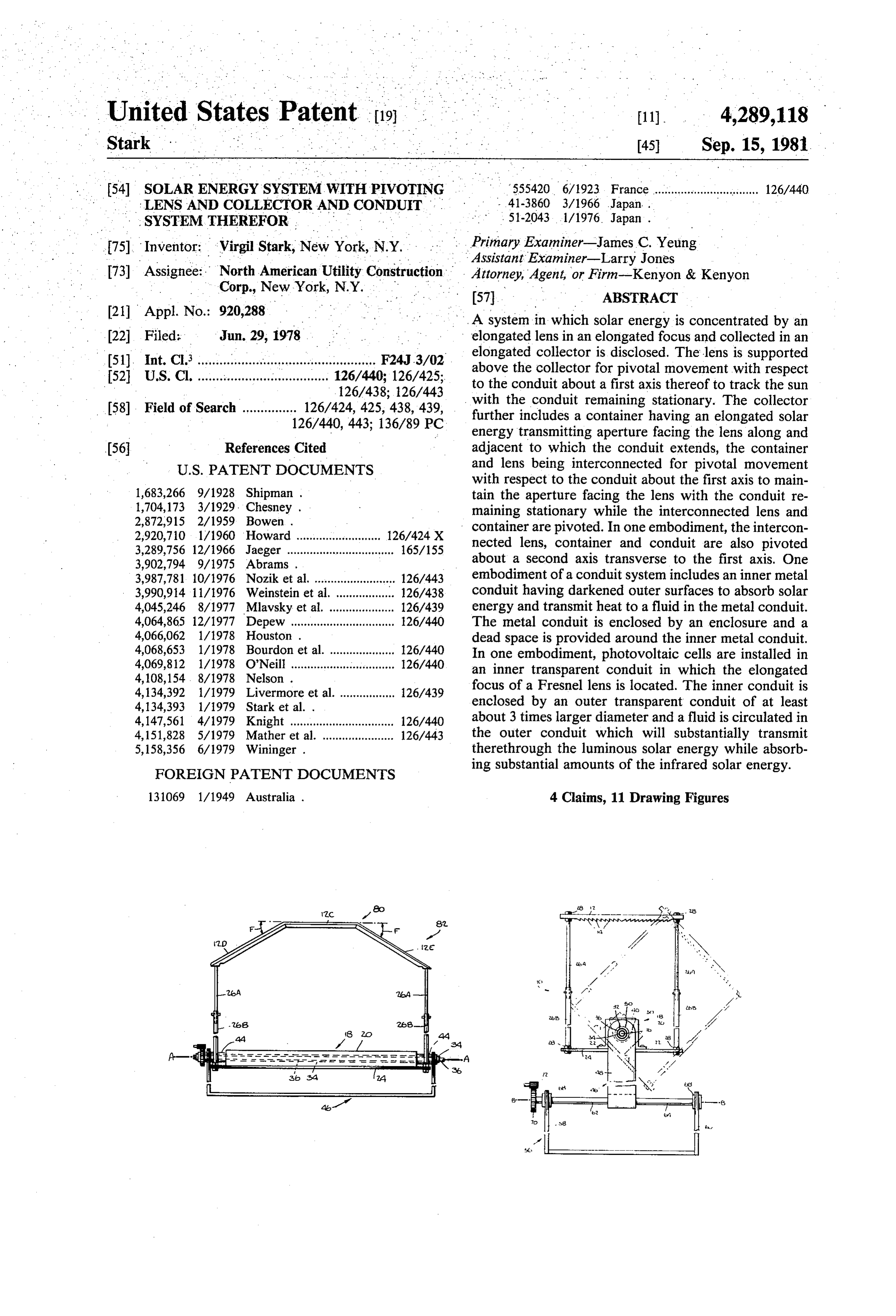
(21) Appl. No.: 920,288 A system in which solar energy is concentrated by an (22 Filed: Jun. 29, 1978 elongated lens in an elongated focus and collected in an . elongated collector is disclosed. The lens is supported s; a is a a r1367a, above the collector for pivotal movement with respect 52 U.S. Cl. ................................... 126/43 8. 26/443 to the conduit about a first axis thereof to track the sun 58, Field f Search 126/424, 425 y438,439, with the conduit remaining stationary. The collector 58). Field of Search ..............126/440 443. 136789 PC further includes a container having an elongated solar W. V, energy transmitting aperture facing the lens along and (56. References Cited adjacent to which the conduit extends, the container
with respect to the conduit about the first axis to main 1,683,266 9/1928 Shipman . tain the aperture facing the lens with the conduit re 1,704,173 3/1929. Chesney . maining stationary while the interconnected lens and 2,872,915 2/1959 Bowen. container are pivoted. In one embodiment, the intercon 2,920,710 1/1960 Howard .......................... 126/424 X nected lens, container and conduit are also pivoted 3,289,756 12/1966 Jaeger ................................. 165/155 about a second axis transverse to the first axis. One
3,987,781. 10/1976 Nozik et al. ......................... 126/443 embodiment of a conduit system includes an inner metal 3,990,914 11/1976 Weinstein et al. ... ... 126/438 conduit having darkened outer surfaces to absorb solar 4,045,246 8/1977 Mlavsky et al...... ... 126/439 energy and transmit heat to a fluid in the metal conduit. 4,064,865 12/1977 Depew ................................ 126/440 The metal conduit is enclosed by an enclosure and a 4,066,062 1/1978 Houston . dead space is provided around the inner metal conduit. 4,068,653 1/1978 Bourdon et al. .................... 126/440 In one embodiment, photovoltaic cells are installed in 4,069,812 1/1978 O'Neill ................................ 26/440 an inner transparent conduit in which the elongated 4,108,154, 8/1978 Nelson . focus of a Fresnel lens is located. The inner conduit is
4,134,393 1/1979 Stark et al. . enclosed by an outer transparent conduit of at least 4,147,561 4/1979 Knight ................................ 126/440 about 3 times larger diameter and a fluid is circulated in 4,151,828 5/1979 Mather et al. ...................... 126/443 the outer conduit which will substantially transmit 5,158,356 6/1979 Wininger . therethrough the luminous solar energy while absorb ing substantial amounts of the infrared solar energy.
FOREIGN PATENT DOCUMENTS
131069 1/1949 Australia . 4 Claims, 11 Drawing Figures
Page 2
Drawing sheet — no readable text.
Page 3
Drawing sheet — no readable text.
Page 4
Drawing sheet — no readable text.
Page 5
Drawing sheet — no readable text.
Page 6
Drawing sheet — no readable text.
Page 7
Drawing sheet — no readable text.
Page 8
Drawing sheet — no readable text.
Page 9
Drawing sheet — no readable text.
Page 10
and a fluid which absorbs substantial amounts of infra soLARENERGY SYSTEM WITH PIVOTINGLENs red solar energy circulated in the outer conduit. AND COLLECTOR AND CONDUITSYSTEM More particularly according to a first aspect of the THEREFOR invention, the solar energy is concentrated by elongated lens means in an elongated focus and collected in an
BACKGROUND OF THE INVENTION elongated collector which includes at least one elon The present invention relates to methods and appara gated conduit, the elongated focus being located sub tus for concentrating and collecting solar energy and stantially in or on the surface of and substantially along more particularly to methods and apparatus utilizing the at least one conduit and at least the lens means being elongated lenses and elongated conduits in which parts O supported above that at least one conduit for pivotal of the system are movable to track the sun. The inven duit about thereof movement with respect to the at least one con the first axis to track the sun. Further in tion also relates to conduit systems for collecting and accordance with this aspect of the invention, the elon converting solar energy to heat and to electricity.
Co-pending Application Ser. No. 746,065 filed on 15 an gated collector includes an elongaged container having Nov. 30, 1976 on which U.S. Pat. No. 4,134,393 issued elongated solar energy aperture therein which faces on Jan. 16, 1979, of which I am the sole assignee, dis one lens the means, along and adjacent to which the at least conduit extends, the lens means and container being closes elongated lenses for concentrating solar energy interconnected in an elongated focus and an elongated collector which the at least one for pivotal movement with respect to conduit about the first axis to maintain includes at least two conduits therein with the elon 20 the aperture facing the lens means while the at least one gated focus being located substantially in or on and conduit remains stationary. In accordance with another substantially along the length of one of the conduits. aspect of the invention, the interconnected lens means, However, while it is appreciated that tracking the sun will increase collection, U.S. Pat. No. 4,134,393 merely container and at least one conduit are pivotable about another axis transverse to the first axis.
teaches pivoting the lens to track the sun. See for exam 25 In accordance with the first aspect of the invention, ples FIGS. 11, 18-22, and 25-27 of U.S. Pat. No. first support means are provided for supporting the lens
U.S. Pat. No. 4,134,393 also discloses a collector gated means above the at least one conduit to locate the elon having a plurality of conduits each of which contains a substantiallyfocus of the lens means substantially in or on and - fluid therein which is circulated therethrough. There is, 30 otal movement along the at least one conduit and for piv however, no disclosure of an enclosure for an inner the at least oneofconduit at least the lens means with respect to about the first axis with the at conduit having a darkened outer surface which absorbs least one conduit remaining stationary. The first support the solar energy focused thereon. means includes connecting means interconnecting the SUMMARY OF THE INVENTION lens means and the container for pivotal movement of 35 the interconnected lens means and container with re
It is an object of the present invention to increase spect to the at least one conduit about the first axis. solar energy collection in a system which includes elon gated lens means and an elongated collector by tracking ingAccording to a preferred embodiment, the connect means includes a plate member to which the con the sun.
tainer is connected and a plurality of rods interconnect
It is also an object of the present invention to provide ing such a tracking solar energy system in which an elon the moments the lens means and the plate member. Preferably, above and below the first axis are substan gated conduit of the collector remains stationary during tially equal to substantially balance the interconnected movement of the other parts of the system. lens, plate and container about the first axis. This is It is another object of the present invention to pro preferably accomplished by selection of the weight of vide a conduit system for collecting solar energy which 45 the system components and of the distances by which is capable of carrying fluids at high temperatures with they are displaced from the first axis. The container reduced heat losses. includes hollow necked portions at the ends thereof It is still another object of the present invention to having the same axis as the first axis, and through which provide the aforementioned conduit system in which the at least one conduit extends, the first support means metal piping enclosed by glass tubing form conduits of 50 including first pivot means pivotally connecting the first the system, the metal piping having a darkened outer support means to the necked portions. This permits the surface which absorbs the solar energy. at least one conduit to remain stationary while the inter It is yet another object of the present invention to connected container and lens means are pivoted about provide a collector having photovoltaic cells therein for the first axis.
conversion of solar energy to electricity in which the 55 In accordance with an aspect of the invention, the efficiency of the cells is not substantially reduced by apparatus is disposed so the first axis extends generally heat otherwise produced by infrared solar energy. in the north-south direction, so that the interconnected Briefly, these and other objects of the present inven lens means and container may be pivoted about the first tion are achieved: by concentrating the solar energy in axis to track the sun on a daily basis, the conduit remain an elongated focus located substantially in or on the 60 ing stationary as the container is pivoted. surface of and substantially along at least one conduit The apparatus in accordance with another aspect of and at least pivoting the lens means about a first axis of the invention further comprises second support means the at least one conduit; by a conduit system in which an for supporting the interconnected container and lens inner conduit is enclosed by an enclosure with the en means for pivotal movement about an axis transverse to closed inner conduit and enclosure being enclosed by an 65 the first axis, the first support means including an elon outer conduit; and by a collector having inner and outer gated member supporting and connecting the first pivot conduits which are transparent at least in part with means, and the second support means including second photovoltaic cells being disposed in the inner conduit pivot means pivotally connecting the elongated mem
Page 11
ber to the first support means so that the interconnected conduit which absorbs the solar energy and transmits container and lens means are pivotal about the trans heat to the fluid therein. In the preferred embodiment, verse axis. In accordance with this aspect of the inven the inner conduit comprises metal piping and the enclo tion, the apparatus is disposed so that the first axis ex sure and outer conduit comprise glass tubing. The inner tends generally in the east-west direction, so that the and outer conduits carry heat exchange fluids while the interconnected container and lens may be pivoted by dead space around the inner conduit provides insulation the first support means to track the sun on a daily basis for the fluid therein.
and by the second support means to track the sun on a According to an aspect of the invention, photovoltaic seasonal basis. cells which produce electricity from luminous solar According to the disclosure, the lens means com 10 energy of about 0.4 to about 0.7 microns wavelength are prises at least one Fresnel lens having prisms extending installed in an inner conduit which is transparent at least substantially parallel to the first axis. in part of an elongated collector. The elongated focus of In one disclosed embodiment of the invention, the a Fresnel lens is located on the cells in the inner conduit. apparatus comprises a plurality of adjacently disposed The inner conduit is enclosed by an outer conduit collectors and a plurality of adjacently disposed lens 15 means, a first lens means being disposed above a first which is transparent at least in part and of at least about 3 and preferably more than about 5 times larger diame collector and a second lens means being disposed above ter than the inner conduit, and a fluid is circulated in the a second collector, the collectors being aligned so that outer conduit which will substantially transmit there the at least one conduit extends through the collectors, through and the two lens means and collectors being intercon 20 substantialtheamounts luminous solar energy while absorbing of the infrared solar energy. Due to nected and supported by the first support means for the large difference in diameters of the conduits and the pivotal movement about the first axis, the elongated focus of at least one of the lens means being located on characteristics of the fluid, most of the infrared solar energy will be absorbed by the fluid. This arrangement a substantial portion of the at least conduit in at least one increases of the collectors regardless of season. According to this 25 taic cells the production of electricity by the photovol since their efficiency is not substantially re embodiment, the lens means and collectors are pivoted duced by the heat that would be generated by infrared about the first axis only on a daily basis with the at least solar energy otherwise reaching the cells. In the pre one conduit remaining stationary regardless of season.
In another disclosed embodiment of the invention, ferred embodiment, the fluid is water. the lens means comprise at least three Fresnel lenses 30 BRIEF DESCRIPTION OF THE DRAWINGS having prisms extending substantially parallel to the first axis, a central Fresnel lens having prisms extending The present invention is illustrated by way of exam substantially parallel to the first axis, a second Fresnel ple and not limitation in the figures of the accompany lens adjacent to one end of the central Fresnel lens and ing drawings in which like references indicate similar having prisms extending in the same direction as the 35 parts and in which:
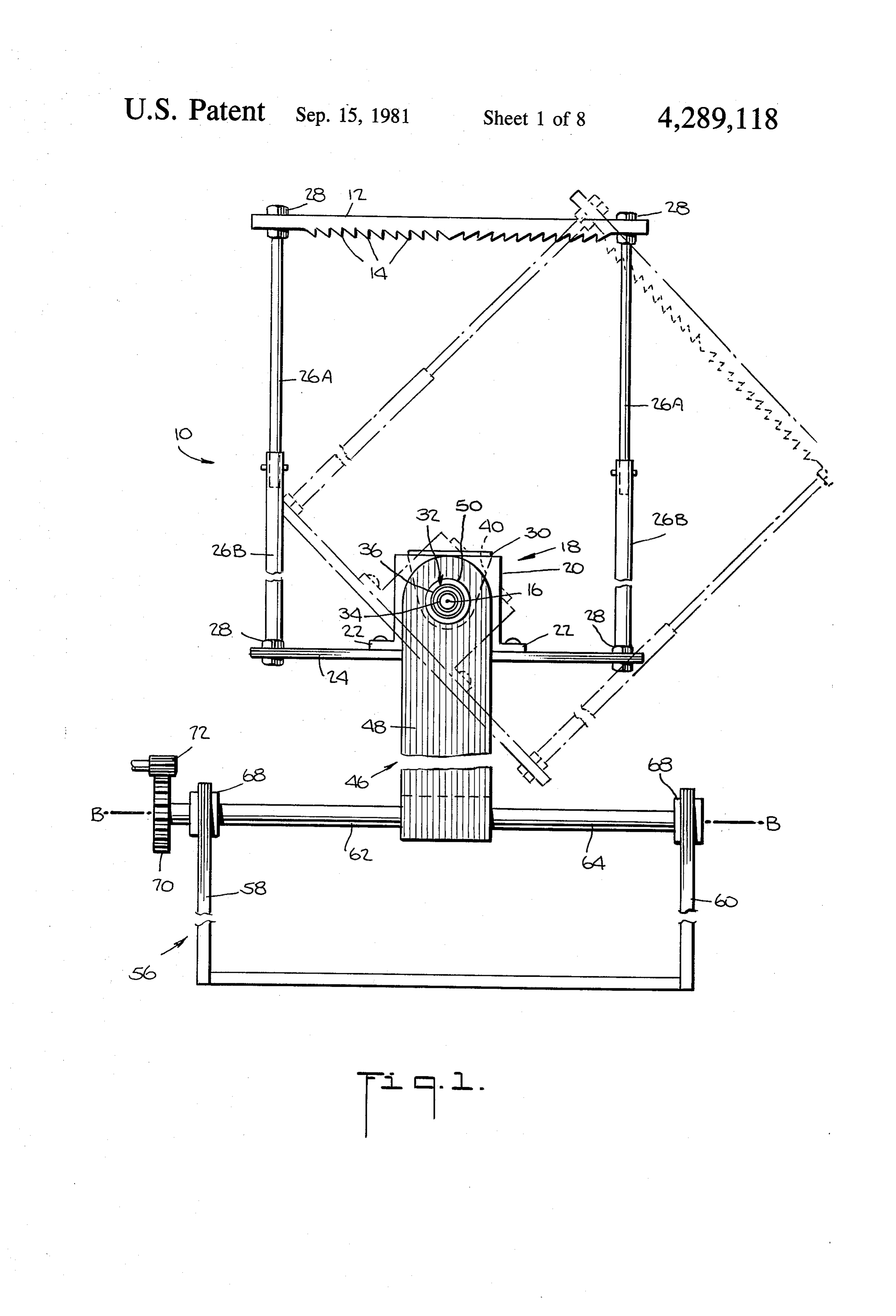
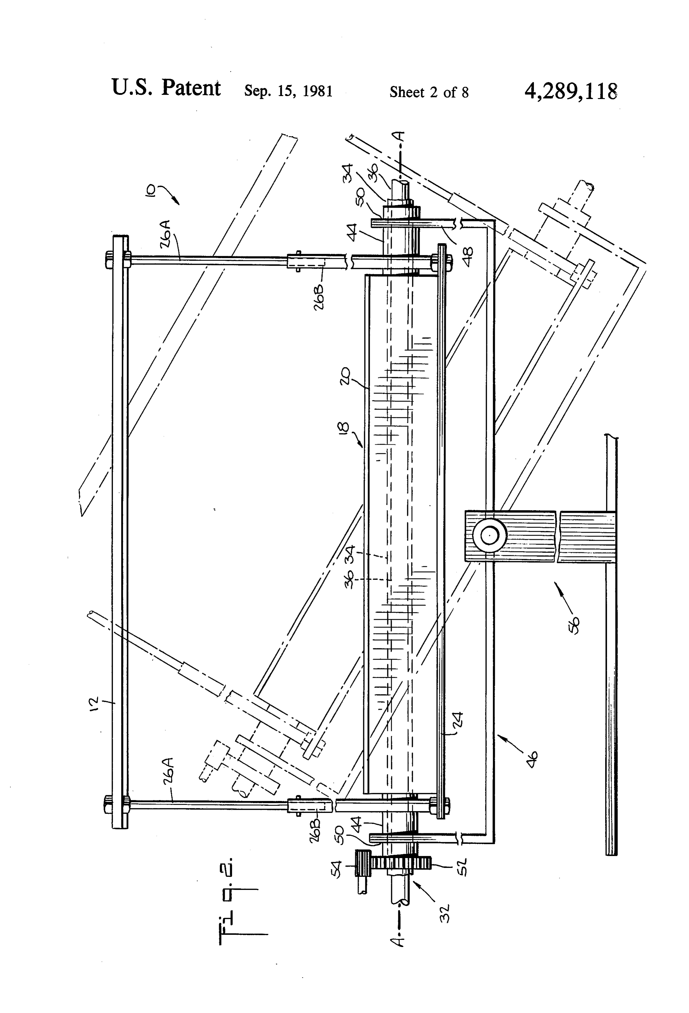
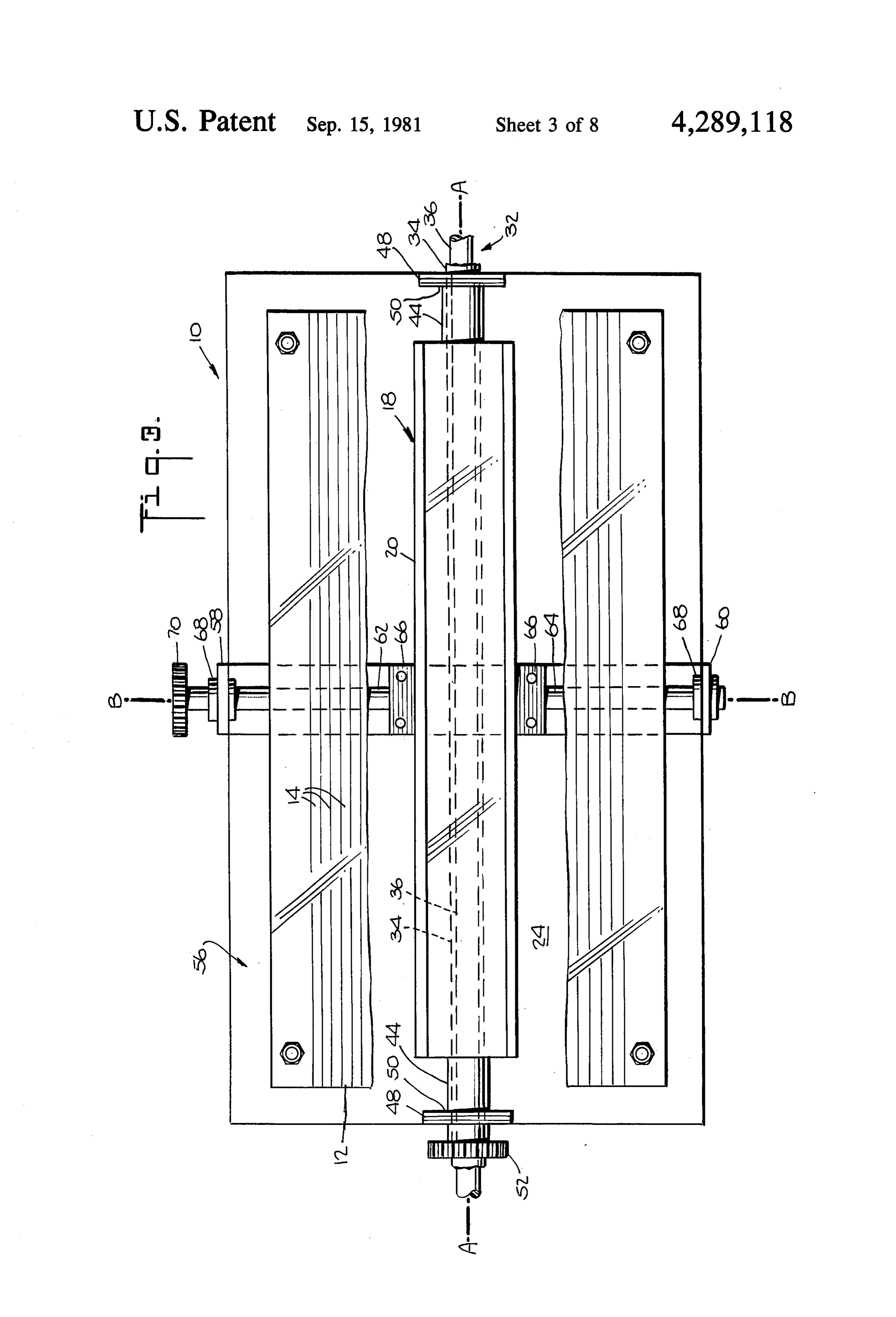
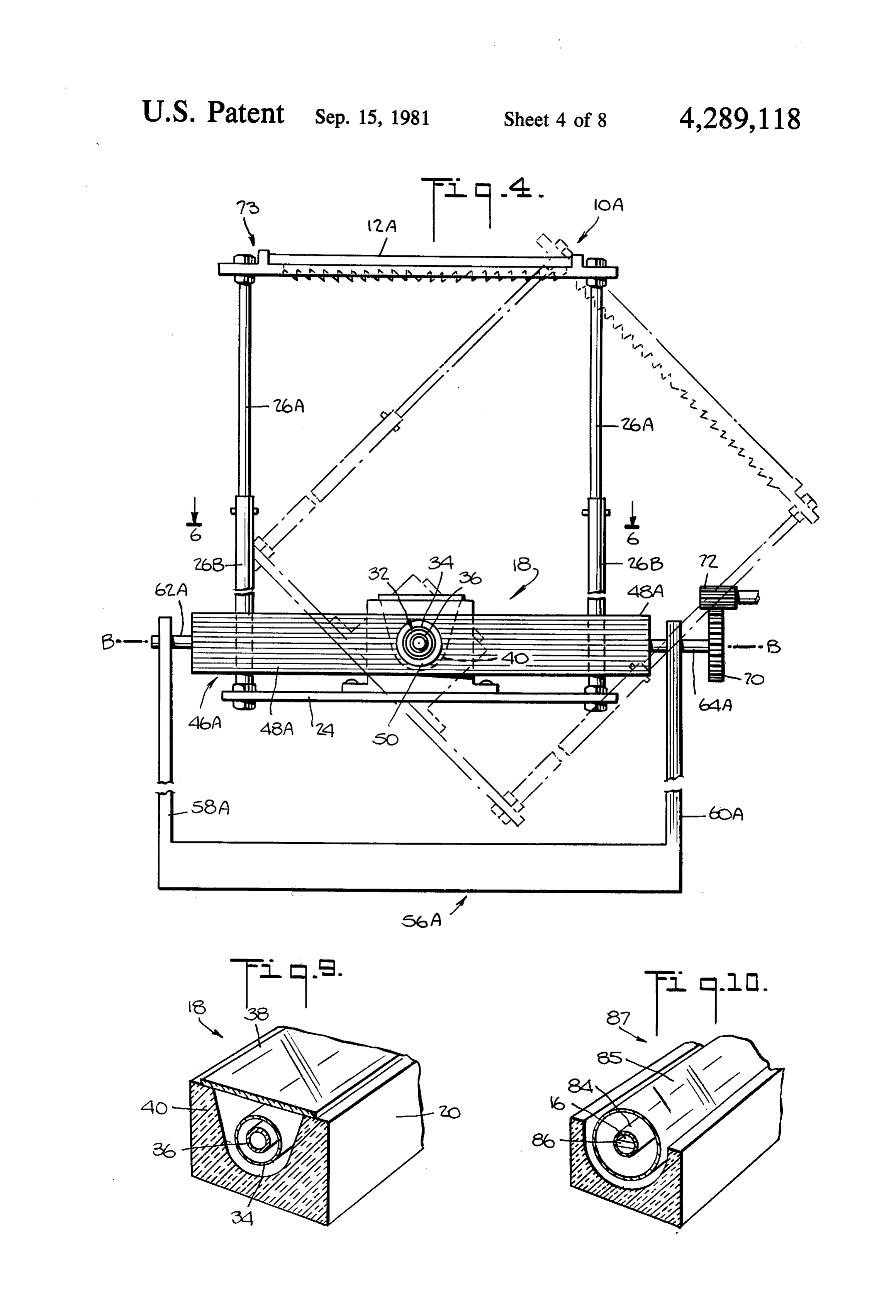
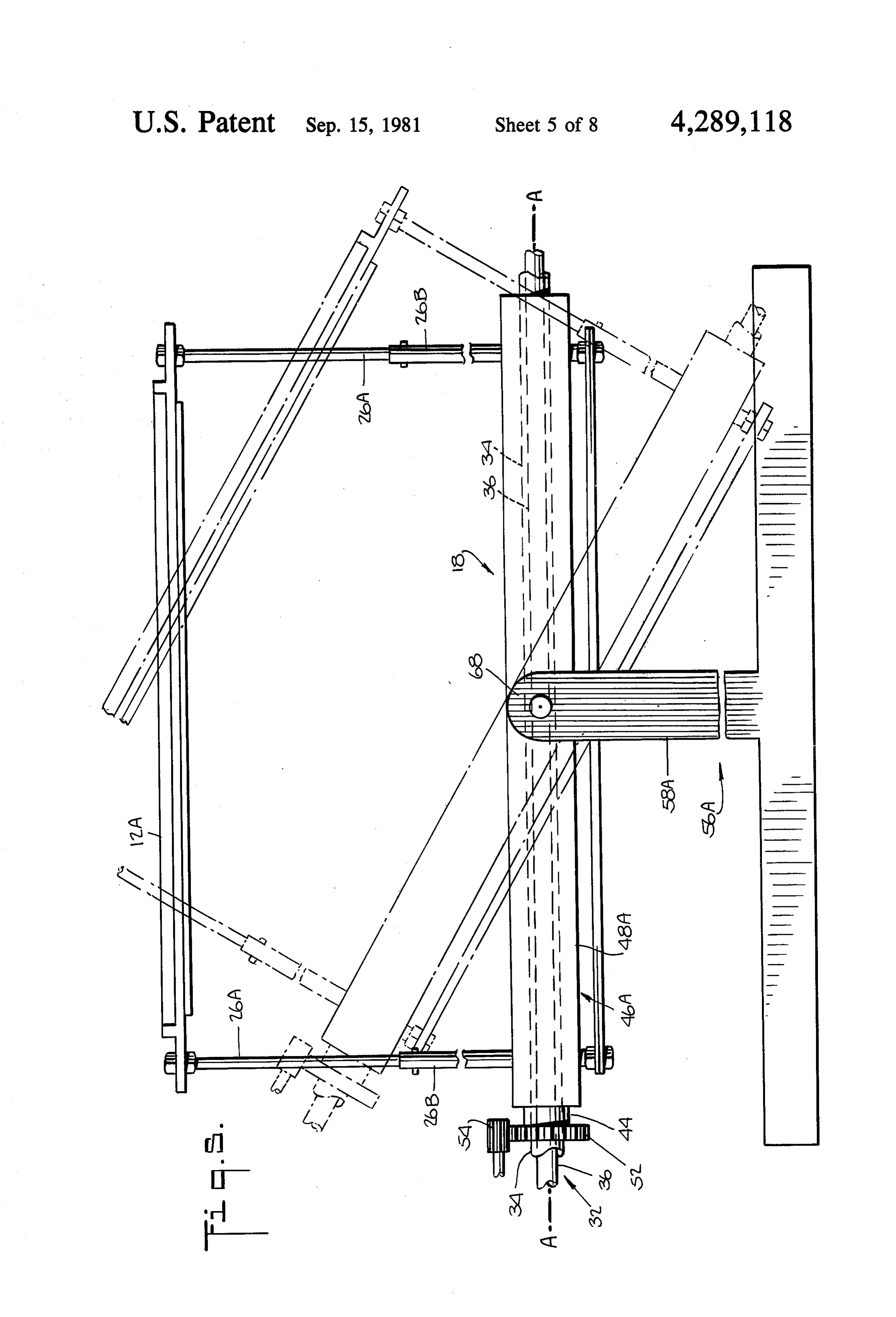
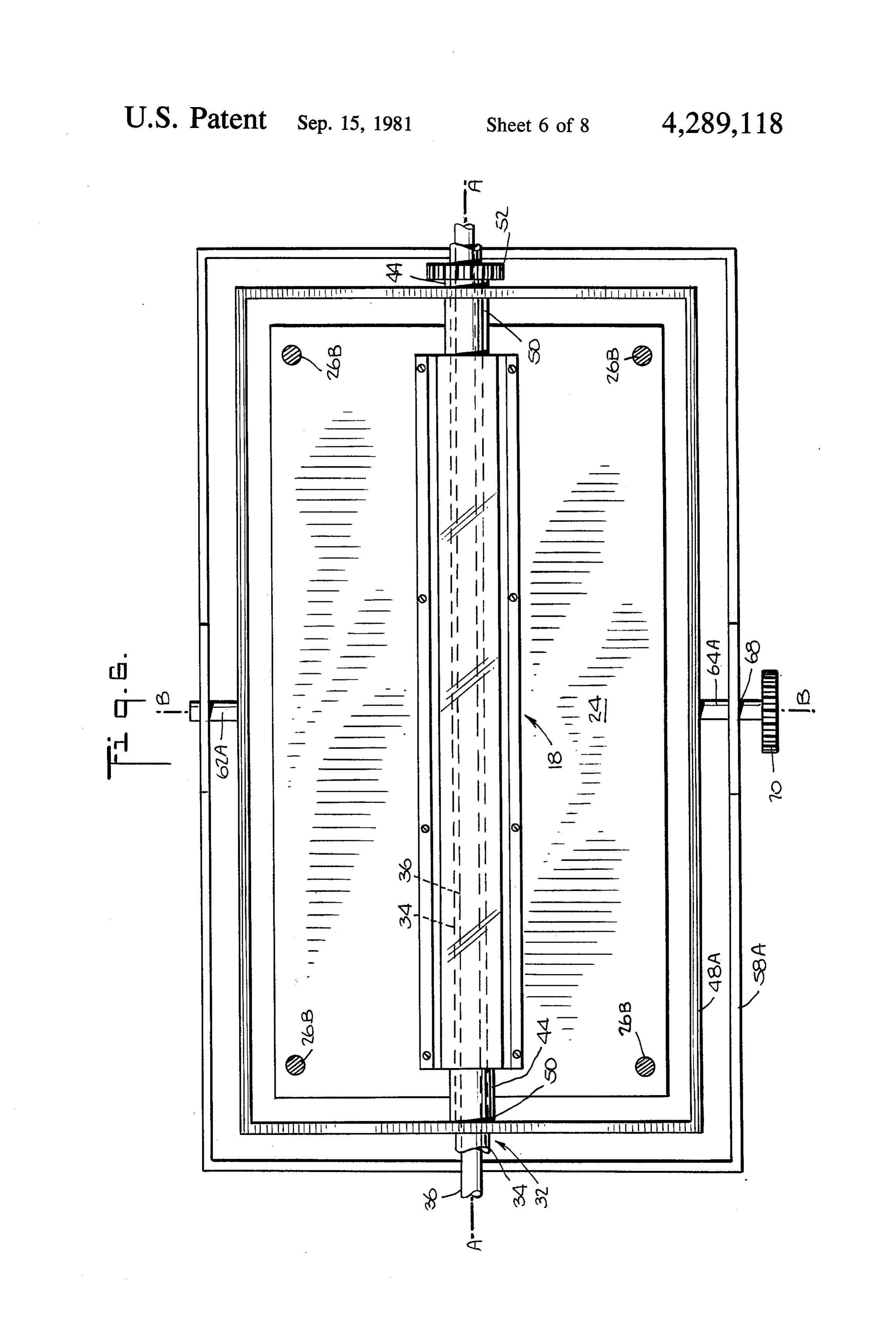
FIG. 1 is an end, elevation schematic view of solar prisms of the central lens and inclined downwardly at energy apparatus and support apparatus according to an angle thereto towards the collector, and a third Fres nel lens adjacent to the other end of the central Fresnel the invention, the solar energy apparatus including an lens and having prisms extending in the same direction elongated Fresnel lens and an elongated collector as the prisms of the central lens and inclined down which comprises an elongated container having at least wardly at an angle thereto towards the collector and one elongated conduit therein, the collector container opposed to the second Fresnel lens, so that the elon and lens being interconnected and supported by the gated focus of at least one of the lenses is located on a support apparatus to permit the lens and container to be substantial portion of the at least one conduit regardless pivoted free of the conduit about a longitudinal axis of season. According to this embodiment also, the lenses 45 extending through the conduit, and also permitting and collector are pivoted about the first axis on a daily pivoting of the interconnected lens and container about . basis with the at least one conduit remaining stationary another axis transverse to the longitudinal axis; regardless of season. FIG. 2 is a side elevation schematic view of the solar In accordance with still another aspect of the inven energy apparatus and support apparatus shown in FIG. tion, an elongated conduit system for collecting solar 50 1;
energy in an elongated focus is provided in which the FIG. 3 is a top plan schematic view of the solar en elongated focus is located substantially in or on and ergy apparatus and support apparatus of FIG. 1; substantially along the conduit system, which comprises FIGS. 4, 5 and 6 are respectively end elevation, side two elongated conduits for passing fluids therethrough elevation and top plan schematic views similar to those and an enclosure for a first of the conduits, the conduits 55 of FIGS. 1, 2 and 3, respectively, of solar energy appa and enclosure being disposed so that an inner of the ratus and support apparatus according to another em conduits containing a fluid therein is enclosed by the bodiment of the invention, FIG. 6 being taken along enclosure, there being a dead space in the enclosure lines 6-6 of FIG. 4.;
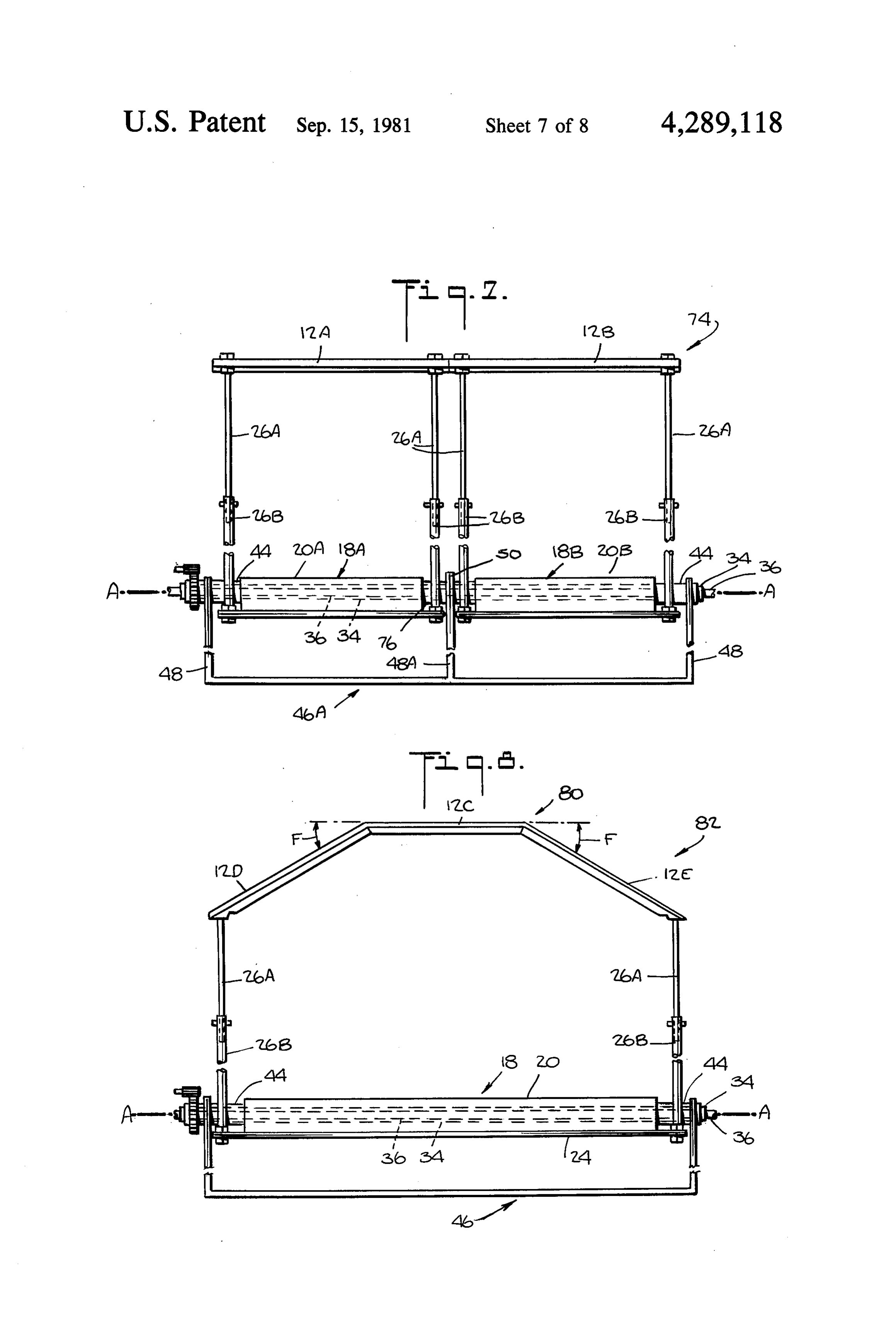
surrounding the inner conduit, and an outer of the con FIG. 7 is a side elevation schematic view of solar duits containing a fluid therein encloses the enclosure energy apparatus and of support apparatus according to and inner conduit, at least part of the enclosure and the invention comprising two elongated Fresnel lenses outer conduit being transparent with transparent por arranged in series and two elongated collectors ar tions thereof being aligned and adapted to transmit the ranged in series, each collector including a collector solar energy in the elongated focus therethrough. The container and at least one conduit therein with the con inner conduit is opaque with a darkened outer surface 65 duits of the containers being connected, the lenses and and the dead space in the enclosure preferably contains collector containers being interconnected and sup air, the elongated focus being located substantially on ported by the support apparatus to permit the intercon and substantially along the outer surface of the inner nected lenses and containers to be pivoted free of the
Page 12
conduits about a longitudinal axis extending through the such as system shown in FIG. 11 and described herein conduits; after may be utilized. The Fresnel lens and collector FIG. 8 is an end elevation schematic view of solar container are interconnected and the conduit system energy apparatus and support apparatus according to disposed so that the elongated focus 16 is located sub the invention including three Fresnel lenses arranged in stantially in or on and substantially along conduit 34 or series, with the Fresnel lenses adjacent to the central conduit 36. The advantages of the elongated collector Fresnel lens being disposed at an angle thereto, and an system and elongated lens in which the elongated focus elongated collector similar to that of FIG. 1, the Fresnel is located in or on the conduits of the collector system lenses and collector container being interconnected and supported by support apparatus to permit the intercon 10 and the operation thereof are described in the aforemen tioned patent.
nected lenses and container to be pivoted free of the The ends of the collector container 20 have tubular conduit about a longitudinal axis extending through the necked portions 44 rigidly connected thereto by bolts, conduit; for example. The tubular-necked portions 44 are hollow FIG. 9 is a cross-section perspective of a collector and the conduits 34 and 36 extend therethrough. The utilizable in the apparatus of FIGS. 1-8; 15 conduits are supported freely of the collector container
FIG. 10 is a cross-section perspective view of a col by support means which are not shown. As will now be lector which includes photovoltaic cells according to described, the interconnected collector container and the invention; and Fresnel lens are pivotably supported about an elongated FIG. 11 is a cross-sectional schematic view of a con duit system according to the invention which includes 20 axis A-A extending through the center of the inner conduit 34. Thus, the lens and collector container may an innermost metal conduit enclosed within intermedi ate and outer transparent conduits, the conduit system be A-A.
rotated independently of the conduits about the axis being utilizable in any of the collectors of FIGS. 1-8. A support 46 extends below the plate 24 and has DESCRIPTION OF THE PREFERRED 25 vertically extending arms 48 which rotatably support EMBODEMENTS the interconnected container and lens. Bearings 50 are Referring more particularly to the drawings, solar disposed in arms 48 and rotatably support the tubular energy and support apparatus according to the inven portions 44 connected to the container so that the con tion are illustrated. In FIGS. 1-3 solar energy system 10 tainer is rotatable about axis A-A. A gear 52 is rigidly includes an elongated Fresnel lens 12 having longitudi 30 connected to one tubular portion 44 so that rotation of nal prisms 14 which cause the solar energy to be con the gear causes the interconnected container and lens to centrated in an elongated linear focus 16. Disposed pivot. Drive gear 54 drives gear 52 to cause rotation of below the Fresnel lens 12 at the focus 16 thereof is an theThe system.
interconnected lens and container are further elongated collector 18 which includes an insulated con tainer 20. The bottom of the container 20 is flanged and 35 supported by support 56 so that they may be pivoted the flanges 22 are bolted to an elongated plate 24 which about an axis B-B which is perpendicular to axis is approximately the same size as the Fresnel lens 12. A-A. Support 56 extends below support 46 and in Telescoping interconnected rods 26A, 26B having cludes vertically extending arms 58, 60 through which threaded ends 28 are used to interconnect the Fresnel one end of shafts 62, 64 rotatably extend with the other lens and plate. The rods are telescoped in order to ad end rigidly connected to the central portion of support just the distance between the Fresnel lens and the con 46 by bolted plates 66, for example. The shafts 62, 64 are tainer. rotatably supported in the arms 58, 60 by bearings 68 so The collector may be of the type described in U.S. that the shafts are freely rotatable in the arms and sup Pat. No. 4,134,393, which is hereby incorporated by ported thereby, rotation of the shafts causing pivoting reference, and of which I am the sole assignee. Such a 45 of the support 46 about axis B-B. A gear 70 is rigidly collector is shown in FIG. 9. Disposed in the collector secured to the free end of shaft 62 such that rotation of container 20 is a conduit system 32 which includes con the gear causes the shaft to rotate and pivot the support duits 34 and 36. Conduit 34 is disposed within and en 46 and the interconnected lens and container about axis closed by conduit 36. The outer conduit 36 is wholly B-B. A drive gear 72 drives the gear 70. transparent or a portion of the outer conduit is transpar 50 The lens and interconnected collector container are ent in order to allow solar energy to pass therethrough, thus supported by a gimbel system comprised of sup The inner conduit 34 may be wholly or partially trans ports 46 and 56.
parent in order to allow solar energy to pass there The system shown in FIGS. 1-3 is arranged so that through or the inner conduit may be at least partially the elongated axis A-A of the conduits extends in the is opaque and darkened at its bottom in order to absorb 55 north-south direction. As so arranged, the system is solar energy passing through the transparent part, or caused to rotate about axis A-A on a daily basis to I. opaque at least along the top outer surface to absorb follow and track the daily position of the sun. The inter solar energy therealong. A heat'exchange fluid is circur. connected lens and collector are rotatable to angles up lated through each of the conduits and the fluids are to about 100', for example, in each direction from the ... preferably different but the same type fluid may be 60 horizontal about axis A-A. The interconnected lens circulated in each of the conduits. Preferably, liquids and collector are also rotatable about axis B-B but on are circulated in the conduits. The collector container is a seasonal basis to follow the seasonal position of the insulated, as mentioned, and is closed by a transparent sun. The interconnected lens and container are rotatable plate 38 which provides a greenhouse heating effect in up to angles up to about 23.5' over a 90 day period in the trough 40 in which the conduit system is disposed. each direction about axis B-B. For example, the sys The conduit system, 32 is of the type described in the tem will be rotated from the horizontal position to an aforementioned patent. However, the invention is not angle of about up to 25.5' over the time span of a season, limited to such conduit systems and a conduit system. i.e. over a 90 day period. The precise angles to which
Page 13
the system is rotated will depend upon the latitude of The systems shown in FIGS. 1-6 may also be ar the location of the system and the time of year. ranged so that the elongated axis A-A extends gener Use of Fresnel lens as the concentrating element, ally in the east-west direction. When the systems 10, which is of relatively low weight, reduces the weight 10A are so arranged, the interconnected lens and collec disposed above axis A-A and permits a system weight tor container are merely supported by supports 46, 46A distribution such that the system is not "top heavy" and for rotation about the single axis A-A, i.e., supports 56, will not be unstable in the rotated positions. The prod 56A are not utilized. The supports 46, 46A are used to uct of the weight of the plate 24 and container portions permit rotation of the interconnected lens and collector and their distance from axis A-A, i.e. the moment container on a daily basis, with rotation occurring as effectively of plate 24 about axis A-A, is chosen to 10 described above over angles of up to about 110 in each equal the product of the weight of the Fresnel lens, its direction with the horizontal. When the interconnected frame and supports and the distances thereof from axis lens and container are supported by only supports 46, A-A, i.e. the effective moment of the Fresnel lens. 46A for rotation about only axis A-A, then the inde This balances the effective weight above and below the pendently supported conduits may be rigidly supported axis A-A. For instance To maintain the system in the 15 at the ends thereof since the conduits will remain sta rotated positions, the drive gears 54, 72 are locked in tionary throughout the year.
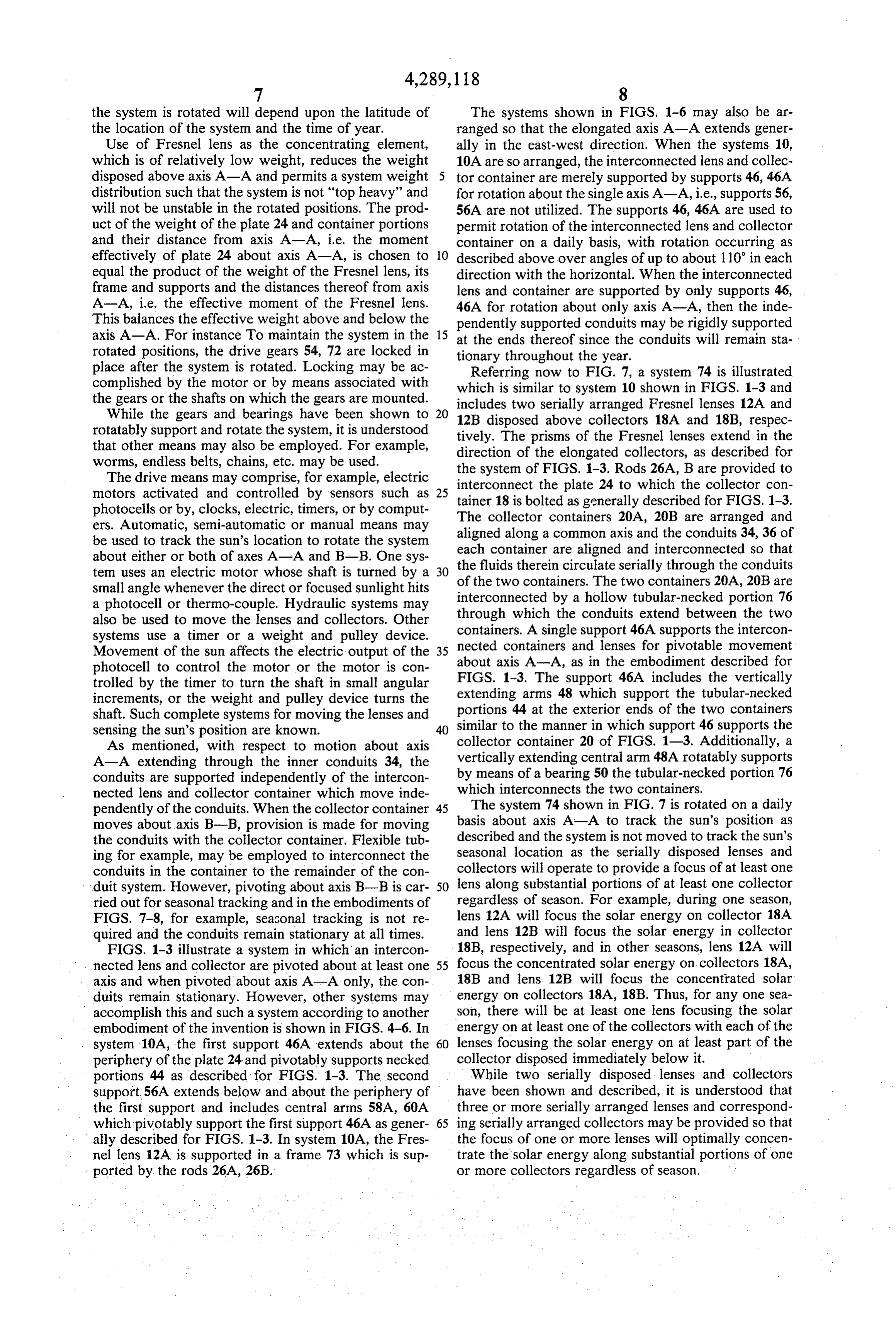
place after the system is rotated. Locking may be ac Referring now to FIG. 7, a system 74 is illustrated complished by the motor or by means associated with which is similar to system 10 shown in FIGS. 1-3 and the gears or the shafts on which the gears are mounted. includes two serially arranged Fresnel lenses 12A and While the gears and bearings have been shown to 20 12B disposed above collectors 18A and 18B, respec rotatably support and rotate the system, it is understood tively. The prisms of the Fresnel lenses extend in the that other means may also be employed. For example, direction of the elongated collectors, as described for worms, endless belts, chains, etc. may be used.
The drive means may comprise, for example, electric interconnectofthe the system FIGS. 1-3. Rods 26A, B are provided to motors activated and controlled by sensors such as 25 tainer 18 is boltedplate 24 to which the collector con as generally described for FIGS. 1-3.
photocells or by, clocks, electric, timers, or by comput The collector containers 20A, 20B are arranged and ers. Automatic, semi-automatic or manual means may aligned along a common axis and the conduits 34, 36 of be used to track the sun's location to rotate the system each container about either or both of axes A-A and B-B. One sys the fluids thereinarecirculate aligned and interconnected so that ten uses an electric motor whose shaft is turned by a 30 of the two containers. The serially through the conduits small angle whenever the direct or focused sunlight hits interconnected by a hollow tubular-necked20A, two containers 20B are portion 76 a photocell or thermo-couple. Hydraulic systems may also be used to move the lenses and collectors. Other through which the conduits extend between the two systems use a timer or a weight and pulley device. containers. A single support 46A supports the intercon nected containers and lenses for pivotable movement
Movement of the sun affects the electric output of the 35 about photocell to control the motor or the motor is con FIGS. axis A-A, as in the embodiment described for trolled by the timer to turn the shaft in small angular 1-3. The support 46A includes the vertically increments, or the weight and pulley device turns the extending arms 48 which support the tubular-necked shaft. Such complete systems for moving the lenses and portions 44 at the exterior ends of the two containers sensing the sun's position are known. 40 similar to the manner in which support 46 supports the collector container 20 of FIGS. 1-3. Additionally, a
As mentioned, with respect to motion about axis vertically
A-A extending through the inner conduits 34, the extending central arm 48A rotatably supports conduits are supported independently of the intercon by means of a bearing 50 the tubular-necked portion 76 which interconnects the two containers.
nected lens and collector container which move inde pendently of the conduits. When the collector container 45 The system 74 shown in FIG. 7 is rotated on a daily moves about axis B-B, provision is made for moving basis about axis A-A to track the Sun's position as the conduits with the collector container. Flexible tub described and the system is not moved to track the sun's ing for example, may be employed to interconnect the seasonal location as the serially disposed lenses and conduits in the container to the remainder of the con collectors will operate to provide a focus of at least one duit system. However, pivoting about axis B-B is car- 50 lens along substantial portions of at least one collector ried out for seasonal tracking and in the embodiments of regardless of season. For example, during one season, FIGS. 7-8, for example, seasonal tracking is not re lens 12A will focus the solar energy on collector 18A quired and the conduits remain stationary at all times. and lens 12B will focus the solar energy in collector FIGS. 1-3 illustrate a system in which an intercon 18B, respectively, and in other seasons, lens 12A will nected lens and collector are pivoted about at least one 55 focus the concentrated solar energy on collectors 18A, axis and when pivoted about axis A-A only, the con 18B and lens 12B will focus the concentrated solar duits remain stationary. However, other systems may energy on collectors 18A, 18B. Thus, for any one sea accomplish this and such a system according to another son, there will be at least one lens focusing the solar embodiment of the invention is shown in FIGS. 4-6. In energy on at least one of the collectors with each of the system 10A, the first support 46A extends about the 60 lenses focusing the solar energy on at least part of the periphery of the plate 24 and pivotably supports necked collector disposed immediately below it. portions 44 as described for FIGS. 1-3. The second While two serially disposed lenses and collectors support 56A extends below and about the periphery of have been shown and described, it is understood that the first support, and includes central arms 58A, 60A three or more serially arranged lenses and correspond which pivotably support the first support 46A as gener- 65 ing serially arranged collectors may be provided so that ally described for FIGS. 1-3. In system 10A, the Fres the focus of one or more lenses will optimally concen nel lens 12A is supported in a frame 73 which is sup trate the solar energy along substantial portions of one ported by the rods 26A, 26B. or more collectors regardless of season.
Page 14
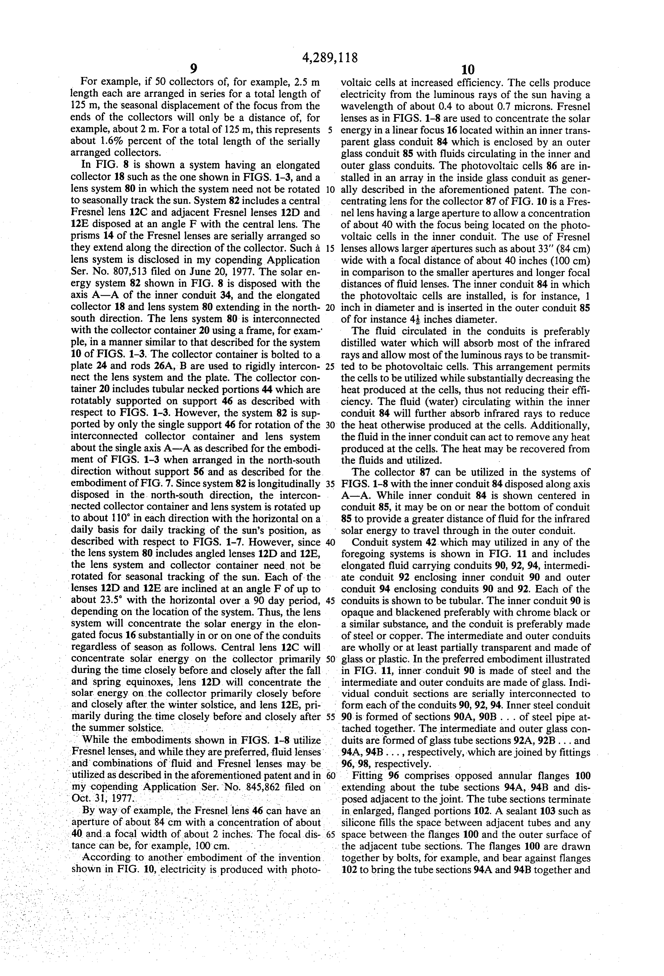
For example, if 50 collectors of, for example, 2.5 m voltaic cells at increased efficiency. The cells produce length each are arranged in series for a total length of electricity from the luminous rays of the sun having a 125 m, the seasonal displacement of the focus from the wavelength of about 0.4 to about 0.7 microns. Fresnel ends of the collectors will only be a distance of, for lenses as in FIGS. 1-8 are used to concentrate the solar example, about 2 m. For a total of 125 m, this represents energy in a linear focus 16 located within an inner trans about 1.6% percent of the total length of the serially parent glass conduit 84 which is enclosed by an outer arranged collectors. glass conduit 85 with fluids circulating in the inner and In FIG. 8 is shown a system having an elongated outer glass conduits. The photovoltaic cells 86 are in collector 18 such as the one shown in FIGS. 1-3, and a stalled in an array in the inside glass conduit as gener lens system 80 in which the system need not be rotated 10 ally described in the aforementioned patent. The con to seasonally track the sun. System 82 includes a central centrating lens for the collector 87 of FIG. 10 is a Fres Fresnel lens 12C and adjacent Fresnel lenses 12D and nel lens having a large aperture to allow a concentration 12E disposed at an angle F with the central lens. The of about 40 with the focus being located on the photo prisms 14 of the Fresnel lenses are serially arranged so voltaic cells in the inner conduit. The use of Fresnel they extend along the direction of the collector. Such a 15 lenses allows larger apertures such as about 33" (84 cm) lens system is disclosed in my copending Application wide with a focal distance of about 40 inches (100 cm) Ser. No. 807,513 filed on June 20, 1977. The solar en in comparison to the smaller apertures and longer focal ergy system 82 shown in FIG. 8 is disposed with the distances of fluid lenses. The inner conduit 84 in which axis A-A of the inner conduit 34, and the elongated the photovoltaic cells are installed, is for instance, 1 collector 18 and lens system 80 extending in the north 20 inch in diameter and is inserted in the outer conduit 85 south direction. The lens system 80 is interconnected of for instance 4 inches diameter.
with the collector container 20 using a frame, for exam The fluid circulated in the conduits is preferably ple, in a manner similar to that described for the system distilled water which will absorb most of the infrared 10 of FIGS. 1-3. The collector container is bolted to a rays and allow most of the luminous rays to be transmit plate 24 and rods 26A, B are used to rigidly intercon 25 ted to be photovoltaic cells. This arrangement permits nect the lens system and the plate. The collector con the cells to be utilized while substantially decreasing the tainer 20 includes tubular necked portions 44 which are heat produced at the cells, thus not reducing their effi rotatably supported on support 46 as described with ciency. The fluid (water) circulating within the inner respect to FIGS. 1-3. However, the system 82 is sup conduit 84 will further absorb infrared rays to reduce ported by only the single support 46 for rotation of the 30 the heat otherwise produced at the cells. Additionally, interconnected collector container and lens system the fluid in the inner conduit can act to remove any heat about the single axis A-A as described for the embodi produced at the cells. The heat may be recovered from ment of FIGS. 1-3 when arranged in the north-south the fluids and utilized.
direction without support 56 and as described for the The collector 87 can be utilized in the systems of embodiment of FIG. 7. Since system 82 is longitudinally 35 FIGS. 1-8 with the inner conduit 84 disposed along axis disposed in the north-south direction, the intercon A-A. While inner conduit 84 is shown centered in nected collector container and lens system is rotated up conduit 85, it may be on or near the bottom of conduit to about 110 in each direction with the horizontal on a 85 to provide a greater distance of fluid for the infrared daily basis for daily tracking of the sun's position, as solar energy to travel through in the outer conduit. described with respect to FIGS. 1-7. However, since Conduit system 42 which may utilized in any of the the lens system 80 includes angled lenses 12D and 12E, foregoing systems is shown in FIG. 11 and includes the lens system and collector container need not be elongated fluid carrying conduits 90, 92, 94, intermedi rotated for seasonal tracking of the sun. Each of the ate conduit 92 enclosing inner conduit 90 and outer lenses 12D and 12E are inclined at an angle F of up to conduit 94 enclosing conduits 90 and 92. Each of the about 23.5° with the horizontal over a 90 day period, 45 conduits is shown to be tubular. The inner conduit 90 is depending on the location of the system. Thus, the lens opaque and blackened preferably with chrome black or system will concentrate the solar energy in the elon a similar substance, and the conduit is preferably made gated focus 16 substantially in or on one of the conduits of steel or copper. The intermediate and outer conduits regardless of season as follows. Central lens 12C will are wholly or at least partially transparent and made of concentrate solar energy on the collector primarily 50 glass or plastic. In the preferred embodiment illustrated during the time closely before and closely after the fall in FIG. 11, inner, conduit 90 is made of steel and the and spring equinoxes, lens 12D will concentrate the intermediate and outer conduits are made of glass. Indi solar energy on the collector primarily closely before vidual conduit sections are serially interconnected to and closely after the winter solstice, and lens 12E, pri form each of the conduits 90,92,94. Inner steel conduit marily during the time closely before and closely after 55 90 is formed of sections 90A, 90B . . . of steel pipe at the summer solstice. . . . tached together. The intermediate and outer glass con While the embodiments shown in FIGS. 1-8 utilize duits are formed of glass tube sections 92A, 92B... and Fresnel lenses, and while they are preferred, fluid lenses. 94A,94B ..., respectively, which are joined by fittings . and combinations of fluid and Fresnel lenses may be 96, 98, respectively. .
utilized as described in the aforementioned patent and in 60. Fitting 96 comprises opposed annular flanges 100 my copending Application Ser. No. 845,862 filed on extending about the tube sections 94A, 94B and dis Oct. 31, 1977. . posed adjacent to the joint. The tube sections terminate By way of example, the Fresnel lens 46 can have an in enlarged, flanged portions 102. A sealant 103 such as aperture of about 84 cm with a concentration of about silicone fills the space between adjacent tubes and any 40 and a focal width of about 2 inches. The focal dis 65 space between the flanges 100 and the outer surface of tance can be, for example, 100 cm. . .. . . the adjacent tube sections. The flanges 100 are drawn According to another embodiment - of the invention. together by bolts, for example, and bear against flanges shown in FIG. 10, electricity is produced with photo 102 to bring the tube sections 94A and 94B together and
Page 15
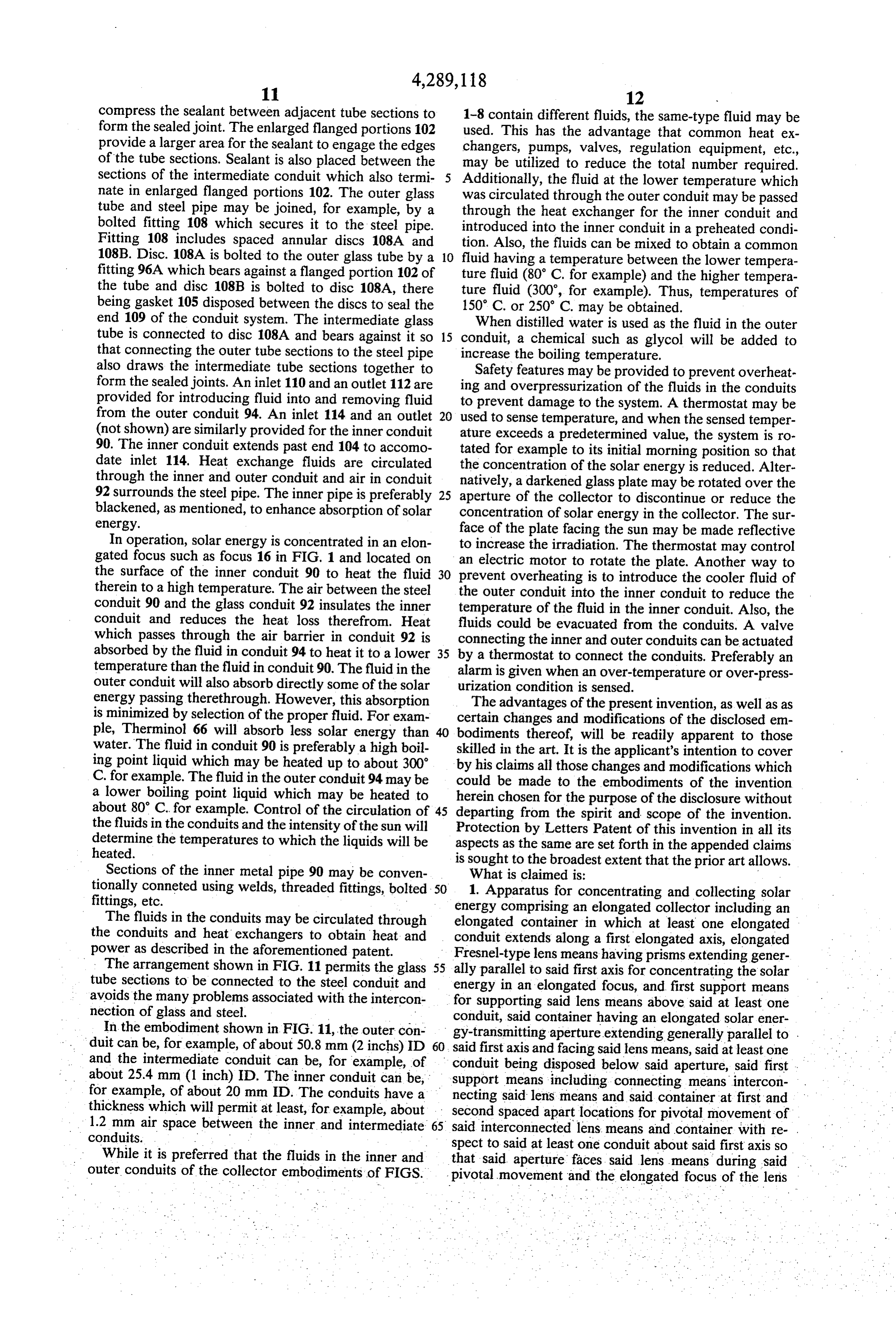
compress the sealant between adjacent tube sections to 1-8 contain different fluids, the same-type fluid may be form the sealed joint. The enlarged flanged portions 102 used. This has the advantage that common heat ex provide a larger area for the sealant to engage the edges changers, pumps, valves, regulation equipment, etc., of the tube sections. Sealant is also placed between the may be utilized to reduce the total number required. sections of the intermediate conduit which also termi Additionally, the fluid at the lower temperature which nate in enlarged flanged portions 102. The outer glass was circulated through the outer conduit may be passed tube and steel pipe may be joined, for example, by a through the heat exchanger for the inner conduit and bolted fitting 108 which secures it to the steel pipe. introduced into the inner conduit in a preheated condi Fitting 108 includes spaced annular discs 108A and tion. Also, the fluids can be mixed to obtain a common 108B. Disc. 108A is bolted to the outer glass tube by a 10 fluid having a temperature between the lower tempera fitting 96A which bears against a flanged portion 102 of ture fluid (80° C. for example) and the higher tempera the tube and disc 108B is bolted to disc 108A, there ture fluid (300', for example). Thus, temperatures of being gasket 105 disposed between the discs to seal the 150° C. or 250 C. may be obtained.
end 109 of the conduit system. The intermediate glass When distilled water is used as the fluid in the outer tube is connected to disc 108A and bears against it so 15 conduit, a chemical such as glycol will be added to that connecting the outer tube sections to the steel pipe increase the boiling temperature.
also draws the intermediate tube sections together to Safety features may be provided to prevent overheat form the sealed joints. An inlet 110 and an outlet 112 are ing and overpressurization of the fluids in the conduits provided for introducing fluid into and removing fluid to prevent damage to the system. A thermostat may be from the outer conduit 94. An inlet 114 and an outlet used to sense temperature, and when the sensed temper (not shown) are similarly provided for the inner conduit ature exceeds a predetermined value, the system is ro 90. The inner conduit extends past end 104 to accomo tated for example to its initial morning position so that date inlet 114. Heat exchange fluids are circulated the concentration of the solar energy is reduced. Alter through the inner and outer conduit and air in conduit natively, a darkened glass plate may be rotated over the 92 surrounds the steel pipe. The inner pipe is preferably 25 aperture of the collector to discontinue or reduce the blackened, as mentioned, to enhance absorption of solar concentration of solar energy in the collector. The sur energy. face of the plate facing the sun may be made reflective In operation, solar energy is concentrated in an elon to increase the irradiation. The thermostat may control gated focus such as focus 16 in FIG. 1 and located on an electric motor to rotate the plate. Another way to the surface of the inner conduit 90 to heat the fluid 30 prevent overheating is to introduce the cooler fluid of therein to a high temperature. The air between the steel the outer conduit into the inner conduit to reduce the conduit 90 and the glass conduit 92 insulates the inner temperature of the fluid in the inner conduit. Also, the conduit and reduces the heat loss therefrom. Heat fluids could be evacuated from the conduits. A valve which passes through the air barrier in conduit 92 is connecting the inner and outer conduits can be actuated absorbed by the fluid in conduit 94 to heat it to a lower 35 by a thermostat to connect the conduits. Preferably an temperature than the fluid in conduit 90. The fluid in the alarm is given when an over-temperature or over-press outer conduit will also absorb directly some of the solar urization condition is sensed.
energy passing therethrough. However, this absorption The advantages of the present invention, as well as as is minimized by selection of the proper fluid. For exam certain changes and modifications of the disclosed em ple, Therminol 66 will absorb less solar energy than bodiments thereof, will be readily apparent to those water. The fluid in conduit 90 is preferably a high boil skilled in the art. It is the applicant's intention to cover ing point liquid which may be heated up to about 300 by his claims all those changes and modifications which C. for example. The fluid in the outer conduit 94 may be could be made to the embodiments of the invention a lower boiling point liquid which may be heated to herein chosen for the purpose of the disclosure without about 80 C. for example. Control of the circulation of 45 departing from the spirit and scope of the invention. the fluids in the conduits and the intensity of the sun will Protection by Letters Patent of this invention in all its determine the temperatures to which the liquids will be aspects as the same are set forth in the appended claims heated. is sought to the broadest extent that the prior art allows. Sections of the inner metal pipe 90 may be conven What is claimed is:
tionally conneted using welds, threaded fittings, bolted 50 1. Apparatus for concentrating and collecting solar fittings, etc. energy comprising an elongated collector including an The fluids in the conduits may be circulated through elongated container in which at least one elongated the conduits and heat exchangers to obtain heat and conduit extends along a first elongated axis, elongated power as described in the aforementioned patent. Fresnel-type lens means having prisms extending gener The arrangement shown in FIG. 11 permits the glass 55 ally parallel to said first axis for concentrating the solar tube sections to be connected to the steel conduit and energy in an elongated focus, and first support means avoids the many problems associated with the intercon for supporting said lens means above said at least one nection of glass and steel. conduit, said container having an elongated solar ener In the embodiment shown in FIG. 11, the outer con gy-transmitting aperture extending generally parallel to . duit can be, for example, of about 50.8 mm (2 inchs) ID 60. said first axis and facing said lens means, said at least one and the intermediate conduit can be, for example, of conduit being disposed below said aperture, said first about 25.4 mm (1 inch) ID. The inner conduit can be, support means including connecting means intercon for example, of about 20 mm ID. The conduits have a necting said lens means and said container at first and thickness which will permit at least, for example, about - second spaced apart locations for pivotal movement of 1.2 mm air space between the inner and intermediate 65 said interconnected lens. means and container with re conduits. spect to said at least one conduit about said first axis so While it is preferred that the fluids in the inner and that said aperture faces said lens means during said outer conduits of the collector embodiments of FIGS. pivotal movement and the elongated focus of the lens
Page 16
means is located substantially in or on and substantially axis, each for concentrating the solar energy in an elon along said at least one conduit, the products of the gated focus, a central Fresnel-type lens having prisms weights times the distances of components above and below said first axis being substantially equal whereby extending ond substantially parallel to said first axis, a sec
Fresnel-type lens adjacent to one end of said central the moments above and below said first axis are substan tially equal and said apparatus is substantially balanced same direction as and
Fresnel-type lens having prisms extending in the about said first axis, said apparatus further conprising inclined downwardly atprisms the of said central lens and second support means for supporting the intercon collector, and a third Fresnel-typetheretoan angle towards said lens adjacent to the nected container and lens means between said first and other end of said central Fresnel-type lens and having second locations for pivotal movement of the intercon 10 prisms nected lens means and container about an axis trans extending in the same direction as the prisms of verse to said first axis. said central Fresnel-type lens and inclined downwardly 2. The apparatus as recited in claim 1, wherein said at an angle thereto towards said collector and opposed first support means includes an elongated frame sup to said second Fresnel-type lens, first supporting means porting said first pivot means, and said second support 15 for supporting said lens means above said at least one conduit, said container having an elongated solar ener means includes second pivot means pivotally connect gy-transmitting ing said elongated frame to said first support means so aperture extending generally parallel to that said interconnected container and lens means and said first axis and facing said lens means, said at least one said at least one conduit are pivotal about said trans conduit being disposed below said aperture, said first verse axis. 20 support means including connecting means intercon 3. The apparatus as recited in claim 1, wherein said necting said lens means and said container for pivotal apparatus is disposed so that said first axis extendsgen-' movement of said interconnected lens means and con erally in the east-west direction, whereby said intercon tainer with respect to said at least one conduit about nected container and lens may be pivoted by said first said first axis so that said aperture faces said lens means support means to track the sun on a daily basis and by 25 during said pivotal movement and the elongated focus said second support means to track the sun on a seasonal of at least one of the Fresnel-type lenses is located sub basis. stantially in or on and substantially along said at least 4. Apparatus for concentrating and collecting solar one conduit, the products of the weights times the dis energy comprising an elongated collector including an tances of components above and below said first axis elongated container in which at least one elongated 30 being substantially equal whereby the moments above conduit extends along a first elongated axis, lens means and below said first axis are substantially equal and said comprising at least three elongated Fresnel-type lenses apparatus is substantially balanced about said first axis. having prisms extending generally parallel to said first sk k s :k
Page 17
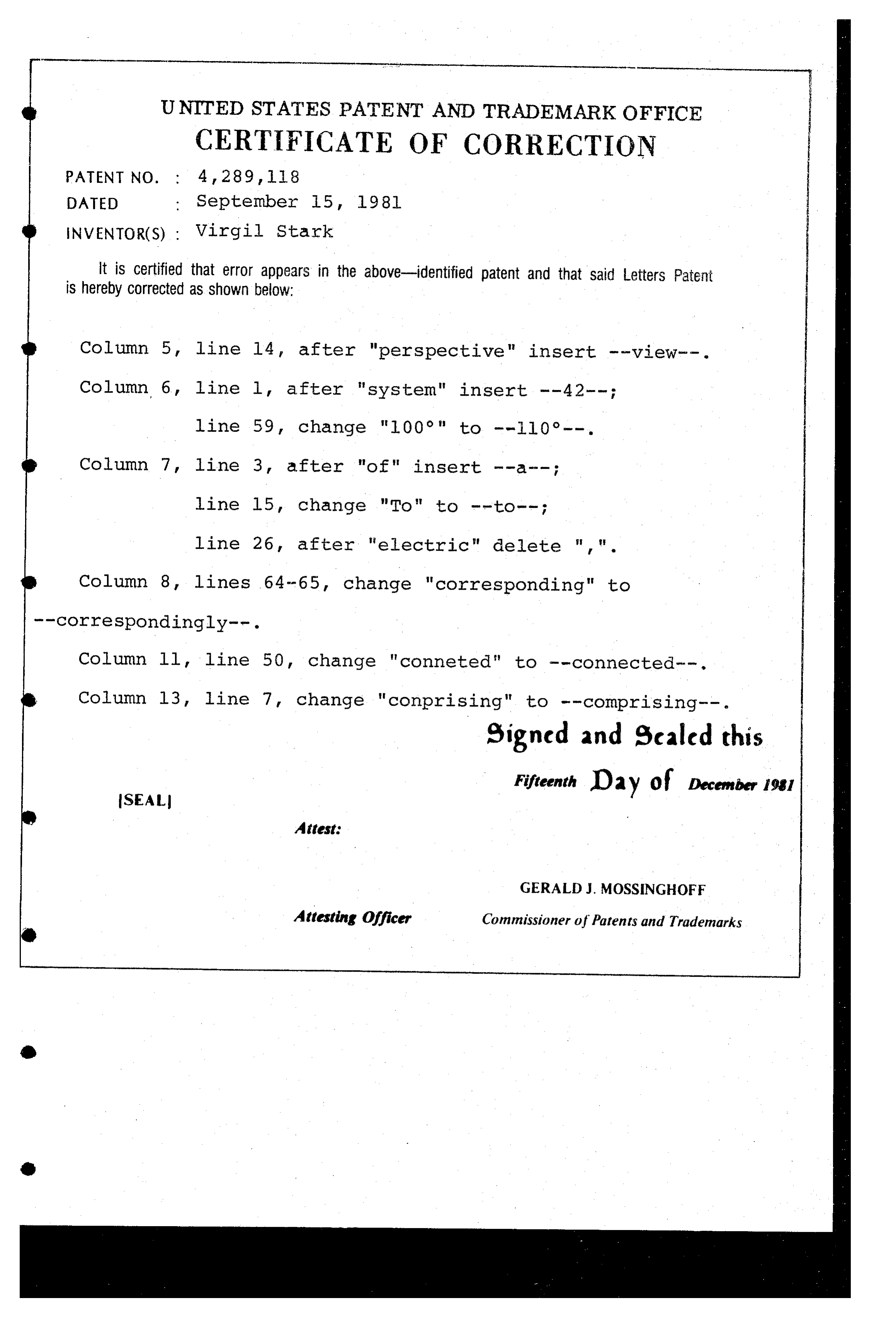
UNITED STATES PATENT AND TRADEMARK OFFICE
CERTIFICATE OF CORRECTION
INVENTOR(S) : Virgil Stark it is Certified that error appears in the above-identified patent and that said Letters Patent is hereby corrected as shown below:
Column 5, line 14, after "perspective" insert --View -- . Column 6, line 1, after "system" insert --42--;
Column 7, line 3, after "of" insert --a--;
line 15, change "To" to --to--;
line 26, after "electric" delete " , ".
Column 8, lines 64-65, change "corresponding" to
Column ll, line 50, change "conneted" to -- connected". Column 13, line 7, change "conprising" to -- Comprising . eigned and scaled this
Fifteenth Day of December 1981
GERALD J MOSSINGHOFF
Attesting Officer Commissioner of Patents and Trademarks
Provenance
- Collection
- Cited prior art
- Original PDF
- patentimages.storage.googleapis.com →
- Filed
- 1978-06-29
- Pages
- 17
- Method
- pdftotext (the PDF's own text layer) + pdftoppm 300dpi page scans
- Source
- Google Patents bibliographic record
- Granted
- 1981-09-15
- Inventors
- Virgil Stark; North American Utility Construction Corp
- Transcribed from
- patentimages.storage.googleapis.com →