patent · US20110214665A1
Tracking Fiber Optic Wafer Concentrator
8 September 2011
Page 1 — bibliographic record
(19) United States (12) Patent Application Publication (10) Pub. No.: US 2011/0214665 A1
Raymond et al. (43) Pub. Date: Sep. 8, 2011 (54) TRACKING FIBER OPTICWAFER Publication Classification CONCENTRATOR (51) Int. Cl
(75) Inventors: Mark A. Raymond, Littleton, CO F24, 2/24 (2006.01) (US); Howard G. Lange, Mount F24. 2/38 (2006.01)
Prospect, IL (US):
Cherry Hills Seth
Village, COWeiss,
(US) (52) U.S. Cl. .......................... 126/600: 126/651: 126/698
(73) Assignee: GENELENS A Solar power system for Supplying concentrated Solar TECHNOLOGIES, LLC, energy. The system includes a cylindrical absorber tube car Englewood, CO (US) rying the working fluid and a concentrator assembly, which includes an array of linear lenses such as Fresnel lenses. The (21) Appl. No.: 13/108,425 concentrator assembly includes a planar optical wafer paired with each of the linear lenses to direct light, which the lenses (22) Filed: May 16, 2011 focus on a first edge of the wafers, onto the collector via a second or output edge of the wafers. Each of the optical
Related U.S. Application Data wafers is formed from a light transmissive material and acts as a light "pipe. The lens array is spaced apart a distance from (63) Continuation of application No. 12/888.584, filed on the first edges of the optical wafers. This distance or lens array Sep. 23, 2010, now Pat. No. 7.946,286. height is periodically adjusted to account for seasonal changes in the Sun's position, such that the focal point of each (60) Provisional application No. 61/245,507, filed on Sep. linear lens remains upon the first edge of one of the optical 24, 2009. wafers yearlong.
WLENS
ARRAY OF GT
WAFERSIPPES
4. POWER
- Y-C www. THERMAL
-1 to 12 WORKINGIRANSFER STORAGE
JBE
Page 2
Drawing sheet — no readable text.
Page 3
Drawing sheet — no readable text.
Page 4
Drawing sheet — no readable text.
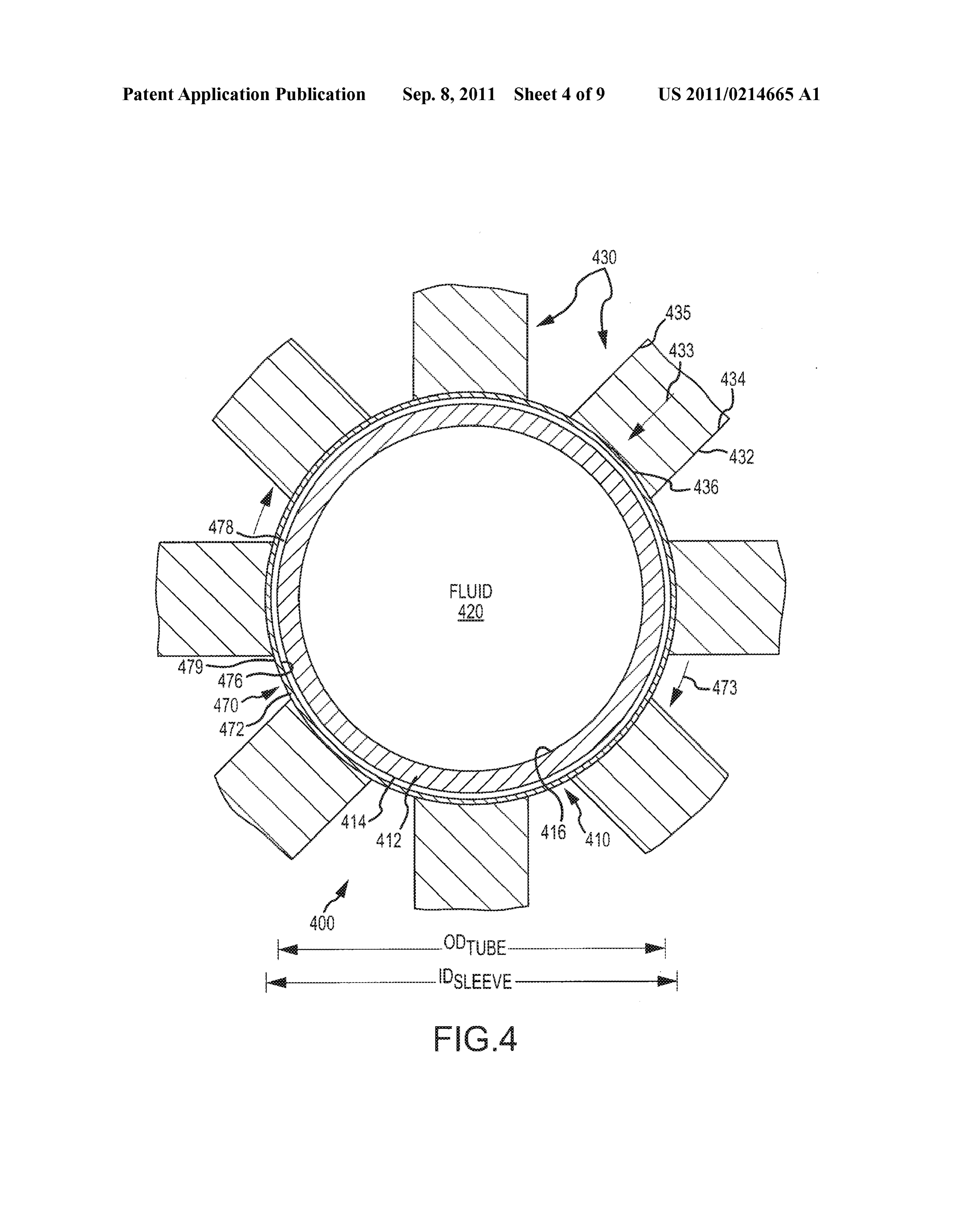
Page 5
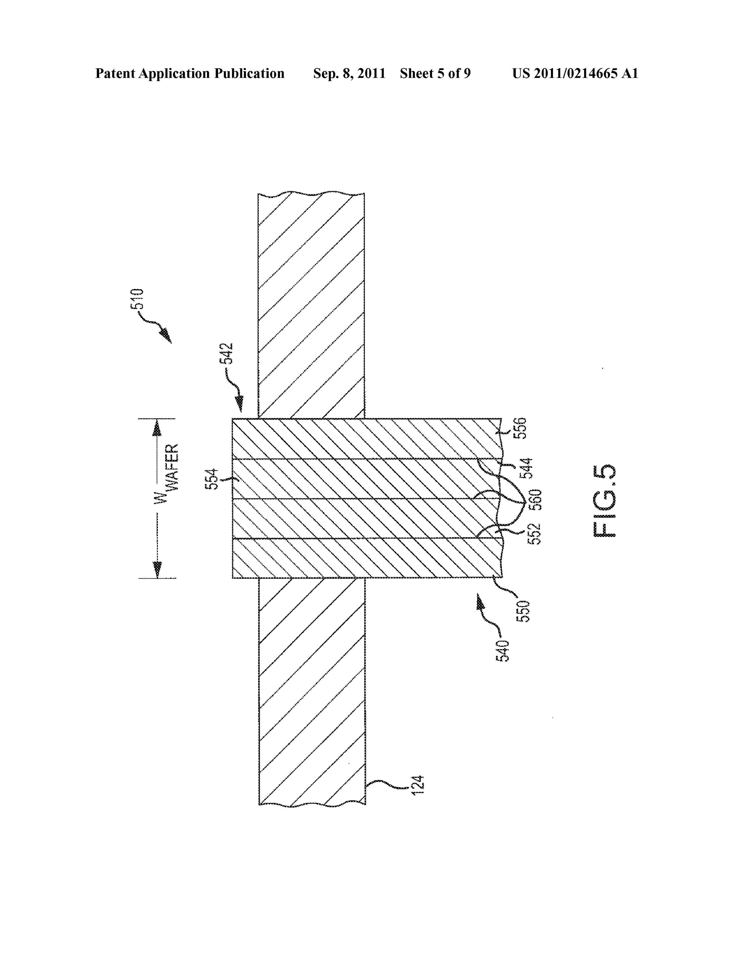
Drawing sheet — no readable text.
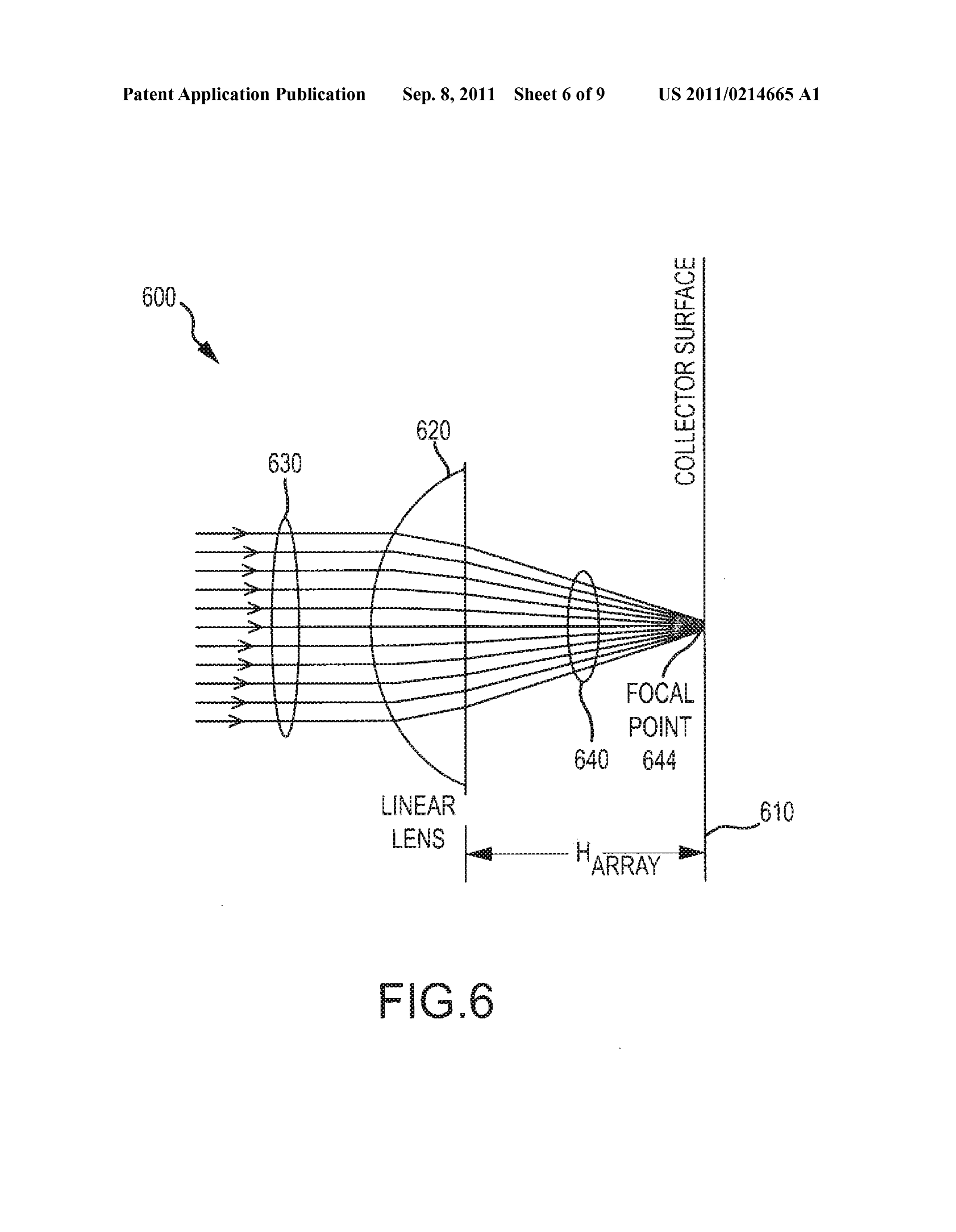
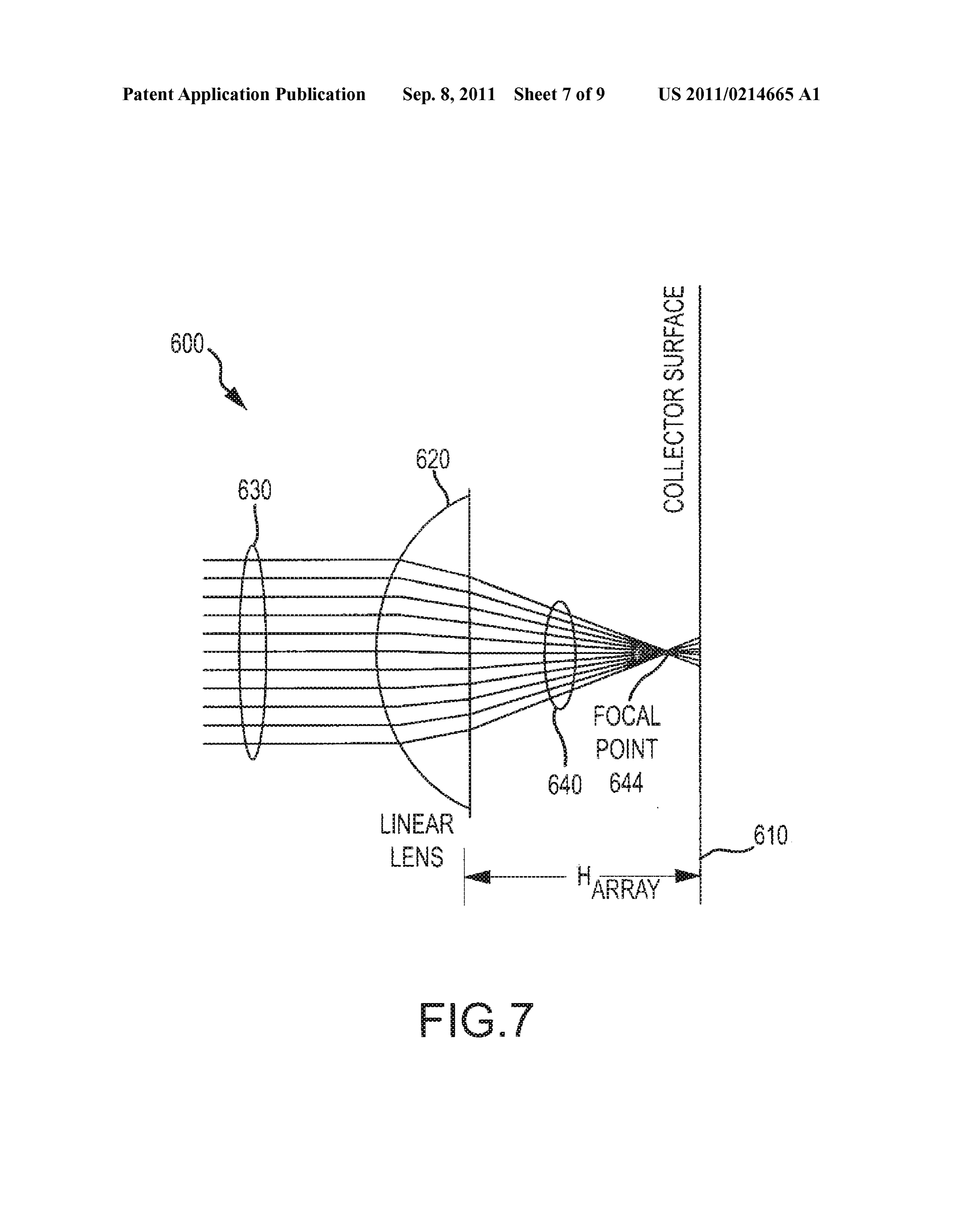
Page 6
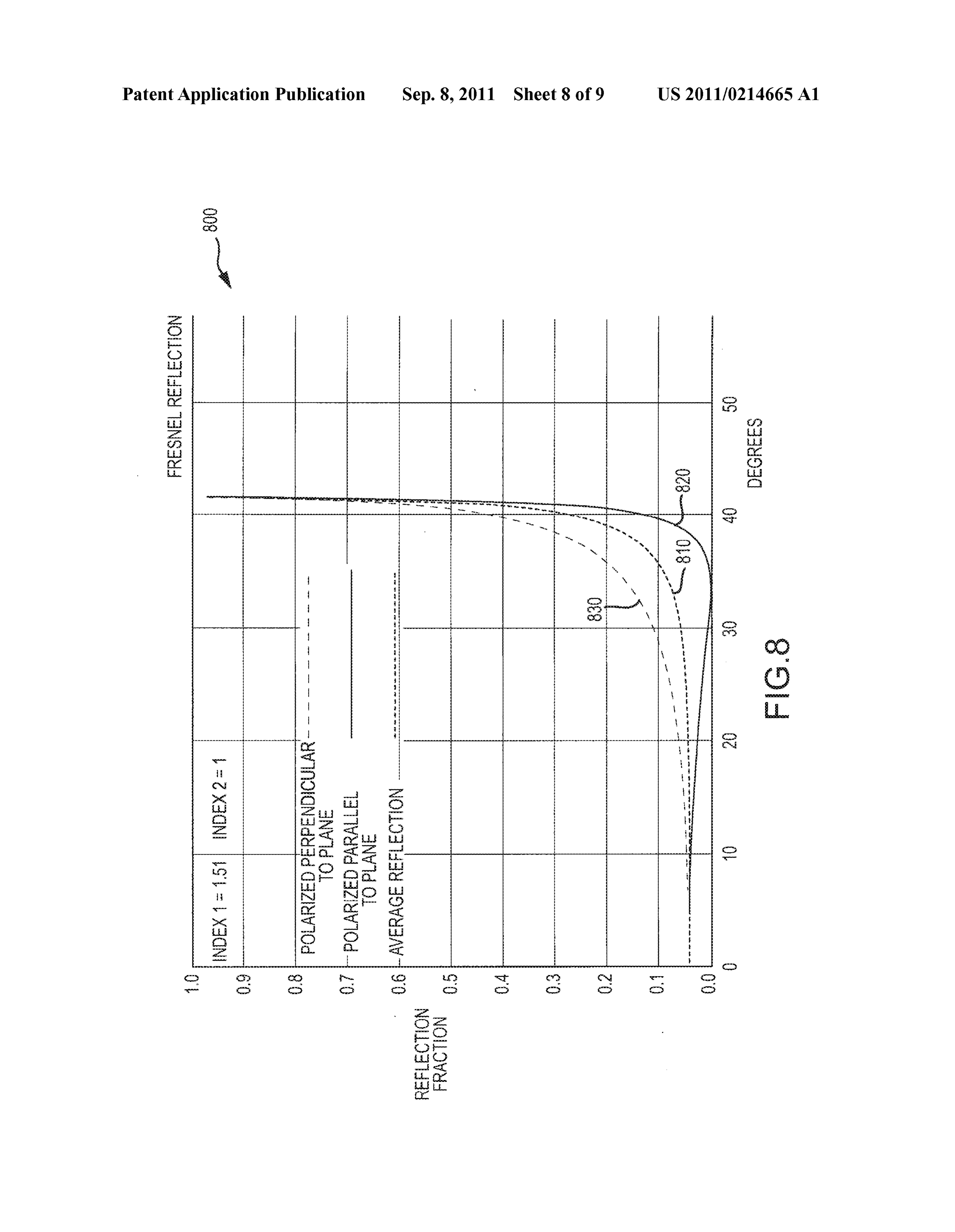
Drawing sheet — no readable text.
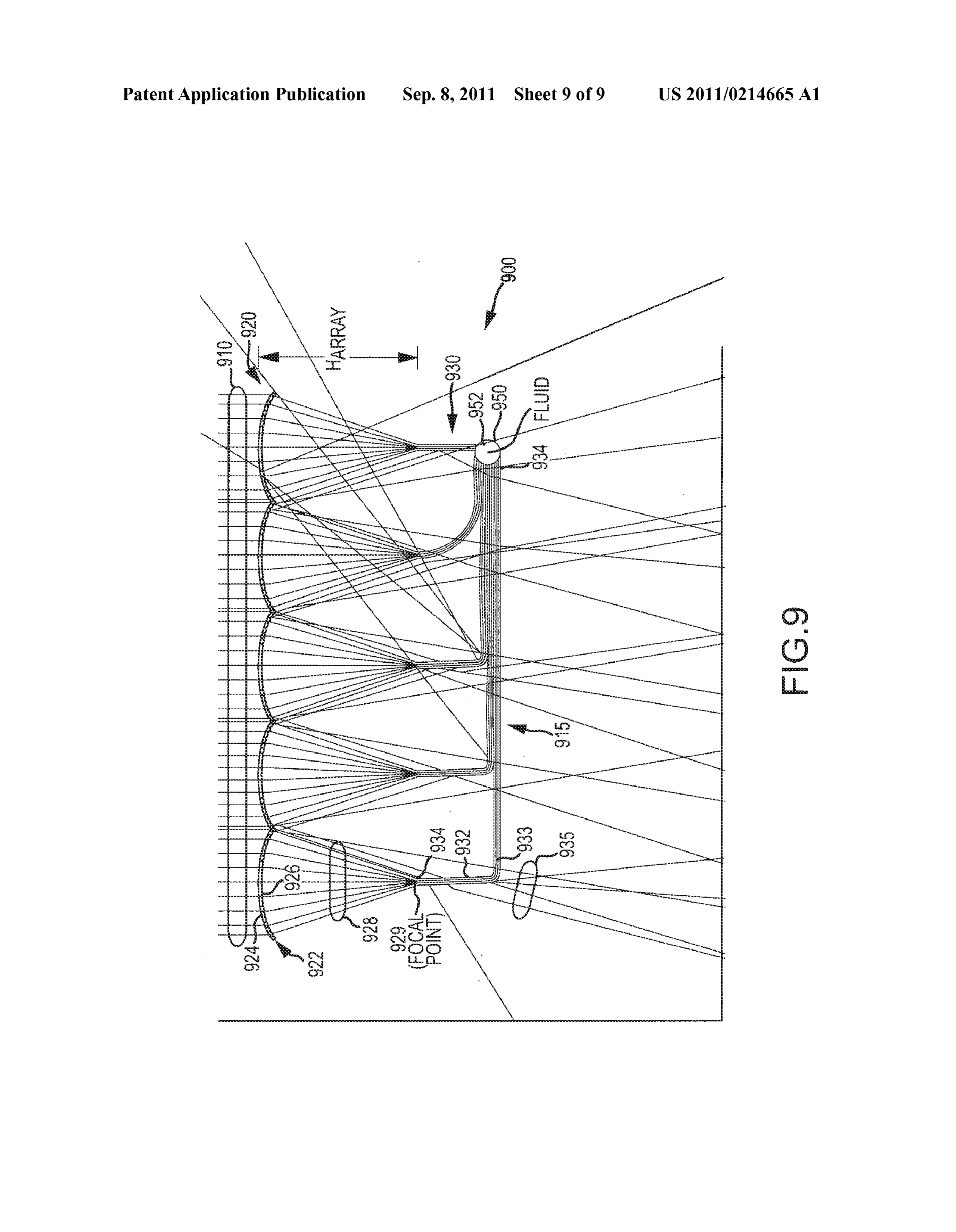
Page 7
Drawing sheet — no readable text.
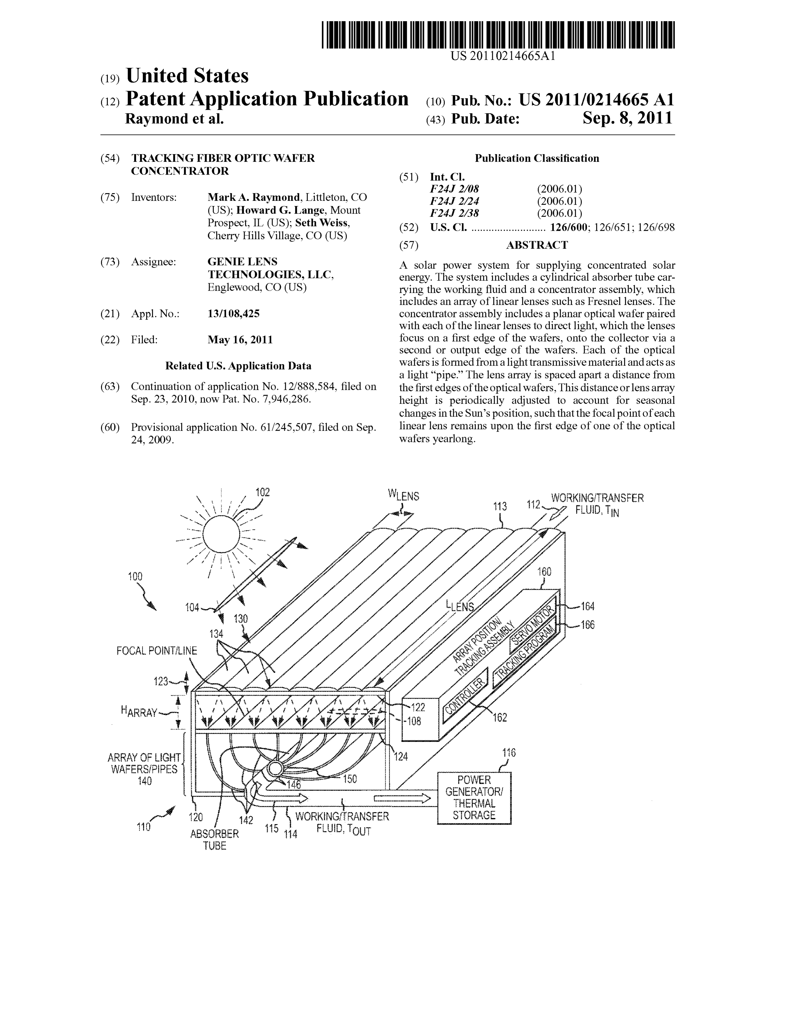
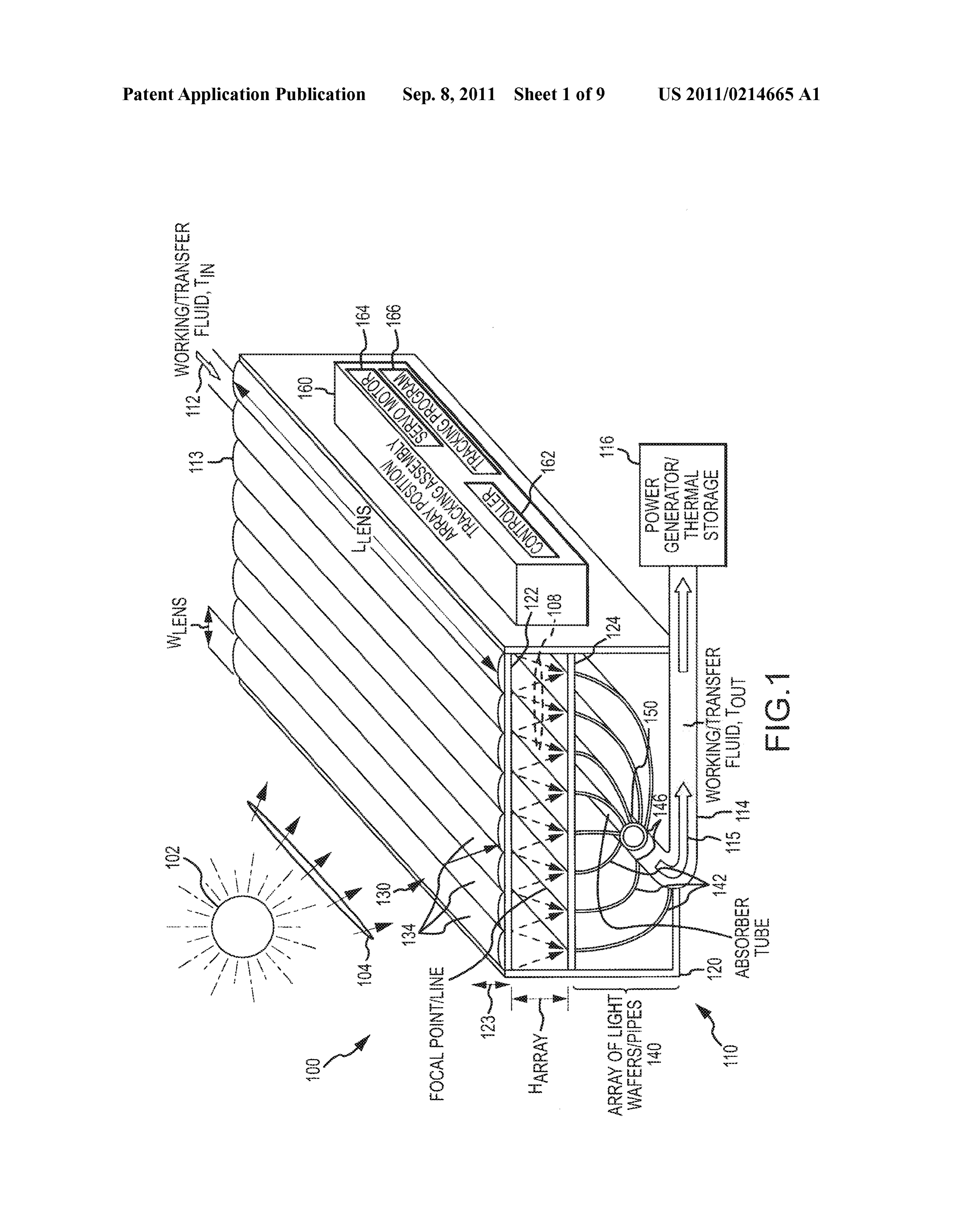
Page 8
Drawing sheet — no readable text.
Page 9
Drawing sheet — no readable text.
Page 10
Drawing sheet — no readable text.
Page 11
US 2011/0214665 A1 Sep. 8, 2011
TRACKING FIBER OPTC WAFER focused to heat an absorber tube made of tempered glass and CONCENTRATOR containing water, oil, or the like that is pumped through the tube (which is generally 5 to 10-inches in diameter) at the
CROSS-REFERENCE TO RELATED correct rate depending upon the length of the concentrator APPLICATIONS and corresponding to the overall size of the system. 0001. This application is a continuation of U.S. patent 0008 While being desirable for using a renewable power application Ser. No. 12/888,584, filed Sep. 23, 2010, which Source, CST Systems, such as those that utilize parabolic claims the benefit of U.S. Provisional Application No. concentrators with single-axis tracking capabilities, have not 61/245,507 filed Sep. 24, 2009, both of which are incorpo been widely adopted. One drawback with CST systems is that rated herein by reference in their entireties. they tend to be quite inefficient, and this lack of efficiency is especially acute during months where the incidence angle of
BACKGROUND OF THE INVENTION the sun is the furthest from perpendicular. Collecting efficien 0002 1. Field of the Invention cies due to the skewed focus of the troughs can drop to under 0003. The present invention relates, in general, to concen fifty percent in these conditions. In addition, the absorber tube trators for use in the Solar power industry, and, more particu or pipe carrying the heated fluid may be relatively large in larly, to systems, devices and methods for more effectively diameter and is located directly in front of the concentrator concentrating Solar energy (or, more simply, for concentrat (i.e., in the trough of the parabolic reflector or the like), which ing Sunlight) using an improved tracking concentrator Such as shadows the overall collection device and decreases effi a fiber optic wafer concentrator adapted for effective tracking ciency further. Efficiencies of CST systems area concern as of the Sun. the overall efficiencies from collector to grid may be as low as 0004 2. Relevant Background about fifteen percent. Hence, there is a need to enhance effi 0005. In general, concentrated solar power systems use ciencies at each step of the process including collection and lenses or mirrors to focus a large area of sunlight onto a small thermal efficiencies proximate or within the collector assem area. Electrical power is produced when the concentrated bly.
light is directed onto photovoltaic Surfaces or when the con 0009. Additional drawbacks of conventional parabolic centrated light is used to heat a transfer fluid for a conven concentrators include expense of manufacturing, lack of effi tional power plant (e.g., to run a turbine with Steam). ciency during many months of the year (e.g., due to non ideal 0006 With regard to the latter example, thermal concen azimuth angles), and fragility of the parabolic trough mate trators have been around for many years, with concentrated rials (e.g., which may lead to damage under normal operating solar thermal (CST) being used to produce renewable heat or conditions such as due to weather conditions including hail, electricity (which may be labeled thermoelectricity as it is strong winds, and the like). In addition, parabolic reflectors or usually generated via Steam generation). A wide range of concentrators tend to be quite dangerous to work around concentrating technologies exists with a parabolic trough during Sunlight hours as they produce concentrated beams of being a popular choice for use in many CST systems. A parabolic trough includes a linear parabolic reflector that Sunlight that can cause severe burns and even blindness and as concentrates light onto a receiver that is positioned along the many of the parts of the system are at very high operating reflector's focal line. The receiver is typically a pipe or tube temperatures.
(i.e., is an absorber tube) positioned directly above the middle 0010 Further, one of the larger drawbacks is the need to of the parabolic reflector (or mirrored surface that may be a maintain the reflector and absorbertubing outer Surfaces in a coating of silver, polished aluminum, or the like). The pipe or very clean state to maintain light collection and thermal effi tube is filled with a working or transfer fluid. The reflector is ciencies in desired ranges. As a result, a problem with para operated to attempt to accurately track the Sun's movements bolic concentrators is the difficulty of cleaning the systems during daylight hours by tracking along a single axis. In some including the large usage of cleaning chemicals and water. cases, the working fluid is an oil, a molten salt, or other Large systems require constant cleaning and rinsing, adding material that is heated to high temperatures (300 to 700°F.) as costs and, over time, contaminating soil underneath the it flows through the receiver, and fluid is then used as a heat reflectors. In desert conditions where many CST systems are Source for a power generation system (e.g., to heat water to located, it is particularly expensive and difficult to provide create Steam that is used to turn a turbine generator or the water for cleaning these units. Most arrays are cleaned by like). crews on an ongoing basis or seven days a week, which 0007. There is a strong desire to expand the use of renew increases the maintenance or operating costs associated with able energy sources such as thermal concentrators. As dis generation of electricity with CST systems. cussed above, CST systems generally track the Sun east to west from the morning to evening hours, and this is done with 0011 Hence, there remains a need for a more modem, a complex tracking system that tilts a linear parabolic con Scalable concentrator System. Preferably, Such a concentrator centrator or reflector, which may be may several hundred system would be easier to clean including using less water meters long and up to as much as ten or meters across. Gen and chemicals. The system may be cheaper to manufacture erally, the lines or solar filed piping/absorber tubing of these and less dangerous to operate and maintain (and more durable systems are linked together to heat water and in turn generate Such as being less likely to be damaged by hail or the like). steam to drive a turbine generator to provide electricity. The Further, the concentrator system may be more efficient (with parabolic concentrators are generally made of glass with a a lower cost per watt of generated electricity). Still further, the mirror backing material and include a sturdy framing system concentrator System may be useful for heating a variety of that is positioned or controlled with a computerized one axis transfer or working fluids including heating oil, glycol, air, or tracking system. The parabolic concentrators are generally other liquids and also have the ability to function as a photo

Page 12
US 2011/0214665 A1 Sep. 8, 2011
Voltaic concentrator at the same time or independently from creation of steam to run turbines or other power generation heating a working or transfer fluid. devices in Scale for conventional or thermal storage power plants.
SUMMARY OF THE INVENTION 0016. In other CSP systems, desert towers are used to 0012. The present invention addresses the above and other create a great deal of heat by using mirrors positioned around problems by providing a concentrator for a Solar energy sys a tower to focus toward the tower. Unfortunately, these sys tem (e.g., a concentrated Solar power (CSP) system) Such as a tems are very expensive to fabricate and maintain as well as scalable, linear Fresnel collector system or assembly that uses being relatively dangerous to operate. Further, tower-based fiber optic wafers or pipes. It is believed Such as a concentra CSP systems require a great deal of land (e.g., have a large tor will cost significantly less than conventional parabolic footprint or land-use profile) and require significant amounts trough collectors while providing efficiencies of fifty percent and nearly continuous maintenance to continue to operate or, more likely, higher efficiencies. near or in design efficiency ranges. 0013 Concentrators for use with solar technologies, 0017. In some cases. Fresnel lenses have shown promise including concentrated Solar power (CSP) systems, are for use in concentrators. The use of lenses have led to Scaling becoming increasingly efficient and are being used primarily problems, though, as concentration ratios in linear collectors for concentrating Sunlight to create heat for generating elec are limited (e.g., 300 to 1), and larger lenses (including tricity. CSP systems producing electricity using heat (rather Fresnel lenses) have extremely long focal lengths that are than photovoltaic (PV) surfaces) typically are configured to difficult to manage or manipulate with conventional tracking generate heat Sufficient to create steam, which, in turn, is used as found in parabolic trough collectors. For example, some of to drive a turbine or Sterling engine to generate electricity. larger Fresnel lenses may have focal lengths of 40 feet or Most concentrators, such as parabolic trough concentrators, more and are assembled in pieces. To get the power to one provide limited efficiencies, have high associated manufac spot location, Such large Fresnel lenses may have to be turing and maintenance costs, and utilize mirrors rather than mounted high in the sky to focus on a "spot location, and, in lenses to concentrate sunlight. In the majority of these CSP the past, there had been no way to consolidate the heat with systems, the collector or receiver (or absorbertube) is located adjoining lens arrays. Since parabolic troughs cannot reach in front of the minored surfaces of the reflector and causes ideal temperatures for making steam (e.g., ideally, tempera shadowing, which leads to decreased efficiencies. High qual tures in excess of 1000 F) and towers do not integrate well ity minors or reflectors are also very expensive to manufac into existing coal or natural gas plants, there has not been an ture and require a great deal of maintenance (e.g., cleaning) to ideal concentrator available within the solar energy industry. maintain their reflectivity. Most of the existing CSP technolo 0018. The inventors recognized the need for a new type of gies utilize trough or dish technologies, and both of these collector or “concentrator that may be used for thermal collector technologies have marginal efficiencies and present power generation, in thermal PV systems, and concentrator problems for collecting thermal energy from the Sun over PV systems. To this end, the inventors propose a concentrator differing seasons and even during a single day's time. for a Solar energy system (e.g., a concentrated Solar power 0014 Traditional trough collectors may have several Sun (CSP) system) such as a scalable, linear Fresnel collector light or ray “bounces’ before the rays hit the linear collector system or assembly that uses fiber optic wafers or pipes. The or absorber tube. The trough may be fixed in place but, more concentrator may be thought of as a tracking, integrated lens typically, a tracking system or assembly is provided to move and optical wafer concentrator (or a Fresnel lens-based track the large trough to better track the changing position of the ing concentrator utilizing fiber optic wafers or pipes). The Sun and direct a larger percentage of received Sunlight onto described concentrator (and CSP systems including Such a the linear collector or absorber tube. Generally, trough col concentrator) solves economic issues, Scalability issues, tem lectors use a single-axis tracking system to modify or adjust perature issues, and other issues associated with prior Solar orientation of the trough in the east to west direction (e.g., collector technologies while allowing easy integration of the attempt to follow the Sun's movement across the sky in day concentrator into gas plants and coal plants. light hours). Parabolic trough collectors may have maximum 0019 More particularly, a solar power system is provided ray collection efficiencies (which may also be measured as for Supplying concentrated Solar energy, Such as via a work thermal efficiencies) of about 60 to 80 percent with net effi ing or transfer fluid or via PV materials or devices, to a power ciencies of about fifty percent or less after reflectivity deduc generator or thermal storage. The system includes a collector tions, shadowing and off azimuth angle averages during the and a concentrator assembly. The concentrator assembly year are fully considered. A further concern is that the trough includes an array of two or more linear lenses (such as planar designs often have to be limited to a particular size and or arched linear Fresnel lenses with a width of 4 to 10 inches particular concentration ratios. or more and a length extending along the concentrator). The 0015. Due, in part, to these limits associated with para concentrator assembly also includes a set of optical wafers bolic trough collectors, other collectors have been designed each having a planar body and each being paired with one of and implemented in CSP systems but with limited success. the linear lenses to direct light focused by the corresponding For example, dish collectors have been used in CSP systems. lenses onto the collector. Specifically, a first edge of the body Dish collectors provide two axes of tracking that provide an of the optical wafers is supported in the concentrator assem advantage over the single-axis tracking of trough systems as bly to be proximate to the array of linear lenses (e.g., Sup it allows adjustments to be more readily made for seasonal ported by a Support plate with a linear edge facing toward one changes in the Sun's location. However, dish collectors of the lenses). Additionally, a second edge of the body of the present scaling and other problems. The mirrors for the dish optical wafers (opposite the first edge) is positioned proxi shaped reflector or collector are difficult to build economi mate to the collector, and each of the linear lenses focuses cally. Also, there is presently not a practical Solution for received sunlight onto the first edge of the paired one of the linking more than one unit together Such as to facilitate the optical wafers. In this manner, a portion of the Sunlight
Page 13
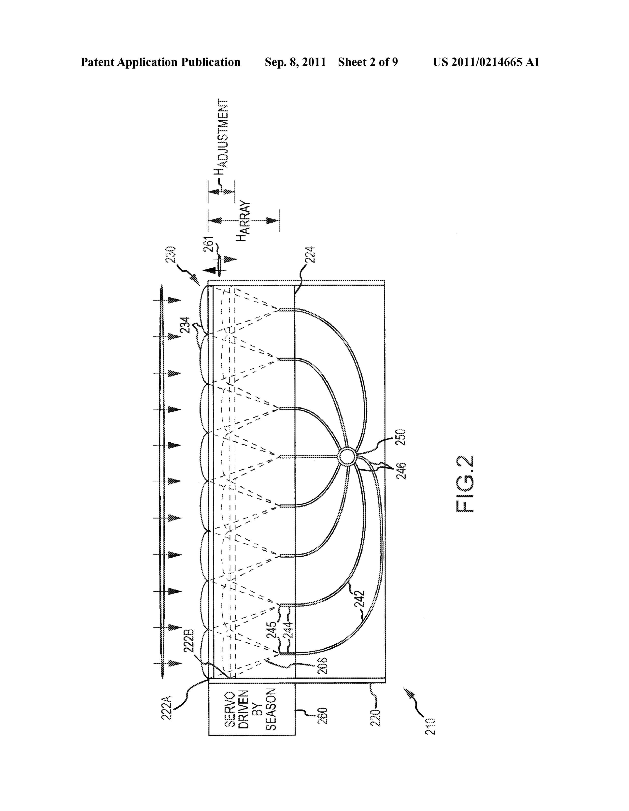
US 2011/0214665 A1 Sep. 8, 2011
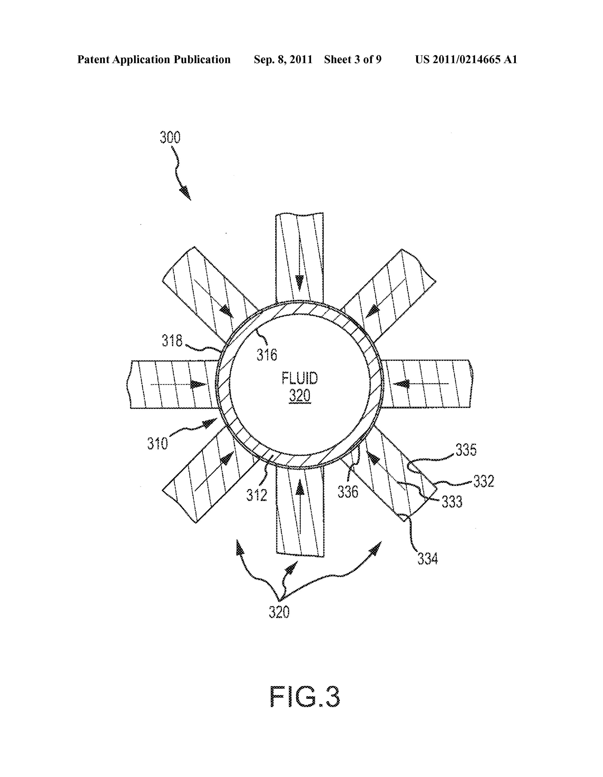
focused by each lens on an edge of the optical wafer is 0024 FIG. 2 illustrates an end view of another embodi transmitted through the optical wafers to the collector (and ment of a concentrator assembly such as may be used in the out the second edges of the wafers that act as light pipes for CSP system of FIG. 1 or other CSP systems: the concentrated Sunlight or Solar energy). 0025 FIG. 3 is a sectional end view of a collector assem 0020. In some embodiments, each of the bodies of the bly showing its star-like appearance due to the positioning of optical wafers is formed from a light transmissive material 2 to 12 or more light pipes or wafers (with 8 shown in this (such as a plastic, glass, or ceramic), and the focused Sunlight non-limiting example) about a circumference of a collector or that enters the body at the first edge is retained within the body absorber tube:
using total internal reflection. The lens array may be spaced 0026 FIG. 4 illustrates a collector assembly in a sectional apart from the first edges of the bodies of the optical wafers by view showing use of a shell/sleeve to support second/output a lens array height, and this lens array height is selected based ends of light wafers proximate to an absorbertube or collector on a configuration of the linear lenses Such that a focal point while allowing the shell to rotate with tracking in a concen for each of the linear lenses is proximate to one of the first trator assembly;
edges along a length of the concentrator assembly (e.g., light 0027 FIG. 5 shows an embodiment of a light wafer that is for each lens is focused along a line that coincides with the a composite design including two or more planar sheets of first edge of a paired/corresponding light, wafer). Signifi material to create a wafer with increased width to provide an cantly, the lens array is positionable within the concentrator enlarged or wider light-receiving Surface at an end or edge of assembly to adjust the lens array height such that the focal the light wafer;
points of the linear lenses substantially coincide with one of 0028 FIGS. 6 and 7 illustrate ray tracing plots for a por the first edges of the optical wafers to cause the focused tion of concentrator assembly with a fixed array height but Sunlight to enter the optical wafers. For example, the concen light at two differing seasonal Sun positions; trator assembly may include an array positioning mechanism 0029 FIG. 8 is a plot indicating a fraction of light reflected or assembly adapted to provide two-axis tracking of the lens Versus incidence angles in a light wafer illustrating aspects of array including tracking a position of the Sun during daytime total internal reflection utilized in the present invention; and hours and periodically adjusting the lens array height based 0030 FIG. 9 is a ray tracing of an embodiment of a con on the Sun's azimuth to match a focal length of the linear centrator assembly useful for showing the effectiveness of the lenses to the array height. light wafers in collecting/receiving focused light and then 0021. In some embodiments, each of the linear lenses is adjoining the wafers to a collector to concentrate Sunlight, substantially identical in configuration and is a linear Fresnel e.g., to heat a transfer or working fluid in an absorber tube. lens. More particularly, the system may have an array of DETAILED DESCRIPTION OF THE PREFERRED lenses including at least eight of linear Fresnel lenses (e.g., EMBODIMENTS arched Fresnel lenses with the flat side facing outward to facilitate cleaning). In some cases, the collector includes an 0031. The present invention is generally directed toward absorber tube or pipe with a light-transmissive sidewall (e.g., new concentrators or collectors for more effectively collect glass, plastic, or ceramic material cylindrical sidewall) ing Solar energy throughout the day and over two or more through which a Volume of working fluid flows during opera seasons. FIG. 1 illustrates schematically (or in functional tion of the Solar power system. Then, the second edge of each block form) a concentrated solar power (CSP) system 100 of of the bodies of the optical wafer is positioned about a cir one embodiment. As shown, the CSP system 100 includes a cumference of the sidewall to target the portion of the focused concentrator or collector assembly 110 that combines a lens Sunlight into the working fluid (e.g., eight to twelve or more array with a set or array of light wafers, and the concentrator planar wafers may be positioned equidistally about the cir assembly 110 may be tracking and/or have the lens array be cumference of the absorbertube to target the flowing working adjustable to adjust for daily and/or seasonal changes in the fluid from eight differing angles to more readily/equally heat position of the Sun 102.
the working/transfer fluid). 0032 Briefly, the CSP system 100 includes the concentra 0022. In some embodiments, the concentrator assembly tor assembly 110 that includes a housing 120 in which a lens further includes a sleeve extending along the length of the frame or Support 122 is provided near an upper opening. The absorber tube and spaced apart a distance from an outer housing 120 also includes a wafer support or plate 124 that is surface of the absorber tube. The sleeve rotates about the typically rigidly mounted in the housing 120 and Supports a absorber tube when the position of the lens array is adjusted to first or receiving end 144 of a plurality of light wafers or pipes track a position of the Sun. The gap may be air filled or filled 142 (e.g., a set of focal points or lines are presented on an with a second fluid such as one that has excellent heat transfer upper Surface of plate 124). Significantly, the concentrator qualities to pass heat from the shell/sleeve to the absorber assembly 110 also includes a lens array 130 made up of a tube if the shell/sleeve is a heat conducting material rather plurality of linear lenses 134 (e.g., linear Fresnel lenses or the than a light transmissive material. like) each with a width, W, and a length, L, (e.g., with a length, L, that is much greater than the width, W).
BRIEF DESCRIPTION OF THE DRAWINGS The elongated (and generally planar) lenses 134 are Sup ported in the frame 122 with an upper or receiving surface 0023 FIG. 1 shows a functional schematic view of an facing outward from housing 120.
embodiment of a concentrated solar power (CSP) systems of 0033. As shown, the concentrator assembly 110 is posi the present invention showing the combination of an adjust tioned to receive solar energy or sunlight from the Sun 102. able position (or height) lens array with an array of optical or The lenses 134 of the lens array 130 are arranged to focus light wafers/pipes to concentrate Sunlight onto a receiving light 108 onto first ends/edges 144 of an array 140 of light surface (e.g., PV material or the like with an absorber tube wafer or pipes 142. To this end, the array 130 may be moved carrying working/transfer fluid being shown); 123 to change its relative distance or height, H., from the
Page 14
US 2011/0214665 A1 Sep. 8, 2011
Supporting plate 124 and receiving or first edges 144 of to provide each array 130. Several lenses 134 may be wafers 142. In some preferred embodiments, the distance, mounted across the frame 122 to provide an array 130 having His chosen and the lenses 134 are configured to focus on a width of 50 feet or more. Focal lengths of the lenses are the focal point/line coinciding with the edges 144 of wafers usually around 1.5 times their width, W, but this may vary 142. The wafers 142 are typically sheets of plastic or the like depending upon the lens design. In some cases of concentra configured to trap and transport, without significant losses, tor 110, therefore, the height. He may be adjusted 123 by the light 108 from the first end/edge 144 to the second or array position assembly 160 to be about 1.5 times the width, outlet end/edge 146, which is abutting an a receiver or W. The design of the arrays 130 allows the collecting unit absorber tube 150. 110 to remain low profile, yet provide very large concentra 0034. The concentrator 110 further includes an array posi tion ratios.
tion and tracking assembly 160 that is adapted to alter the 0037 Linear Fresnel lenses can be made from extrusion, position of the lens array 130 to track the position of the Sun casting into the polymer, or applying ultraviolet (UV) beams 102 relative to the light receiving surface of the lenses 134. or E-Beam (energy cured polymers) over a sheet or roll of For example, the assembly 160 may include a controller (e.g., material (e.g., a plastic). For commercial and industrial con an electronic or computer device with a processor running centrators, the width of the lenses would normally be selected one or more sets of code to perform particular functions) 162 from a range of about 8 inches to about 8 feet or more. Most that selectively issues control signals to a servo motor or industrial extrusion lines have widths of about 4 feet wide at similar device 164 to pivot the array 130 on an axis to provide their maximum; however, there are extrusion lines (and intraday tracking. Further, the servo motor 164 preferably is devices) that are over 8 feet wide such that these or other able to set and change 123 the distance or height, H., practical limitations may set the lens width of the lenses in above the plate 124 and receiving edges 144 such that the each lens array. The Fresnel lenses can be made from thick lenses 134 focus the light 108 generally into the wafers 142. nesses of about 0.03125 inches to about 0.25 inches or more The adjustment of the separating distance, HArray, between depending upon the application. In some cases, the Fresnel the lenses 134 and the receiving edges 144 is a significant lenses can be made in sections and pieced together in both (or aspect of the invention and is discussed in detail below, and either) length and width, forming widths of over 4 meters and this feature is provided to adjust the array 134 to account for nearly any desired lengths.
seasonal changes in the position of the Sun 102 (e.g., the 0038 Fresnel lenses for the lens arrays of the concentra angle of received Sunlight 104 that changes over the course of tors can be made, in Some exemplary processes, at a rate of a year). The operation of the controller 162 may include over 20 feet per minute in, extrusion and over 100 feet per running one or more tracking programs 166 that may define minute in energy cured casting. As a result, it will be appre height, H. Such as based on a calendar and geographical ciated that the production of the Fresnel lenses may be very location of the concentrator 110, and that may provide input fast and is readily scalable. Materials of choice for the Fresnel for daily tracking operations for concentrator 110. lenses include, but are not limited to PMMA (or poly(methyl 0035. The light 108 then travels within the wafers 142 to methacrylate)), acrylic, fluoropolymer, polycarbonate, and be output at ends/edges 146 into the tube 150. A working or glass. Selection of the width of the lenses corresponds in most transfer fluid 113 is fed into the tube 150 at an inlet 112 to the cases to the focal length of the lenses (and desired distance to concentrator 110 at a first, lower temperature, T. Along the the receiving/leading edge of the light wafers of the collector/ length of the absorber tube 150 between the inlet 112 and concentrator), and, therefore, in an industrial concentrator the outlet 114, the fluid is heated by focused/concentrated (and height of the overall device. Generally speaking, to reduce combined) light 108 so that the fluid 115 is output at the outlet Fresnel reflections, focal lengths are normally about one to 114 at a second, much higher temperate, T. The tube 150 two times the width of the Fresnel lens. may be formed with substantially transparent sidewalls (of 0039 Fresnel lenses used for these concentrators can be glass, plastic, or ceramic materials) and Support the ends 146 curved Fresnel lenses or flat Fresnel lenses. Typically, the to direct the light 108 through the sidewalk. The heated fluid lenses for these concentrators are positioned within the lens 115 may then be transferred to a power generator or thermal array and supporting frame with the structures of the Fresnel storage 116 where the collected solar energy may be utilized lens facing down or away from the Sun (e.g., FIG. 1 shows, Such as by creating steam to drive a conventional steam gen for ease of illustration, the curved and structured part of the erator, to heat materials for thermal storage, and so on as is lenses 134 up but this arrangement may be reversed in some well known in the power industry. One concentrator 110 is embodiments of the concentrator 110). The Fresnel lenses shown in CSP system 100 but, of course, a typical CPS system made with the structures down provide a smooth top, which 100 will include a much larger number of such concentrators makes the lenses easier to clean, whether they are flat Fresnel 110 providing a system or field of solar piping 114 that would lenses or curved Fresnel lenses.
be combined at inlet and outlet manifolds to the power gen 0040. The decision as to whether use curved Fresnel erator/thermal storage 116. lenses or a flat Fresnel lenses may be based upon the appli 0036. In one embodiment, the lenses 134 are linear Fresnel cation, costs, and other factors. An advantage to using curved lenses. Such linear Fresnel lenses 134 may be curved or flat Fresnel lenses versus flat Fresnel is their ability to more and made of a variety of transparent materials (or at least readily focus larger angles of incidence making them a more translucent to Substantially transparent materials) such as a forgiving lens for focusing. The facets in the Fresnel lenses glass, a plastic, a ceramic, or a combination thereof. Linear can be made in various sizes, from as little as /1000-inch to Fresnellenses 134 may be extruded at high rates of speed and over /8-inch with from about 1,000 facets per inch to less than may be up to 8 feet or more wide, W, and nearly infinitely 6. On the average, an extruded lens will have between 50 and long, L, (with 20 to 50 feet or more in length being 500 facets per inch, and most energy-cured lenses will be common for many arrays 130). The lenses 134 are assembled much finer, e.g., utilizing between 100 and about 1,000 facets in frame(s) 122 and mounted next to each other (width wise) per inch. Normally, energy-cured lenses are made on thinner
Page 15
US 2011/0214665 A1 Sep. 8, 2011
films, and they may then be laminated to thicker PMMA or 144 and back out of the wafers 142 at edge 146. However, acrylics for structural integrity. despite these losses, the Fresnel lens/wafer combination con 0041. For the concentrators described herein such as con centrator 110 exceeds the efficiency of most other concentra centrator 110, multiple lenses 134 are lined up in a frame 122, tors and is less expensive to manufacture. and their energy 108 is joined together by light wafers 142. 0046. The CSP system 100 may use the concentrator This allows the Fresnel lens array 130 to have a low profile assembly 110 to heat a wide variety working/transfer fluids, (Smaller width, W., and, therefore, shorter focal lengths For example, the fluid 113,115 may be a glycol, water, nearly (i.e., H in preferred arrangements of concentrator 110) any liquid material, and a gas such as air to provide Solar creating a lower profile) yet combine their energy together for energy with heated fluid 115 to the power generator/thermal a higher concentration ratio. storage 116 (i.e., any device that may utilize energy in fluid 0042. In some cases, the light wafers 142 are sheets of 115). In other embodiments, not shown but part of this glass or plastic (e.g., one preferred material is low-iron glass) description, the concentrator 110 may be configured for use of various thicknesses and sizes. The wafers behave much like commonly used fiber optic cable. Light enters through the as a PV concentrator or a combination of PV and thermal edge 144 and bounces around the inside of the light wafer (or concentrator Such as by replacing all or portions of the its planar body), which results in loss of very little energy and absorber tube 150 with PV devices such as solar cells or the received/focused light 108 from lenses 134 exits out the panels or the like, other end. As shown in FIG. 1, each lens 134 may be paired 0047. As shown in FIG. 1, the CSP system 100 may fill the with at one (or more in some embodiments) light wafer 142 collector or absorber tube 150 with glycol, oil, liquid salt, or (e.g., be focused onto one edge 144). The glass or plastic can any number of liquids/solutions. In one case, the CSP system be bent to aim its endoredge 146 at a target, which in this case 100 is configured as a waterless, high-efficiency thermal sys is a cylinder or tube 150 (while some embodiments may target tem. Particularly, the collector system with absorber tube 150 a flat collector such as a collector or receiver with PV material may be a closed loop system with the oil or other transfer fluid or the like). Bends in the wafers 142 (e.g., in the sheets of 115 filling the collector pipe 150 and being circulated (via glass or plastic) preferably are gradual so as to prevent the pumps or the like not shown) into a coil in a salt tank in the rays from leaking or escaping (or limiting Such losses) by power generator/thermal storage 116. The salt is heated by the providing light ray bounces that exceed +/-21 degrees. In fluid 115 and, in turn, heats a hydrogen unit for a heat some embodiments, the light wafers 142 may be made offloat exchanger driving a Sterling engine (e.g., closed-loop hydro glass, and then bent to the engineered shape with heat, or the gen process). In other cases, the collector 150 may be config wafers may be poured directly into the mold needed. ured to wrap around a heating unit in the generator/storage 0043. The Fresnel lens array 130 focuses light 108 down 116 to directly heat the hydrogen (or other material) driving a into the first or receiving ends of the light wafers 144, which Sterling engine and heat exchanger. Part of the energy 108 are Supported in plate or tray 124. The focused or concen trated light 108 then travel through the wafers 142 to the may be collected concurrently (or in place of fluid 115) in collector hub and cylinder collector 150 (exits second or some of wafers or the like in a PV application. outlet end 146 of each wafer 142). In other words, the lenses 0048. The CSP system 100 may be operated as a one-axis 134 focus into the side 144 of the glass or plastic sheets 142 system without tracking as to seasons. However, Such a sys and light 108 travels through the "wafer using total internal tem 100 would have some issues or nuances. The one-axis reflection (TIR) entering the wafer and remaining within the system 100 would be configured with array position/tracking limits of TIR (e.g., about +/-21 degrees). The glass or plastic assembly 160 to track much like a Sun trough, e.g., running wafer may be from less than /32" to over several inches thick. north and South in length and tilting east in the morning and 0044) The incoming rays 108 must remain parallel to the tracking the Sun directly overhead to west in the evening. The entrant point at the side 144 of the glass or plastic (or other main issue is the seasonal azimuth of the Sun. Changes in material) wafer 142 within the necessary +/-21 degrees par seasonal azimuth in general prohibit perfectly aligned rays allel with the wafer sides, even in the bends of the glass, from being properly directed into the sides 141 of the wafers plastic, or ceramic wafer 142. Since the rays 108 travel 142. Much of this is a result of the focal length changes in the through the glass, plastic, or ceramic wafers 142, it is pre linear lenses 134 being either two long or too short, therefore ferred that care is taken in the design/installation of wafers missing the edge 144 of the wafers 142 slightly. 142 to not bend the wafers 142 radically so as to successfully 0049. Two factors may be used in implementations of the contain/retain the rays 108 in the wafers 142 between ends/ present invention to overcome this problem almost com edges/sides 144, 146. Briefly, each of the wafers 142 is con pletely. First, the wafers 142 can be made slightly wider than figured or bent gradually to provide a light path for light 108 would be needed should a perfect focus beachieved. In other from a particular one of the lenses 134 toward the collector words, the first or receiving edge/end 144 would then be large 150 and its contained working fluid 113, 115. enough that in mid-summer the rays 108 would be centered in 0045 Since very little energy is lost after the rays 108 its width while in other seasons the rays 108 (or most of the enter the wafers 142 (dependent upon the purity of the mate rays 108) would still be within the boundaries of the edge 144 rials used for the wafers 142), the rays 108 move through the (i.e., the focal point/line of the lenses 134 would generally wafers 142 at high efficiencies. The net ray collection count in coincide with the position and width of the edges 144). Sec a concentrator assembly 110 of the present invention will ond, the lenses 134 may have a second modified “axis' by likely be in the range of about 90 percent to about 100 percent. configuring the concentrator assembly 110 to have the ability The net efficiencies with the surface interface losses consid (via array position/tracking assembly 160) to raise slightly or ered will likely be up to about 80 percent to about 85 percent. lower slightly (123) with the azimuth of the Sun 102, thereby General losses occur as Fresnel losses at the bends of the adjusting the focallengths of the lenses 134 slightly to accom wafers 142, and 5 percent coming into the wafers 142 at edge modate the seasonal azimuth helping to eliminate over and
Page 16
US 2011/0214665 A1 Sep. 8, 2011
under focus (e.g., vary the array height, Hall, a small 312 having an outer surface 314 and an inner surface 316, amount over the year to account for seasonal movement of the which defines an inner Volume or space through which the Sun 102). transfer or working fluid 320 is caused to flow during use of 0050. Such an arrangement and operation of the is the collector 300. The Star collector 300 further includes a explained in further detail with reference to FIG. 2, which light wafer array 330 that includes a number (8 are shown but shows an end view of a concentrator assembly 210 with a tray up to 12 or more could readily be used to Suit a lens array, a 222A and 222Bholding lenses 234 of a lens array 230 in an up circumference of tube 310, or the like) of light wafers or or Summer position (shown at 222A) and in a lowered/down planar light pipes 332.
or winter position (shown at 222B). A drawback of most 0055. Each wafer 332 extends from a first or receiving end parabolic trough concentrators is that as the seasonal azimuth (not shown) that receives light focused from a linear lens of a changes the focal length of the rays and the concentration lens array to a second or output end 336. The second end 336 efficiency greatly diminishes as many of the rays do not hit the is positioned flush against the outer surface 314 of collector collector properly. Whereas complete 2-axis adjustments pro sidewall 312 or is targeted to direct the light 333 onto such vide accurate focus, it is impossible to take lengthy arrays and surface 314. The light 333 is retained via TIR within wafer turn them on their side and accomplish 2-axis tracking in a 332 as it strikes and bounces off of inner surfaces 334,335 of conventional parabolic trough concentrator. planar wafer 332. In some cases, the number of wafers 332 is 0051. In contrast, though, the concentrator assembly 210 chosen in combination to the outer diameter of the collector/ includes a lens array 230 of lenses 234 (e.g., an array or tube 310 such that all, or nearly all, of the outer surface 314 is number of linear Fresnel lenses). A servo 260 (or similar covered with edges/ends 336 of wafers 332 in wafer array vertical positioning device) may be used to move 261 the lens 33O.
array 230 (or the lenses 234 on support tray up 222A and 0056. The star collector 300 is unique as it allows incom down 222B to adjust for the shortening of the focal length in ingenergy 333 from the light wafers 332 to strike the collector the winter or when the normal incident angle of the Sun 310 from all (or many) angles about its circumference rather relative to the positioning of the concentrator assembly 210 than from a single direction as is the case with parabolic provides angles other than perfectly perpendicular. By having trough collectors. In other words, the star collector 300 is a the ability to lower or raise 261just the lens portion 222A and 360-degree collector. The light 333 can exit the end 336 of the 222B to lenses 234 can be positioned to received sunlight 204 wafer 332 and directly strike the cylinder's sidewall 312 on its and properly focus the light 208 onto or so as to meet receiv outer surface 314.
ing surfaces 245 on the first/receiving ends/edges 244 of light 0057. However, since the wafers may be moved during waters 242 as the focal length decreases or increases. daytime and seasonal tracking movements, it may be useful in (0052. The height, H., of the lens array 230 is measured Some embodiments to have a slight space between the end of from the lenses 234 (or their back or inward facing surface) to the light wafer and the cylinder or absorber tube. FIG. 4 the receiving surfaces 245 of the first ends 244 of the wafers illustrates such a collector assembly 400 that includes a sta 242, and the servo 260 is driven to move the tray 222A, 222B tionary or fixed absorber tube or collector 410. The collector through a relatively small adjustment range (or adjustment 410 includes a cylindrical sidewall 412 with an outer surface height, Hall) So as to properly account for changes in 414 and an inner Surface 416 defining an inner space or the Sun's azimuth. Such adjustments may be performed peri volume through which fluid 420 flows during use of collector odically Such as weekly or even daily to maintain the focusing assembly 400. The collector assembly 400 further includes a oflight 208 onto the receiving surface 245 of wafers 242. The wafer array 430 with a plurality (e.g., 4 to 12 or the like) of ends 244 may protrude outward Some distance from a Support planar light wafers 432 with inner surfaces 434, 435 that trap plate 224 attached to housing 220 or may be flush as shown in light 433 from a corresponding lens (not shown) and dis system 100. charge all or much of the light 433 out a second or output end 0053 Such operation of the servo or vertical positioning 436.
device 260 allows the concentrator assembly 210 to be much 0058. The collector assembly 400 allows movement of the more efficient than a conventional trough concentrator. In ends 436 of the wafers 432 by providing a cylindrical shell addition, this movement 261 does not affect the stationary 410 with a sidewall 472 having an outer surface 474 and an positioning of the collector itself or of the light wafers 242, inner surface 476 proximate to but spaced apart from the outer which remain attached at their second or outlet ends 246 to the surface 414 of the absorber sidewall 412. As a result, a space sides of the stationary collector or absorber tube 250 (e.g., or void 478 is defined between the shell 470 and the absorber remain targeted onto a desired collector Surface which may be tube 410 such that the shell 470 may rotate 473 about the outer PV materials or devices or sides of a fluid containing tube). Surface 414. In some cases, a servo motor (not shown) may While the whole unit (e.g., frame 220 containing the collector rotate 473 the shell 470 to account for tracking movements of 250, wafers 242, wafer support plate 224, and lens array 230) the concentrator assembly containing the collector assembly rocks back and forth from Sunrise to Sunset in a one axis 400 or the shell 470 may simply move with the ends 436 of the system, the servo 260 operates in assembly 210 to continue to wafers 432, which may be rigidly attached (with transparent adjust 261 the lenses 234 slightly up and down through a adhesive or the like) with outer surface 474 of shell sidewall height adjustment, H) using servos or other means of 472. The gap or space 478 is defined by the values of the inner mechanical adjustment 260 for the time of season to adjust for diameter, ID, of the sleeve or shell 470 and the outer the season and the corresponding Sun's seasonal arc. diameter, OD, of the absorber tube 410 (which is smaller 0054 The concentrator assemblies described herein may to create a rotation-facilitating space between the stationary be thought of as including a “star' collector because of its and rotating 473 components).
sectional or end view as shown in FIG. 3 with collector 0059. In this manner, the wafers 432 and shell 470 have the assembly 300. As shown, the collector assembly 300 includes ability to rotate 473 around the collector 410 holding the a collector or absorber tube 310 with a cylindrical sidewall liquid, air, or solid 420 yet transmit the heat 433 to the col
Page 17
US 2011/0214665 A1 Sep. 8, 2011
lector 410. In some cases, the sleeve 470 might also be 0063. An impressive part aspect of the described concen wrapped in a PV material (facing outward on outer Surface trator assembly is that it is a continuous and not a spot col 474). The sleeve sidewall 472 may beformed of a translucent lection system. In addition, it is three to ten times more or light transmissive material to transmit the light 433 onto powerful than most trough collector systems. This can equate the absorber 410. In other embodiments, though, the sidewall to more than one thousand degrees Celsius of continuous 472 may be made of a heat conductive material such that it heat. Therefore, at sea level, a 50-foot wide by 1000-feet long heats up and then transfers heat to collector 410 and working concentrator assembly would be able to deliver 1,184.513 fluid 420, e.g., so that the interior 416 of the collector 410 and kilowatts (KW) based on the following: (1) 15.24 metersx its contents 420 heat up and hold heat unit dispersed or used 304.80 meters 4,645.15 square meters; and (2) (4,645.15) in energy production. In such latter embodiments, the space (1,000 watts at sea level) (efficiency of 0.85) (efficiency of or gap 478 may be filled with a heat transfer fluid that facili conversion device of 0.30 for a sterling engine) or (4645.15) tates more rapid heat transfer (relative to air) while allowing (1,000)(85)(0.30)=1,184,513.25 watts or 1,184.513 KW. ready rotation 478 of the shell 470 about the tube 410. In This efficiency makes the collection system extremely effi either embodiment, it may be desirable to minimize the size cient while still being inexpensive to manufacture. of the gap 478 to control inefficiencies of heat transfer or loss 0064. In some embodiments of a CSP system, the tops of of energy between shell 470 and tube 410. the lenses (which may be flat or curved) may be maintained in 0060. As will be understood, a concentrator assembly that a relatively clean condition by including a washing system. combines the above-described features (i.e., a sleeve 470, The automatic washing system may be configured and posi wider than needed light channels/wafer thickness (or multiple tioned relative to the lens array of each concentrator assembly sheets or wafers combined as shown below) that give the rays to spray and/or wipe the light receiving Surface or outer a larger “target' into the side of the wafers and help to capture Surface of the linear lenses (e.g., spray and then wipe with a the rays, and the ability to raise and lower the lens array to car-wash like device lengthwise) at regular intervals (e.g., adjust their height or separation from the ends/edges of the daily, weekly, or the like). Even without regular cleaning, light wafers) allows a 'game changing amount of heat to be though, the lens arrays described herein are far more forgiv driven to the collector. The inventors believe CSP systems ing than the level of cleanliness needed for traditional mir with one or more of these concentrator assemblies representa rored parabolic concentrators.
disruptive technology because of low cost to manufacture, 0065. In summary, it may be useful to restate the general low cost of maintenance, and extremely high heats obtained at parts for a collector assembly of the some embodiments of the the collector (and in its working/transfer fluid or on PV mate invention. Particularly, the parts of a collector assembly with rials/devices). For example, a linear device CSP system will a design with 8 lenses that are each 6-inch wide lenses (i.e., an be able to safely and inexpensively provide a temperature in array that is about 48-inches across or wide and any useful excess of 1,000° C. for vast amounts of fluids, The volume of length long) may include: (1) 8 identical lenses (e.g., linear liquid/fluid heated and the temperatures of that liquid will be Fresnel lenses of like construction); (2) a center top wafer able to far exceed thermal towers, parabolic troughs, and extending from Straight down from a Support plate or tray other devices. Another large advantage of the device is that toward the absorber tube (or another type of collector); (3) a the plumbing for the device (e.g., the absorber tube) can center bottom wafer extending about the absorber tube and remain stationary while the wafers and other portions of the arranged to direct light upward into the absorber tube; (4) two concentrator assembly pivotaround the absorbertube or heat sets of identical side wafers (3 each) bent or curved gradually receiving collector components. Hundreds or even thousands from the support plate into the opposite sides of the absorber of feet of absorber tubing may be integrated into a solar field tube; (5) a frame Supporting the lenses of the lens array (e.g., pipeline achieving a large amount of cumulative Solar energy a sealed frame or housing with a bladder and servos for in a CPS system (with the shell being heated and heating the raising and lowering the lenses to adjust the height of the absorber tubing or transmitting the light/energy through to array with seasonal changes in the Sun's position to direct or the absorbertubing so as to effectively heat the transfer fluid). focus light passing through each lens onto an edge/side of a 0061 The collector assembly can be very long each linear lightwafer); and (6) a cylindrical, flat, or other collector (e.g., lens along with an associated planar light wafer and absorber an absorber tube through which a transfer or working fluid is tube and two or more collector assemblies of a CSP system caused to flow). An interesting aspect is that there are very few may be linked together in “rows' of collectors. As a result, a parts to the concentrator assembly, which facilitates its simple larger volume of working fluid may be heated with this device and inexpensive manufacture, assembly, and maintenance. than with a conventional trough device. The CSP system will 0.066 FIG. 5 illustrates a portion of a collector assembly likely have much greater heat delivery, with a fraction of the 510 that includes larger wafer edges or ends to reduce losses per foot cost and with less maintenance when compared to a of focused light. As discussed above, it may be desirable to CSP system using parabolic troughs. increase the receiving Surface upon which linear lenses need 0062 For instance, a 50-foot wide collector (measured to be focused to reduce the accuracy at which the Sun has to across a width of a plurality of lenses in a lens array) may have be tracked during the day and/or over seasons. To this end, it a concentration ratio of CR=W/SAxEFF of collector, with may not be practical or cost effective to provide a very thick CR=Concentration Ratio; W=Width of device; SA=Surface light wafer with a unitary design. Instead, the assembly 510 Area of collector; and EFF-Efficiency. Further, a collector includes a support plate 124 (as shown in the CSP system 100 assembly may utilize a cylindrical absorber tube that would of FIG. 1) that is used to support the first or light receiving have a surface area determined by the equation SA=Diameter end/edge 542 of a light wafer 540. of TubexPi. Hence, a 50-foot wide collector with a 2-inch 0067. The light wafer 540 is fabricated from two or more diameter collection pipe at 80 percent efficiency would planar sheets with four sheets 550,552,554,556 being shown deliver the following: 50(12)/2(314)x0.80–600/6.28(0.85) in FIG. 5. The sheets 550, 552, 554, 556 may be placed to =95.54 CR (i.e., a concentration ratio of 95.54) contact each other at mating Surfaces or joints 560, and
Page 18
US 2011/0214665 A1 Sep. 8, 2011
affixed to each other to form wafer 540 such as through the should to be taken into account. As will be understood by use of an adhesive or other fabrication methods (e.g., EVA or those skilled in the art, there is a dependence of the intensity the like). In this manner, the end 542 provides a light receiving of rays as a function of the angle of incidence when in a surface 544 that has a width, Wu, that is four times larger medium of higher refractive index than the Surrounding than a single sheet 550, 552, 554, 556 and increases the medium. For example, FIG. 8 provides a plot 800 that was likelihood that focused light from a linear lens paired with the created to compare a fraction of reflection (Y-axis) to the wafer 540 can positioned and oriented to have its focal point angles of incidence of light (X-axis) within a material (such as (or line) on the surface 544. a light wafer), e.g., for a material with an index of refraction 0068. At this point, it may be useful to againstress how the of 1.51 when the surrounding index is 1.00 (air). The plot 800 use of linear lenses such as linear Fresnel lenses arranged in a includes lines indicative of average reflection 810, light polar planar array that can be moved with a 2-axis tracking/posi ized parallel to plane 820, and light polarized perpendicular to tioning system facilitates that changing of the focal point(s) of plane 830 to illustrate Fresnel reflections to illustrate total each concentrator assembly of a CSP system to Suit seasonal internal reflection (TIR). The plot 800 shows that when the locations of the Sun (and, in some cases, to first calibrate an angle of incidence is around 42 degrees, most of the energy of installed assembly after fabrication/shipping). As the altitude the ray is reflected (via TIR) or trapped within the material. of the Sun changes during the seasons, a one-axis tracking Hence, for the planar optical wafers described herein, as long system that relies on lenses or mirrors that focus the light of as the angle of incidence is greater than the critical angle, rays the Sun on a receiver will not optimally concentrate the light in the wafers will be contained in the wafer and directed on to on the receiver for the various angles of elevation. Such an the second or output end/edge of the wafer to be targeted onto issued can be seen through a quick review of FIGS. 6 and 7. the collector (or a shell rotating about an absorber tube in FIG. 6 illustrates a portion of a concentrator assembly 600 Some embodiments).
during use to receive light 630 with one or more linear lenses 0071 Hence, in designing a collector assembly in order to 620 and focus light 640 onto a focal point 644. In FIG. 6, the meet the above requirement to get TIR, the angles of the rays height of the array, H is correct for the position of the traveling through the wafer need to be taken into account. If Sun providing light 630 to have the focal point 644 coincide the angles are too steep the rays will leak out of the wafers with the collector surface 610 and any edges/ends of light before they reach the second end of the wafer and the collec wafers that may be collocated on such surface 610. However, tor. For example, this can happen in the curved regions of the in FIG. 7 the same lens/surface separation, H, results in wafer where between points of rays striking the wall the the focal point 644 being spaced apart from the collector curvature of the wafer has caused the rays to intersect at a surface 610 (i.e., the Sun's seasonal position has caused the steeper anglethan the critical angle. To help control Such loss, lens 620 to lose its focus onto the surface 610). the collecting lenses (e.g., linear Fresnel lenses) preferably 0069. The cause of the change between operation of are selected to not be of too low of an F number. In Fresnel assembly 600 in FIGS. 6 and 7 may be because the path embodiments, all the rays from each Fresnel lens can be lengths after refraction or reflection change with the Sun's designed to enter the corresponding wafer, but rays at large altitude angle and because only one-axis is presently being angles of incidence will be the angles of low incidence in the used in assembly 600 (day tracking). Hence, the plot of FIG. walls of the wafers. This happens because there is a 90 degree 6 shows the incoming rays 630 and spot patterns 611 at 27 angle of change from the flat surface at wafer entry to the flat degrees from the vertical along the axis of a cylindrical linear side wall for rays entering the wafer. The extreme rays will be lens are compared to the incident rays at Zero degrees inci the rays to be first affected by curvatures in the wafers. dence, and the assembly 600 in FIG. 6 achieves reasonable (0072 FIG.9 provides a ray tracing plot 900 created by the good focus onto the collector surface. However, the plot of inventors as one proof of concept for a concentrator assembly FIG. 7 shows operation of the assembly 600 at a differing Sun 915 including a lens array 920, a set of light wafers 930, and position, and the incident rays are 27 degrees from the vertical a collector 950 (in the form of an absorber tube) carrying a in a direction perpendicular to the plane of the plot. Proper transfer or working fluid 952. The lens array 920 includes five focus is not achieved as the focal point 644 is now spaced lenses 922 that are spaced apart from a receiving or first end apart or is not coincident with collector surface 610. Spot 934 of the light wafers 932 by a predefined distance, H., diagrams of an array of linear lenses focusing on a cylinder which is chosen such that a focal point 929 of the lens 922 collector 610 also indicate good focusing along the length of coincides with the edge/end 934 of the light wafer 932. Sun the cylinder (along the length of the linear lenses of a lens light 910 strikes a first surface 924 of the lens 922 and trans array) in the arrangement of FIG. 6. However, spot diagrams mitted out from a second surface 926 as focused light 928. of the situation shown in FIG. 7 show that there is a spread of The focused light 928 enters the light wafer 932 at end/edge rays along a Y-axis (e.g., focal point 644 is not on the cylin 934 where most of the light is trapped 933 via TIR and travels der's surface), which is detrimental as some of the rays 640 along the light wafer to the second end/edge 934 that targets will miss the collector 610 (and not be available to heat a a portion of the circumference of collector 950 (so as to transfer fluid (or strike PV material)). The invention provide the concentrated energy from light. 910 to the fluid described herein, though, addresses this problem by moving 952). Some light 935, though, is lost such as at edge 934 or the lens array and its lenses (e.g., arched, linear Fresnel bends in wafer 932.
lenses) to an optimal position or distance, H., from the 0073. The ray tracing plot 900 was generated using a num collector Surface to Suit the Sun's seasonal position to capture ber of assumptions or input parameters. For example, the the maximum amount of light possible. lenses 922 were each identical linear Fresnel lens that were 0070. In order to contain the maximum number of rays arched with the facet side 926 facing inward or toward the possible in the wafers of a concentrator assembly (Such as optical wafer array 930 and the flat or dome side facing those shown in FIGS. 1 and 2 (and star collector in FIG. 3)), outward or toward the Sun or source of light 910. The lens 922 some considerations about total internal reflection (TIR) had a width of 8 (such as 8 inches or some other unit of
Page 19
US 2011/0214665 A1 Sep. 8, 2011
measure may be used), a thickness of 0.2, a pitch of 0.3, and 0077. As an example, the routine that finds the intersection an index of refraction of 1.491. Also, it was assumed that the of a ray with the wafer walls is given: ray collection fraction was 0.94, the intensity fraction of the We claim:
rays collected was 0.96, and the net efficiency was 0.90. With 1. A Solar power system for Supplying concentrated Solar the light wafers 932 arranged as shown (with the end 934 energy, comprising:
substantially coinciding and aligned with the focal point 929 a collector, and of the lens 922), the temperature at the collector was deter a concentrator assembly comprising an array of two or mined to be 956°C. or nearly 1000° C. more linear lenses and a set of optical wafers each hav 0074 The thickness of the sheets used for the wafers may ing a planar body and each being paired with one of the vary to practice the invention. For example, a thickness in linear lenses, practice ranging from about 0.015 inches to about 3 inches in wherein a first edge of the body of the optical wafers is thickness may be useful for the optical wafers, which may Supported in the concentrator assembly to be proximate take the form of bent sheets of low iron glass or the like. In to the array of linear lenses, Some cases, several sheets may be bonded together (e.g., two wherein a second edge of the body of the optical wafers opposite the first edge is positioned proximate to the to four or more sheets of /8-inch or other thickness glass, collector, plastic, ceramic, or other material may be used). The adjoin wherein each of the linear lenses focuses received sunlight ing wafers may be glued together with a polymer or epoxy, onto the first edge of the paired one of the optical wafers, may be melted together, or joined in any way with materials whereby at least a portion of the focused sunlight is that have a similar refractive index of the material used in the transmitted through the optical wafers to the collector wafer material (e.g., glass, plastic, or the like). Generally, this via the second edges, refractive index will be between about 1.38 and about 1.95 (or wherein the collector comprises an absorber tube with a average between about 1.5 and 1.6 which is the range for light-transmissive sidewall through which a volume of glass, plastic, or PMMA). working fluid flows during operation of the Solar power 0075. In the tracing, 5 lenses 922 are shown in array 920 system, and but additional lenses may be included in the concentrator wherein the second edge of each of the bodies of the optical assembly 915 (such as 5 more directing light into the “right' wafer is positioned about a circumference of the side side of the collector 950 with one directing light upward into wall to target the portion of the focused sunlight into the the collector 950 similar to the arranged shown in FIG. 4). working fluid.
Alternatively or in addition, the collector 950, as well as the 2. The system of claim 1, wherein each of the bodies of the optical wafers is formed from a light transmissive material other collectors/absorber tubes, may have mirrors or mirrored and wherein the portion of the focused sunlight enters the surfaces at locations or positions where edges or ends 934 of body at the first edge to be retained using total internal reflec light wafers 932 are not provided so as to reflect back energy tion.
or light 933 that is not absorbed in the fluid 950. Such mirrors 3. The system of claim 1, wherein the lens array is spaced or mirrored surfaces may be internal to the tube 950 (e.g., apart from the first edges of the bodies of the optical wafers a mirrors affixed to internal surfaces of tube opposite the edges lens array height and wherein the lens array height is selected 934 of wafers 932), be unitary construction of the sidewalls of based on configuration of the linear lenses such that a focal the tube 950, and/or be a separate piece(s) external to the point for each of the linear lenses is proximate to one of the collector/tube 950 (e.g., arched mirrors about the periphery or first edges along a length of the concentrator assembly. circumference of the collector 950 opposite edges 934 of 4. The system of claim 3, wherein the lens array is posi wafers 932). Mirrored surfaces/elements may also be posi tionable within the concentrator assembly to adjust the lens tioned on the surface of collectors between adjacent ones of array height Such that the focal points of the linear lenses the wafers (such as in the “star' configurations of collectors substantially coincide with one of the first edges of the optical shown in FIGS. 3 and 4) so as to better capture all light in a wafers to cause the focused Sunlight to enter the optical transfer/working fluid of a collector. wafers.
0076. The inventors created and utilized a number of ray 5. The system of claim 4, wherein the concentrator assem tracing programs to facilitate their design of the collector bly includes an array positioning mechanism providing two assemblies described herein as well as using Such programs axis tracking of the lens array including tracking a position of the Sun during daytime hours and periodically adjusting the as a proof of concept. To facilitate others skilled in the art in lens array height based on the Sun's azimuth to match a focal achieving the desirable results obtained by the inventors, the length of the linear lenses to the array height. inventors are providing portions of the ray tracing routine 6. The system of claim 1, wherein each of the linear lenses source codes for a linear Fresnel lens-based embodiment. is a linear Fresnel lens.
Mainly, the Fresnel lenses are designed automatically by the 7. The system of claim 6, wherein the array of lenses code using the index of refraction of the lens material as well includes at least eight of the linear Fresnel lenses. desired focal lengths and the widths of lenses as input to the 8. The system of claim 1, wherein the concentrator assem code. The light wafers are then drawn on the computer Screen bly further comprises a sleeve extending along the length of and adjusted in orientation (curvature/bending) by a designer the absorber tube and spaced apart a distance from an outer to eliminate loss of rays at the greatest curvatures. Collection surface of the absorber tube, whereby the sleeve rotates about efficiencies and estimated temperatures are also calculated by the absorber tube when the position of the lens array is the code. It will be seen by a study of the code that the code is, adjusted to track a position of the Sun. in part, a non-sequential ray trace program, e.g., the rays are 9. The system of claim 1, wherein the lens array includes at followed wherever the geometry takes them. least eight of the linear lenses and the set of optical wafers
Page 20
US 2011/0214665 A1 Sep. 8, 2011
includes at least eight of the optical wafers and further material and wherein the optical wafers are spaced about the wherein the second edges of the optical wafers are equidis periphery of an outer surface of the tube sidewall to direct tally spaced about circumference of the sidewall of the light from the second edges into the transfer fluid from dif absorber tube. ferent angular positions on the tube. 10. A Solar power system for Supplying concentrated Solar 14. The collector assembly of claim 11, wherein each of the energy, comprising: optical wafers comprises two or more planar sheets of mate a collector, and rial that is at least translucent to light, the planar sheets a concentrator assembly comprising an array of two or stacked together to form each of the optical wafers, and the more linear lenses and a set of optical wafers each hav first edge is provided by the combined thicknesses of the ing a planar body and each being paired with one of the planar sheets.
linear lenses, 15. A concentrated Solar power system, comprising: wherein a first edge of the body of the optical wafers is an absorber tube:
Supported in the concentrator assembly to be proximate to the array of linear lenses, a working fluid contained within the absorber tube: wherein a second edge of the body of the optical wafers a housing through which the absorber tube extends: opposite the first edge is positioned proximate to the a Support plate positioned in the housing above the collector, absorber tube:
wherein each of the linear lenses focuses received sunlight a plurality of spaced-apart, planar optical wafers with a first onto the first edge of the paired one of the optical wafers, end Supported by the Support plate and a second end whereby at least a portion of the focused sunlight is positioned proximate to an outer surface of the absorber transmitted through the optical wafers to the collector tube; and via the second edges, a lens array including a plurality of linear Fresnel lenses wherein the collector comprises an absorber tube with a positioned side-by-side with longitudinal axes in a par light-transmissive sidewall through which a volume of allel arrangement, working fluid flows during operation of the Solar power wherein the second ends of the optical wafers are arranged system, and to be substantially parallel to the longitudinal axis of the wherein the lens array is spaced apart from the first edges of absorber tube and are spaced apart about Substantially the bodies of the optical wafers a lens array height and the entire circumference of the absorber tube. wherein the lens array height is selected based on con 16. The system of claim 15, wherein each of the linear figuration of the linear lenses such that a focal point for Fresnel lenses is spaced apart a lens array height from one of each of the linear lenses is proximate to one of the first the first ends of the optical wafers and has a focal point edges along a length of the concentrator assembly. proximate to the first end so as to focus received Sunlight into 11. A collector assembly for use in a concentrated solar the optical wafer associated with the first end. power system, comprising:
a light collector, 17. The system of claim 15, wherein the optical wafers a lens array comprising a frame and a plurality of linear comprise planar bodies formed of a Substantially transparent lenses positioned in a side-by-side manner in the frame; material, for each of the linear lenses, a planar optical wafer with a 18. The system of claim 15, wherein the absorber tube first edge facing a corresponding one of the linear lenses comprises a sidewall formed of material that is at least trans and a second edge, opposite the first edge, facing toward lucent to light and wherein the optical wafers are arranged the light collector; and such that a portion of the sunlight focused into the first ends is an array positioning assembly operating at least periodi transferred via total internal reflection to the absorber side cally to move the frame of the lens array to adjust a wall.
height of the lens array as measured between the first 19. The system of claim 15, further comprising a vertical edges and a Surface of the linear lenses, positioning assembly operating to reposition the lens array to wherein a focal point of each of the linear lenses substan increase or decrease the lens array height, the operation tially coincides with one of the first edges and occurring periodically to adjust for seasonal changes in the wherein each of the linear lenses comprises a linear Fresnel Sun's position that cause changes in the focal point for the lens and the linear Fresnel lenses have a substantially linear Fresnel lenses for the received sunlight. identical focal length. 20. The system of claim 19, further comprising a sleeve 12. The collector assembly of claim 11, wherein the array Supporting the second ends of the optical fibers in a spaced positioning assembly operates to match the height of the lens apart relationship to an outer surface of the absorber tube, array to a seasonal azimuth for the Sun. whereby the sleeve and second ends moves relative to the 13. The collector assembly of claim 11, wherein the light outer surface with movement of the lens array. collector comprises a tube having a cylindrical sidewall for containing a transfer fluid and formed of a light transmissive c c c c c
Provenance
- Collection
- Patents citing this work
- Original assignee
- Genie Lens Technologies LLC
- Pages
- 20
- Method
- pdftotext (the PDF's own text layer) + pdftoppm 300dpi page scans
- Patent office record
- patents.google.com →
- Source
- Google Patents citing-documents table
- Inventors
- Mark A. Raymond; Howard G. Lange; Seth Weiss; Genie Lens Technologies LLC
- Published
- 2011-09-08
- Transcribed from
- patentimages.storage.googleapis.com →