patent · US4201197
Solar energy collector having a fiber-optic cable
6 May 1980
Page 1 — bibliographic record
is a 6- Of
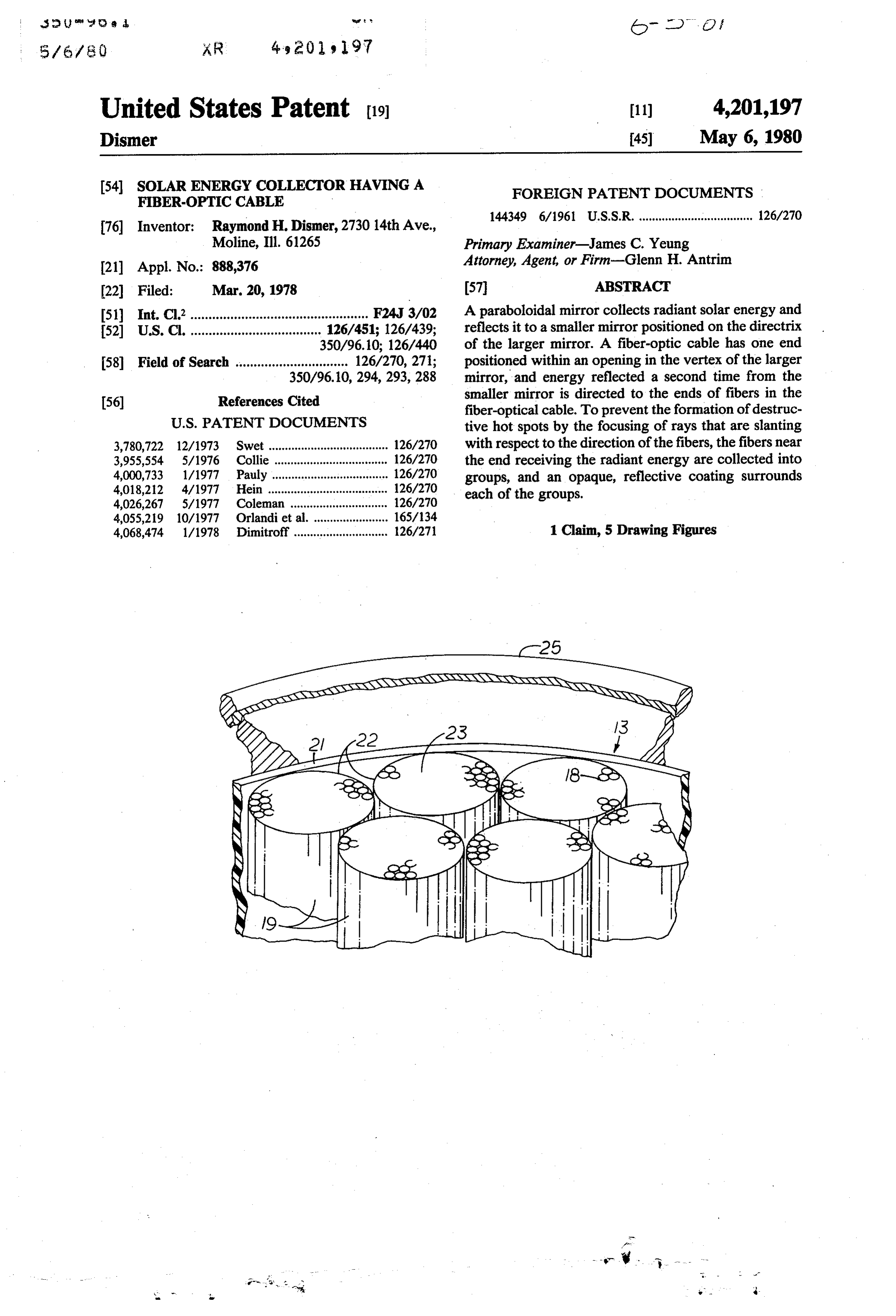
United States Patent (9. 11) 4,201,197 Dismer (45) May 6, 1980 (54). SOLAR ENERGY COLLECTOR HAVING A FOREIGN PATENT DOCUMENTS
FBER-OPTC CABLE
144349 6/1961 U.S.S.R. ................................... 126/270 76) Inventor: Raymond H. Dismer, 2730 14th Ave.,
Moline, Ill. 61265 Primary Examiner-James C. Yeung 21 Appl. No.: 888,376 Attorney, Agent, or Firm-Glenn H. Antrim 22 Filed: Mar. 20, 1978 57 ABSTRACT 51) Int. Cl’................................................. F24, 3/02 A paraboloidal mirror collects radiant solar energy and 52 U.S. C. .................................... 126/451; 126/439; reflects it to a smaller mirror positioned on the directrix 350/96.10; 126/440 of the larger mirror. A fiber-optic cable has one end 58) Field of Search ............................... 126/270,271; positioned within an opening in the vertex of the larger 350/96.10, 294, 293,288 mirror, and energy reflected a second time from the 56) References Cited smaller mirror is directed to the ends of fibers in the fiber-optical cable. To prevent the formation of destruc
3,780,722 12/1973 Swet ..................................... 126/270 with respect to the direction of the fibers, the fibers near 3,955,554 5/1976 Collie ... 126/270 the end receiving the radiant energy are collected into 4,000,733 1/1977 Pauly. ... 126/270 groups, and an opaque, reflective coating surrounds 4,018,212 4/1977 Hein ...... ... 126/270 each of the groups.
4,026,267 5/1977 Coleman ....... ... 126/270 4,055,219 10/1977 Orlandi et al. ... 165/134 4,068,474 1/1978 Dimitroff............................. 126/271 1 Claim, 5 Drawing Figures
Page 2
Drawing sheet — no readable text.
Page 3
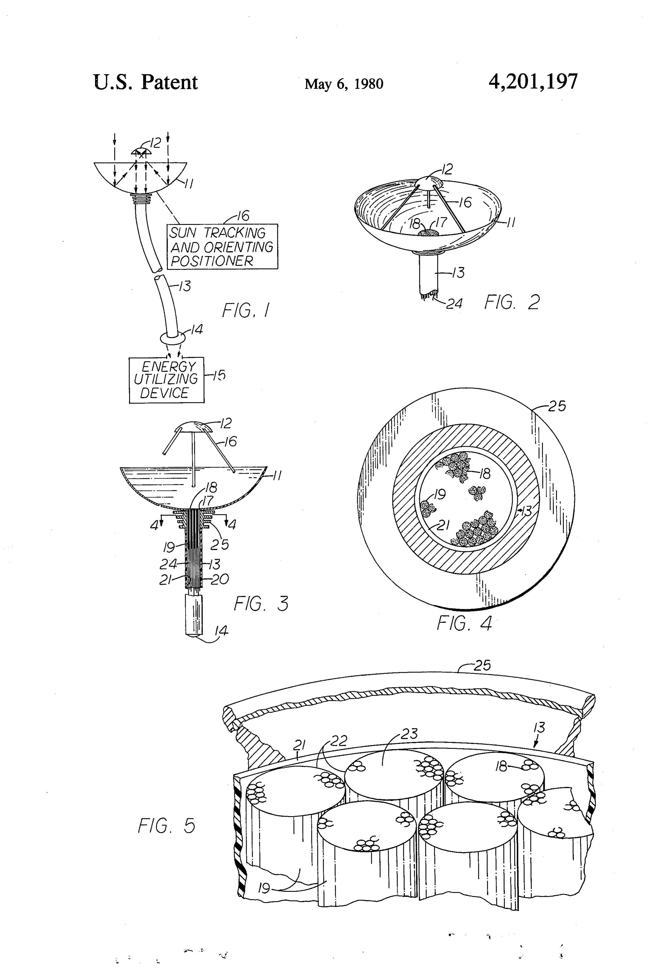
SOLAR ENERGY COLLECTOR HAVING A BRIEF DESCRIPTION OF THE DRAWING FBEROPTC CABLE FIG. 1 is a diagram of a solar heat collecting and transmitting system of this invention;
BACKGROUND OF THE INVENTION FIG. 2 is a top perspective view of two mirrors in the This invention relates to systems for collecting and heat collecting system;
transmitting solar energy and particularly to systems FIG. 3 is a longitudinal cross-sectional view of the having sets of two collecting mirrors and fiber-optic larger one of the two heat collecting mirrors and a cables. fiber-optic transmission cable connected to the mirror;
Many different arrangements have been proposed for cable and a radiatora cross-sectional view of the fiber-optic collecting solar energy from above the roofs of build 4-4 adjacent the larger mirror on lines ings and transmitting the energy mostly as heat to loca of FIG. 3; and tions within the buildings. A system described in U.S. ofFIG. the 5 is a magnified, fragmentary, perspective view upper end of the fiber-optic cable.
Pat. No. 4,026,267 issued to Rich F. Coleman on May 15 31, 1977 has groups of wide-angle lenses mounted on a DETAILED DESCRIPTION OF THE roofto focus radiant energy on upper ends offiber-optic PREFERRED EMBODIMENT cables. The lower ends of the fiber-optic cables termi The solar energy system of FIG. 1 comprises a col nate in heat sinks that supply heat to an enclosure. lector having a paraboloidal mirror 11 and an aspherical Rather than using lenses, mirrors may be used to con 20 mirror 12, a fiber-optic cable 13 for transmitting solar centrate solar energy. The use of multiple mirrors for energy over a moderate distance, and a focusing lens 14 concentrating solar heat and means for controlling the for concentrating energy on an energy utilizing device mirrors to track the sun are shown in U.S. Pat. No. 15. A sun tracking and orienting positioner 16 is me 3,905,352 issued to Arnold Jahn on Sept. 16, 1975. Heat chanically connected to the mirror 11 and operates concentrated from a system of mirrors may be applied 25 according to known methods to track the sun. The rays to a boiler connected to a device for utilizing energy. of the sun are reflected from the paraboloidal mirror 11 SUMMARY OF THE INVENTION to the mirror 12 that is preferably positioned on the directrix of the mirror 11. The mirror 12 is spaced from
A relatively large mirror or reflector and a small the mirror 11 such that its reflective surface coincides mirror have respective reflective surfaces that are 30 with the area over which the rays from the sun are spaced apart a fixed distance and face each other. The concentrated by the mirror 11.
radiant energy from the sun is collected by the larger To transmit energy that is collected by the mirror 11, mirror and directed over an area coincident with the the fiber-optic cable 13 has an end for an input con reflecting surface of the smaller mirror. A tracking nected at the vertex of the mirror 11. The cable 13 can device, such as those presently used for tracking the 35 be of moderate length for transmitting energy to a loca sun, is connected to the arrangement of mirrors to di tion where it can be conveniently used, usually at a rect the reflective surface of the larger mirror in the location that is lower than the location of the mirrors 11 direction of the sun. and 12. The mirror 12 has the proper shape for concen The center of the larger mirror has an aperture, and trating the energy received from the mirror 11 over an an end of a fiber-optic cable for an input is positioned in area that coincides with the area encompassing the ends the aperture so that the ends of fibers of the cable face of fibers at the input of the fiber-optical cable 13. The the smaller mirror or reflector. The smaller mirror di focusing lens 14 at the other end or output of the fiber rects the rays that have been focused on it by the larger optic cable 13 focuses the radiant energy received from mirror over an area coincident with the input of the the sun as much as required to provide the desired tem fiber-optic cable. The fibers of the cable have sufficient 45 perature at the energy utilizing device 15. diameter to transmit a wide spectrum of radiant energy. The amount of energy at the output of the system is An end of the fiber-optic cable for an output terminates dependent upon the size of the collecting mirror 11 and at a lens to focus energy on a utilizing device. If desired, the diameter of the cable 13 in addition to the focusing a pair of adjustable polarized disks can be inserted be power of the lens 14. The heat can be concentrated for tween the end of the cable and the focusing lens to 50 operating thermal generators or for melting material control the amount of heat that is applied to the utilizing such as steel, or less concentrated for heating water. device. The system could be especially applicable in outer space The larger mirror is preferably paraboloidal, and its to provide a continuous source of energy when applied aperture for receiving the end of the fiber-optic cable to thermal generators or to other generators. The lens for the input is located at the vertex of the mirror. The 55 14 is preferably a plano-convex lens integrated within smaller mirror has a concave face shaped as required to the end of the fiber-optic cable 13 with the plane portion focus radiant energy over an area coincident with the in contact with the ends of the fibers 24. end of the fiber-optic cable. In order to prevent the end According to FIG. 2, the smaller mirror 12 is sup of the cable at the input from becoming destructively ported by members 16 such that the reflective faces of hot, a metallic heat radiator having fins surrounds the 60 the mirrors 11 and 12 are facing each other. Groups of end of the fiber-optic cable, and substantial focusing of small mirrors having either plane or curved faces as heat waves is prevented in the input of the cable. The required might be used in place of the mirrors 11 and 12 fibers at the input of the cable are separated into groups, providing the mirrors direct energy over areas corre and each group of fibers is surrounded by an opaque, sponding to the area of the mirror 12 and the area of the reflective coating. The coating prevents rays from trav 65 end of the cable 13 respectively. When a paraboloidal eling in a slanting direction through the walls of the mirror 11 is used, it has through its vertex an aperture fibers and focusing energy at points within the end of having a diameter about equal to the diameter of the the cable. cable 13. The cable 13 is attached to the mirror 11 to
Page 4
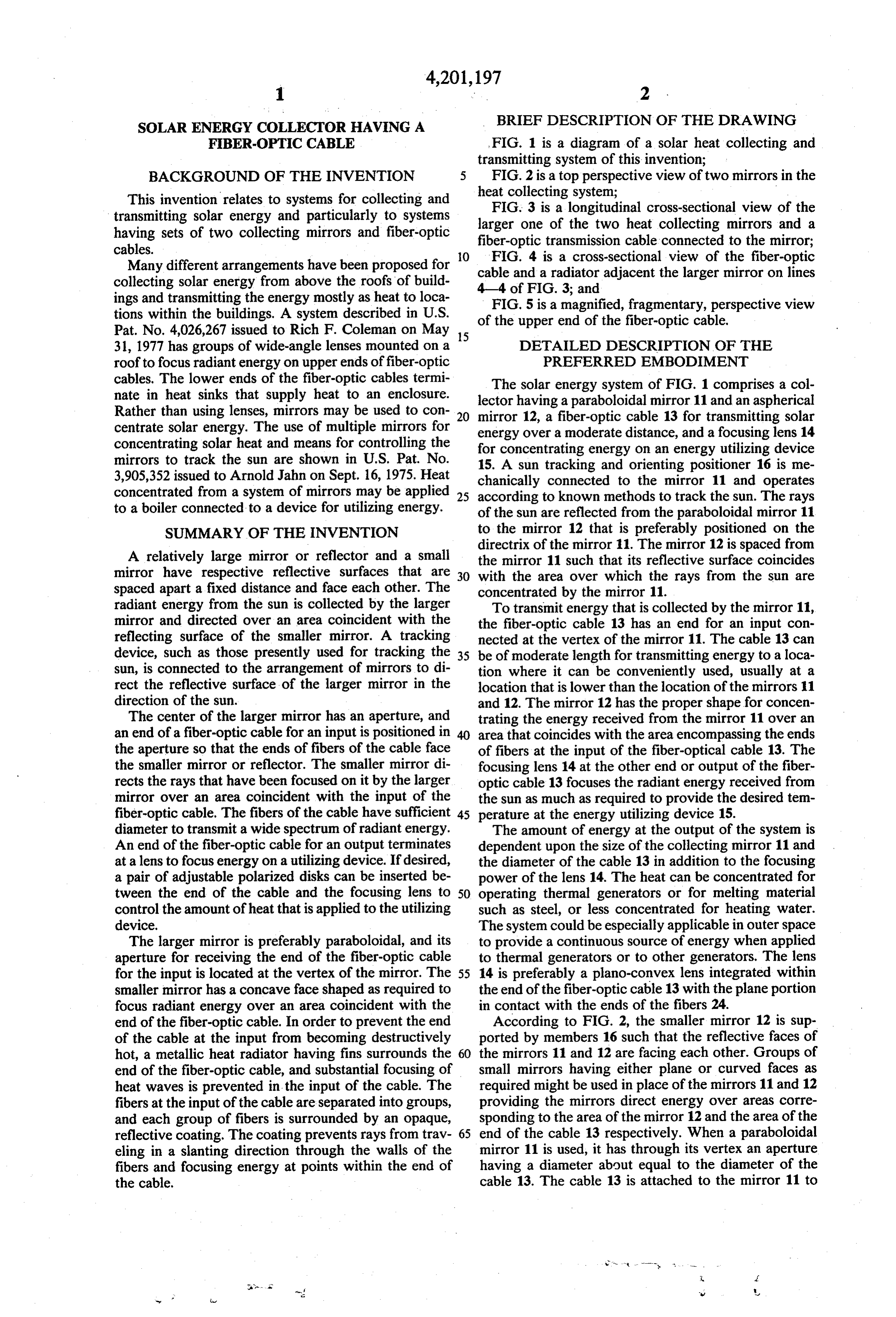
expose ends of fibers 18 to the rays directed by the said collector having first and second concave reflec mirror 12. To avoid destructive heat from the focusing tors, said second reflector being substantially of rays that are not parallel to the fibers 24, the adjacent smaller than said first reflector, each of said reflec fibers are arranged into groups that constitute bundles tors having a front reflecting surface, 19. means for rigidly supporting said second reflector at As shown in FIGS. 3 and 4, the fiber-optic cable 13 a predetermined distance in front of said first re has a flexible, plastic cover 20 having an inner reflective flector, said reflecting surfaces facing each other, surface 21. Within the covering, the fibers 24 are ar control means connected to said first reflector, said ranged into bundles 19 having the ends 18 of the fibers control means being operable to track the sun and exposed about even with the inner surface of the mirror 10 to turn said reflecting surface of said first reflector 11. In the magnified view of FIG. 5, the fibers having toward the sun, said first reflector being paraboloi the ends 18 are shown arranged into the bundles 19, dal for concentrating radiant solar energy over a each bundle being surrounded by an opaque coating 22. wave front coinciding with said reflecting surface In order to contain the energy within the cable 13, each of said second reflector, of the coatings 22 has an inner reflective surface 23. The 5 said fiber-optic cable being connected to said collec heat that is still produced within the input end of the tor by having a first end of said cable for input of cable 13, is dissipated to a large extent by a radiator 25 radiant energy positioned through an opening in about the cable 13 adjacent the vertex of the mirror 11. said first reflector to expose said first end to energy The radiator 25 has a heat-conductive, cylindrical inner reflected from said reflecting surface of said second surface that fits in close thermal contact with the reflec 20 reflector, said second reflector being concave for tive coatings 21 and 22 about the fibers 24 of the cable concentrating radiant solar energy over a wave 13, and a plurality of peripheral, spaced, conductive fins front coinciding with said first end, that extend radially from the cylindrical portion of the lens positioned to receive energy from a second end radiator 25. of said fiber-optic cable at a distance from said In order to apply through lens 14 of FIG. 1 heat to 25 input for concentrating solar energy transmitted the device 15 in an amount less than the maximum through said fiber-optic cable on an energy utiliz amount available, a pair of polarizing disks may be ing device, and mounted at the output between the end of the cable 13 wherein said fiber-optic cable has a plurality of fibers and the focusing lens 14. When a large quantity of heat of sufficient diameter to transmit infra-red rays of is to be controlled, cooling means will need to be pro 30 solar energy substantially independent modes, said vided to cool the polarizing disks. fibers being divided into groups over a substan I claim: tially length at said first end of said fiber-optic 1. A solar energy concentrating system comprising: cable, and an opaque inwardly reflective coating a collector of radiant energy, a fiber optic cable con surrounding each of said groups.
Provenance
- Collection
- Cited prior art
- Original PDF
- patentimages.storage.googleapis.com →
- Filed
- 1978-03-20
- Pages
- 4
- Method
- pdftotext (the PDF's own text layer) + pdftoppm 300dpi page scans
- Source
- Google Patents bibliographic record
- Granted
- 1980-05-06
- Inventors
- Raymond H. Dismer
- Transcribed from
- patentimages.storage.googleapis.com →