patent · US5375043
Lighting unit
20 December 1994
Page 1 — bibliographic record
United States Patent (19) 11 Patent Number: 5,375,043 Tokunaga 45) Date of Patent: Dec. 20, 1994 54) LIGHTING UNIT FOREIGN PATENT DOCUMENTS 75) Inventor: Makoto Tokunaga, Tokyo, Japan 1-252933 10/1989 Japan. 73) Assignee: Inoue Denki Co., Inc., Tokyo, Japan Primary Examiner-Richard R. Cole 21) Appl. No.: 87,640 Attorney, Agent, or Firm-Jordan and Hamburg
Disclosed is a lighting unit of an indirect type, capable (30) Foreign Application Priority Data of varying the luminance and color of illumination with Jul. 27, 1992 JP Japan .................................. 4-218815 respect to a target to be lit thereby ensuring an effective display of the target, and further capable of using itself 51 int. Cli................................................ F21W 8/00 as a display unit. The lighting unit comprises a light 52 U.S.C. ........................................ 362/31; 362/32; guide plate having one side fashioned into an uneven 362/231; 362/235; 362/800 surface or a reflective surface; a plurality of light emit 58 Field of Search ................... 362/31, 32, 227, 231, ting diodes for supplying a light to the light guide plate, 362/235, 249, 800; 40/448, 442, 452 the light derived from the diodes being dispersed
through the light guide plate; and a control section which controls actions including blinking of the light
4,975,809 12/1990 Ku ......................................... 362/31 to emit a light different in color from that of the others 5,079,675 1/1992 Nakayama. so that the color or blinking of illumination can be arbi 5,124,890 6/1992 Choi et al. ............................ 362/31 trarily varied through the control by means of the con 5,136,483 8/1992 Schöniger et al. ... 362/61 trol section.
5,147,129 9/1992 Ku .................. ... 362/31 5,239,450 8/1993 Wall ...................................... 362/31 12 Claims, 3 Drawing Sheets
Page 2
Drawing sheet — no readable text.
Page 3
Drawing sheet — no readable text.
Page 4
Drawing sheet — no readable text.
Page 5
LIGHTING UNIT BRIEF DESCRIPTION OF THE DRAWINGS
The object and advantages of the present invention
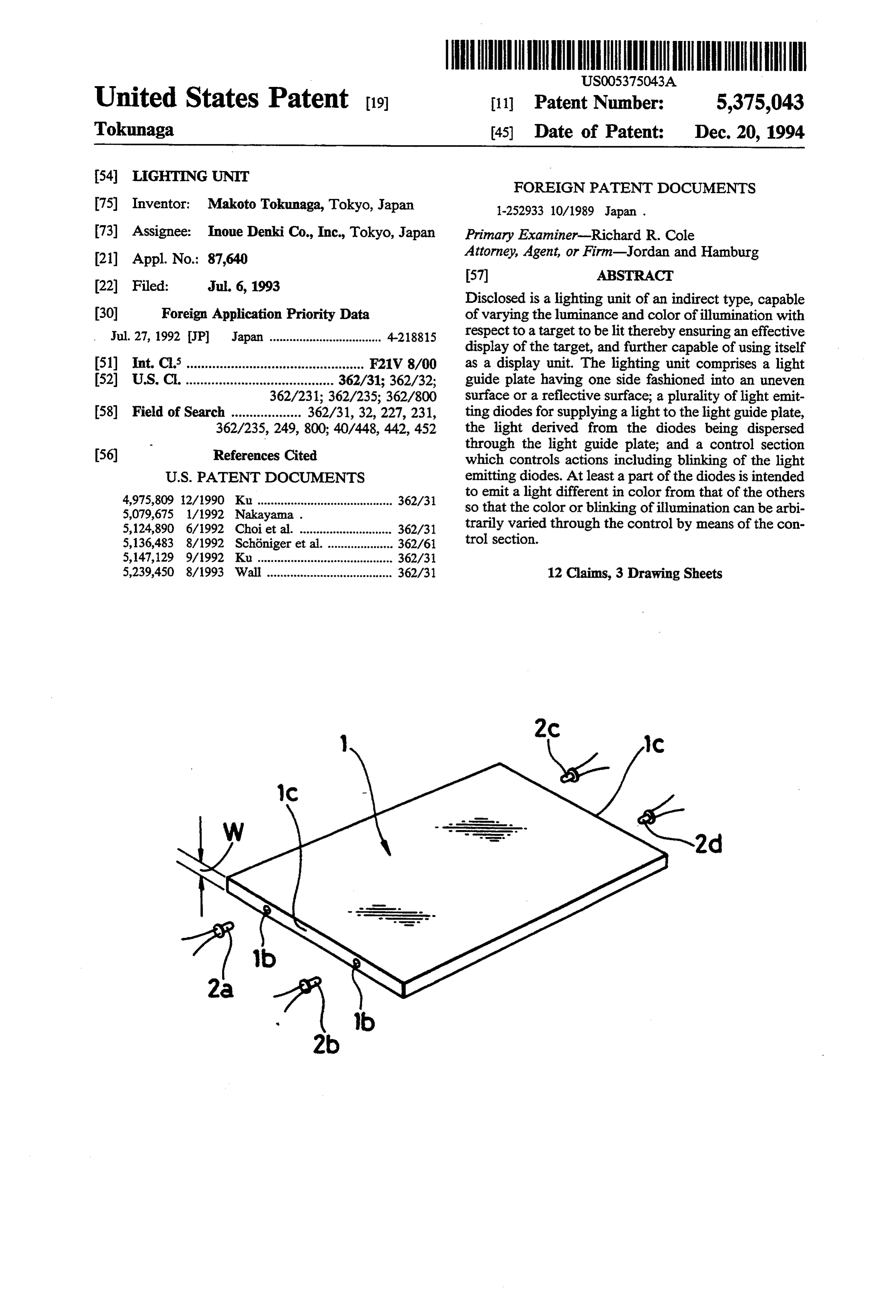
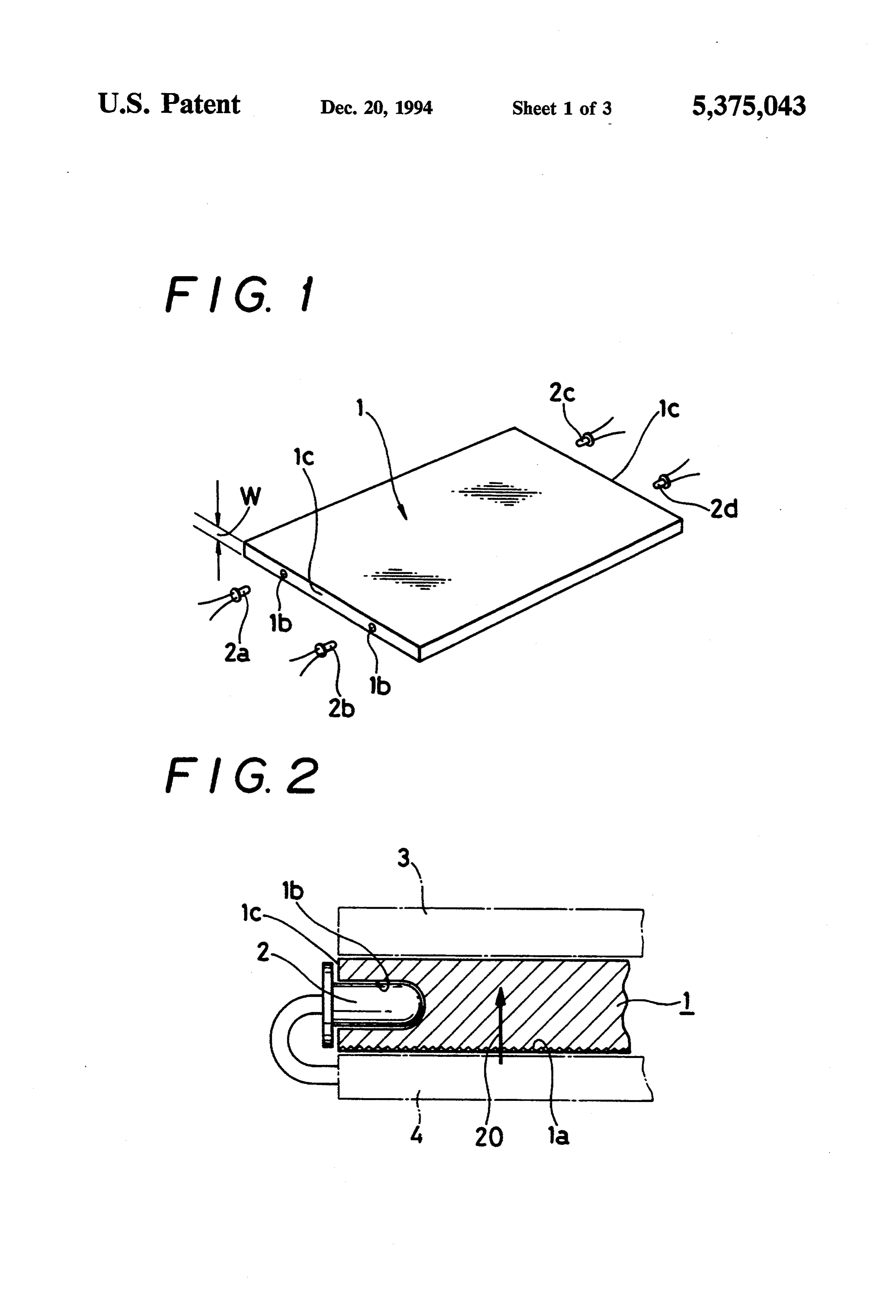
BACKGROUND OF THE INVENTION will become more apparent, when viewed in conjunc 1. Field of the Invention tion with the accompanying drawings, in which; The present invention generally relates to a lighting FIG. 1 is a perspective view of a light guide plate unit, and more particularly to a lighting unit having showing an embodiment of the present invention; light emitting diodes as light sources giving off lights to FIG. 2 is a partial sectional view of the light guide be dispersely reflected to illuminate a target, and also 10 plate
FIG.
receiving light emitting diodes;
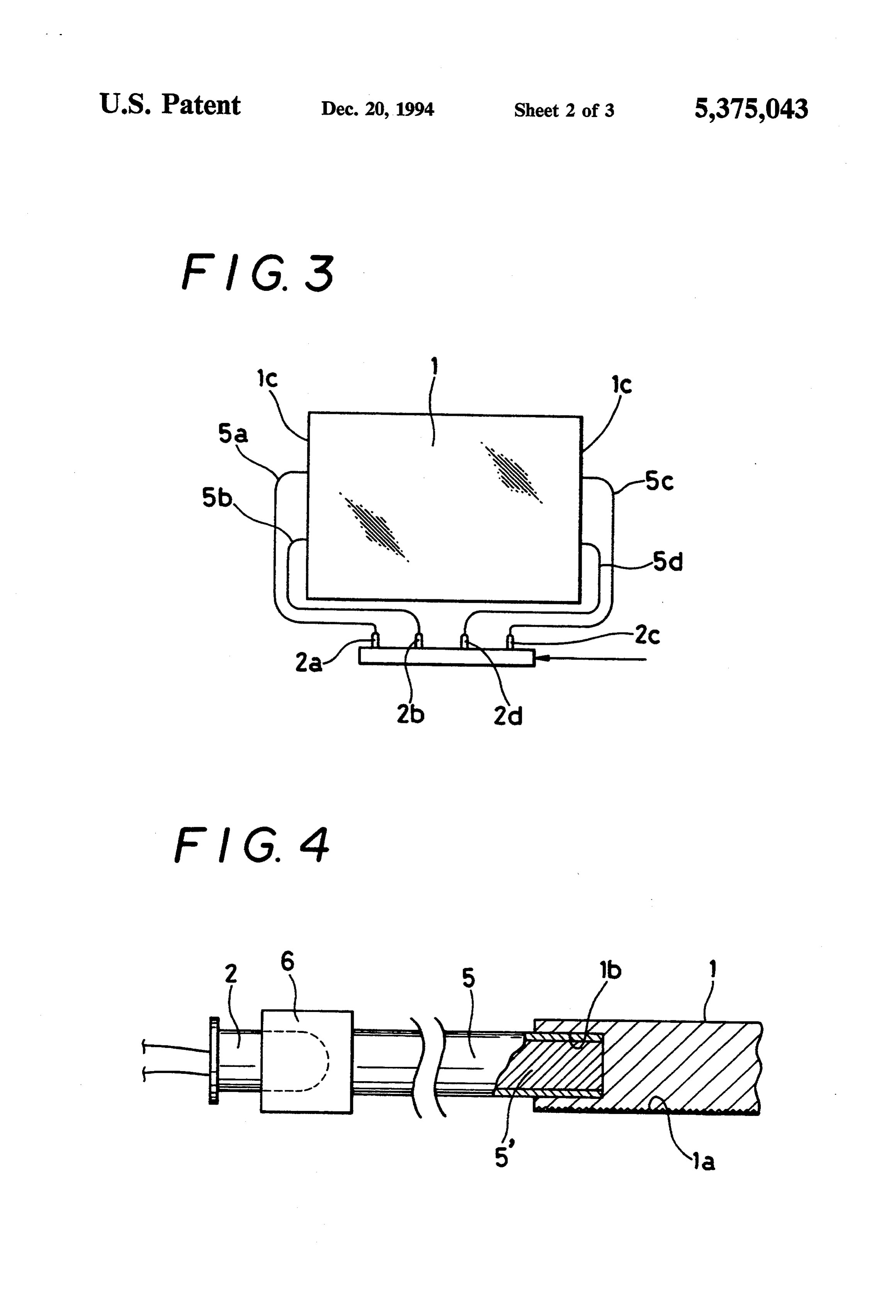
3 is a top plan view of the light guide plate capable of using itself as a display unit. showing another embodiment of the present invention; 2. Description of the Related Arts FIG. 4 is a partial sectional view showing the connec Up until now, there have been proposed a variety of tion of optical fibers:
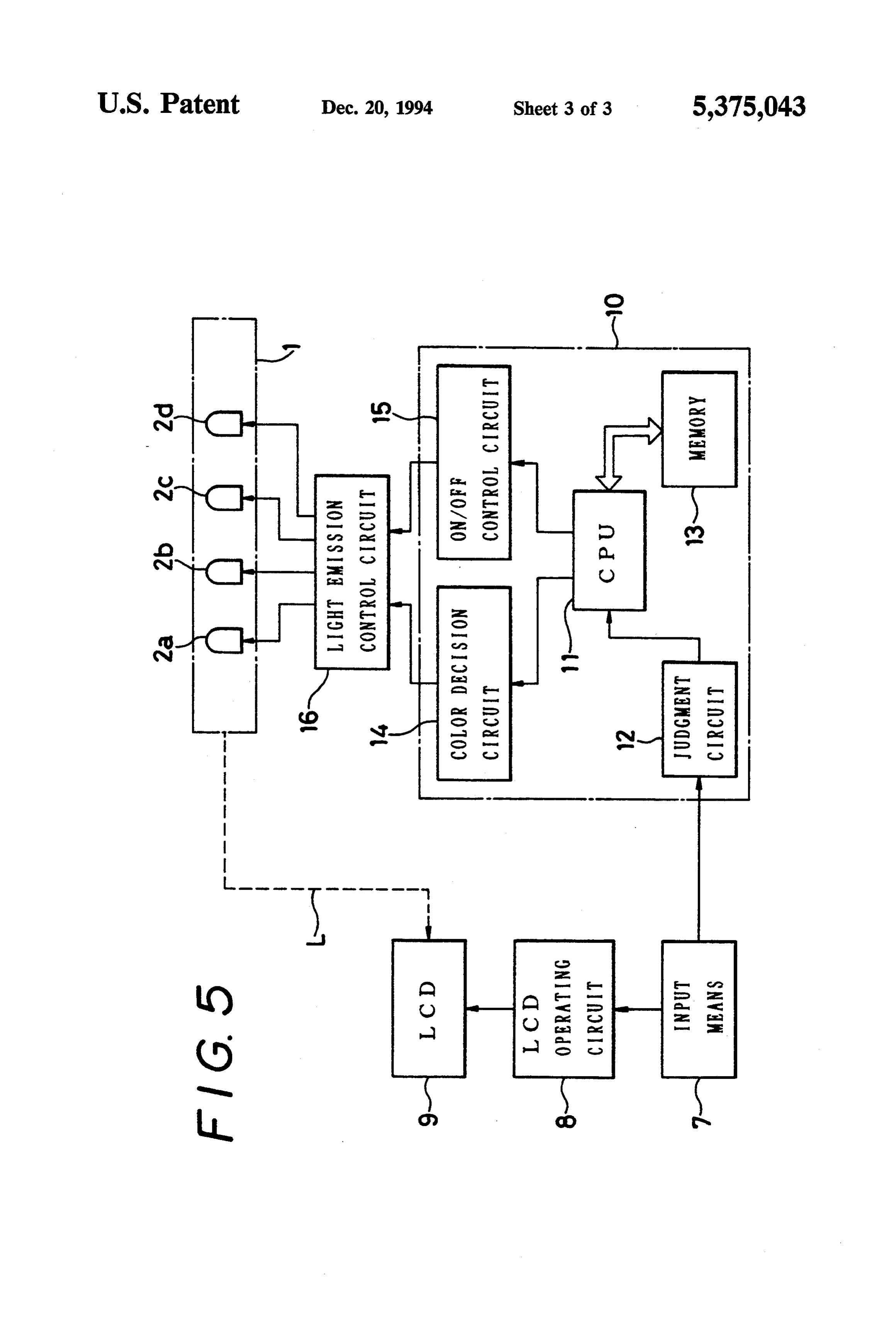
indirect-type light units which comprise a transparent plate having one side fashioned into an uneven surface 15 mechanism of a block
portable diagram representing a lighting game machine incorporating a or a reflective layer so as to serve as a planar light emit lighting unit in accordance with the present invention. ting member, and a plurality of light sources disposed on the side edges of the transparent plate and giving off DESCRIPTION OF THE PREFERRED lights to be scattered by the uneven surface or the re EMBODIMENTS flective layer to substantially uniformly illuminate the 20 Referring first to FIGS. 1 and 2, there are shown entire transparent plate. generally a light guide plate 1 in accordance with the Such type of lighting units typically include a rela present invention, and partially the light guide plate tively large and powerful light sources such as a fluores loaded with light emitting diodes 2 described later, cent lamp or a tungsten halogen lamp arranged on the respectively. The light guide plate 1 is essentially a side edges of the transparent plate. For example, large 25 transparent plate made of a transparent material such as scale ones are used as a device for lighting interior acrylic resin or glass. The transparent plate 1 includes at walls, while small-scale ones are utilized as a back light its one side (at its reverse side in FIG. 1) a reflective or a device for lighting a liquid crystal display surface surface 1a (refer to FIG. 2) having thereon a multiplic on a small-sized computer or a word processor. ity of grooves in series or a multiplicity of minute reces Such lighting units that are suitable for relatively 30 ses in a dispersed manner. It is to be appreciated that the uniformly illuminating a relatively large area have a reflective surface 1a may comprise a reflective layer tendency toward technical development to ensure, for formed by printing or other method, instead of such example, more uniform overall lighting, enlargement in uneven surface. Also, the transparent plate making up lighting area, or increased illuminance. the light guide plate is not exactly limited to uncolored A small-sized device having a display surface such as 35 one, and any particular color having light transmission a pocket calculator, a portable telephone set, or a porta properties may be imparted to the plate. ble game machine often uses a liquid crystal as its dis The light guide plate 1 is shown having relatively play surface. In this case, the conventional lighting unit compact dimensions, for example, of several cm in is unsuitable to the above products having batteries as able length and width with several mm in thickness W, suit their power sources due to its large amount of power for use as a backlight for a liquid crystal display consumption. Therefore, most of the products do not (LCD) guide panel on a portable electronic device. The light plate 1 includes a pair of confronting side edges 1c employ such lighting unit.
each having a couple of small holes 1b intended to re
SUMMARY OF THE INVENTION ceive light emitting diodes 2a to 2d (hereinafter referred It is therefore the object of the present invention to 45 to ItasisLED's),
respectively, serving as light sources.
noted that at least a part of the LED's 2a to provide a lighting unit having a reduced size, and capa 2d to be loaded into the light guide plate 1 must emit a ble of not only functioning as a mere lighting unit but light also varying the luminance and color of illumination example, the LED's 2afrom different in color that of the remainder. For with respect to a target to be lit thereby ensuring an 50 while the LED's 2b andand 2d may emit a light in red, 2c may emit a light in green.
effective display of the target, and further capable of Alternatively, all of the four LED’s may send out dif using itself as a display unit. ferent colors.
According to one aspect of the present invention, in Presently, there have been a variety of LED's on the order to accomplish the above object there is provided market.
a lighting unit of an indirect type, comprising a light 55 arsenide For instance, the LED composed of gallium (GaAs) or gallium aluminum arsenide guide plate comprised of a small-sized uncolored or (GaAlAs) emits a red light, the one composed of gal colored transparent plate having one side fashioned into lium phosphide (Gap) emits ared or greenlight, the one an uneven surface or a reflective layer; a plurality of composed of gallium arsenide phosphide (GaAsP) emits light emitting diodes each serving as a light source for a red, yellow or orange light, and the one composed of supplying a light to the light guide plate, the light de 60 gallium nitride (GaN) or silicon carbide (SiC) emits a rived from the light source being dispersed through the blue light. Therefore, prior to mounting onto the light light guide plate; and a control section which controls guide plate, the LED's 2a to 2d can be appropriately actions including blinking of the plurality of light emit selected in view of the color at the time of emission of ting diodes; at least a part of the plurality of light emit light.
ting diodes being intended to emit a light different in 65 FIG. 2 exemplarily illustrates a state where the color from that of the others so that the color or blink LED's are loaded into the light guide plate 1. A liquid ing of illumination can be arbitrarily varied through the crystal display panel designated at reference numeral 3 control by means of the control section. is disposed on top of the light guide plate 1 so as to
Page 6
allow the content of the liquid crystal display to be Denoted by reference numeral 10 is a means of con irradiated with a light sent forth from the light guide trolling the illumination of the lighting unit, more spe plate 1. Under the light guide plate 1 there is placed an cifically, a means of controlling the action of the LED's electronic substrate (or printed wiring board) 4 for serving as light sources of the lighting unit, which in operating the liquid crystal display panel. The LED's cludes a central processing unit (CPU) 11, a judgment 2a to 2d are electrically connected to the substrate 4 so circuit 12, a memory 13, a color decision circuit 14, and that they can be turned on or off in response to the an on/off control circuit 15. The LED's 2a to 2d are operation of the liquid crystal. Naturally, the arrange connected to the control means 10 by way of a light ment of the LED's is not limited to the one shown in emission control circuit 16. FIG. 1, and they may be arranged on the other side 10 The content of the game appears on the liquid crystal edges of the light guide plate 1. display 9 in response to an input operation performed Referring next to FIGS. 3 and 4, there is shown a through the input means 7 by the game machine opera second embodiment of the present invention, in which tor in compliance with a game rule. Then, the judgment the LED's 2a to 2d serving as light sources are indi 15 circuit 12 in the control means 10 judges whether the rectly associated with a pair of confronting side edges input operation conforms to the game rule or whetherit of the light guide plate 1 by way of optical transmission is advantageous to the game player. Lighting patterns media, differently from the above embodiment having individually corresponding to the judgment results are the LED's directly fitted to the side edges of the light previously created and stored within the memory 13. guide plate 1. The optical transmission media comprises 20 The central processing unit 11 retrieves a lighting optical fibers 5a to 5d whose one ends are fitted into the pattern corresponding to a result of judgment from the small holes 1b provided in the pair of confronting side memory 13, and for the execution of the lighting pattern edges 1c in the same manner as shown in the first em issues an14operation signal to either the color decision bodiment (refer to FIG. 4). On the contrary, the LED's circuit or the on/off control circuit 15, or alterna tively to both the color decision circuit 14 and the on/- 2a to 2d are positioned apart from the light guide plate 25 off 1, and connected to the other ends of the optical fibers the controlon-off circuit 15. The color decision circuit 14 and control circuit 15 are intended to issue a 5a to 5d, respectively. Although the LED's 2a to 2d serving as the light sources are arranged in the vicinity signal acting as a light-on or light-off signal for the LED's to the light emission control circuit 16 so that of and in the same plane as the light guide plate 1 in the
FIG.3, they may be arbitrarily positioned, for example, 30 withLED's the 2a to 2d are turned on or off in conformity signal. The liquid crystal display 9 is thus illu under the light guide plate 1. It is also conceivable to minated by a light L derived from the lighting unit. use, for example, several tens of LED's or for a large More specifically, let the content of the game to be sized light guide plate a multiplicity of, that is, several performed in the game machine be "the operator who hundreds of LED's. In this case, the use of the optical has a certain number of points is to recover treasures fibers increases the freedom in designing an apparatus 35 taken by the enemy”. If the number of points possessed incorporating the present lighting unit, for example, by by the operator is decreased, then the red LED may be disposing the multiplicity of LED's and a control for turned on to redden the screen of the liquid crystal the LED's separately from the light guide plate. display 9, and if the danger is further increased, then the FIG. 4 exemplarily shows connections of an optical on/off control circuit 15 may be actuated to allow an fiber 5, which has one end fitted into the small hole 1b intermittent flash of red light. On the contrary, provided in the side wall of the light guide plate 1 and number of points is increased or the treasures areifsuc the the other end linked with the LED 2 through a connec cessfully recovered, the lighting may be greened. More tor 6. This connection ensures that the light guide plate over, providing that red, yellow, green, and blue are receives a light emitted from the LED 2 by way of a assigned to the lights the LED's 2a to 2d emit, respec core 5' of the optical fiber 5 and gives off light. 45 tively, a white light can be obtained by simultaneously Although the LED's serving as light sources are all giving off the red, green, and blue lights since they are associated with the side edges of the light guide plate so-called three primary colors, thus enabling an ordi directly or indirectly via the optical fibers 5 in the above nary non-colored lighting. In addition, the simultaneous embodiments, the LED's or at least a part of the other lighting of yellow and red LED's can present a tone of ends of the optical fibers connected with the LED's SO color substantially equal to gold, which is suitable for may be arranged at predetermined positions on the light the display indicating, for instance, that the game was guide plate 1 in the direction of its thickness (as indi over with a high points.
cated by an arrow 20 in FIG. 2). In the case where the LED's are disposed not only in Referring finally to FIG. 5, there is shown a block the side edges of the light guide plate but also in the diagram of a configuration, by way of example, in 55 direction of thickness thereof, a basic lighting for the which the lighting unit described above is utilized as a light guide plate may be allotted to the LED's in the device for illuminating the liquid crystal display (LCD) side edges, while the provision of contrast to the screen on a portable electronic game machine such as "GAME of the liquid crystal display may be allotted to the BOY (trade mark). LED's extending in the direction of thickness and ap The game machine comprises an input means 7 in propriately blinking, thereby ensuring a wide variety of cluding keys and button switches; an LCD operation display.
circuit 8 for operating liquid crystal display based on Although the above description has been made on, by data supplied through the input means 7; and a liquid way of example, the application of the present lighting crystal display (LCD) 9 to be operated in accordance unit to the game machine, it will be obvious to those with image signals output from the LCD operation 65 skilled in the art that the present lighting unit has vari circuit 8. This lighting unit is incorporated into the ous other applications to, for example, display surfaces game machine so as to illuminate the liquid crystal dis of a speedometer for motor vehicles as well as measur play 9. ing instruments such as a sound level meter, a bathome
Page 7
ter, and a sphygmomanometer. For example, the appli a plurality of light emitting diodes each serving as a cation to the speedometer would allow the color of a light source and being arranged to supply light to display light for the speedometer to change from blue said light guide plate, said light emitting diodes which has been lit so far to red if the vehicle speed including light emitting diodes of different colors; exceeds a legal speed limit. Furthermore, the applica and tion to the liquid crystal display indicating a measure a control section connected to energize said plurality ment value of the sound level meter would allow the of light emitting diodes; illumination for the liquid crystal display to be green if said control section comprising means for selectively the measurement value is not more than the preset 10 energizing said liquid crystal display panel and sound level, and to become red if it is over the preset means for selectively energizing said light emitting value. diodes to control the color of illumination of said What is claimed is: lighting unit in dependence upon said selective 1. A lighting unit of an indirect type for substantially energization of said liquid crystal display panel. uniform illumination, comprising: 6. The lighting unit of claim 5 wherein said lighting a light guide plate comprised of a transparent plate; 15 unit tal is positioned adjacent a first side of said liquid crys display panel.
a plurality of light emitting diodes each serving as a light source for supplying a light to said light guide unit is sandwichedunit 7. The lighting of claim 5 wherein said lighting between said liquid crystal display plate, said light emitting diodes being arranged to panel and said control section.
enable selective illumination of different colored 20 8. In a display system of the type having a liquid light by said lighting unit;
means for substantially uniformly distributing said control the selective energization circuit crystal display panel, a control connected to of said liquid crystal light in said light guide plate; and display panel, and a lighting unit for supplying light to a control section connected to energize said plurality said liquid crystal display panel, the improvement of light emitting diodes; 25 wherein said lighting unit comprises: said control section comprising a liquid crystal dis a light guide plate comprised of a transparent plate; play panel operating system adapted to output a plurality of light emitting diodes each serving as a control signals for a liquid crystal display panel, light source and being arranged to supply light to and means for energizing said light emitting diodes said light guide plate, said light emitting diodes in response to outputs of said liquid crystal display 30 including light emitting diodes of different colors; panel operating system, whereby the illumination and of said lighting unit varies as a function of said a control section connected to energize said plurality output control signals. of light emitting diodes;
2. The lighting unit of claim 1 wherein said means for said control section comprising means responsive to substantially uniformly distributing said light comprises 35 said control circuit for illuminating said lighting a reflective layer covering one surface of said light unit with different colors in response to informa guide plate. tion displayed on said liquid crystal display panel. 3. The lighting unit of claim 1 wherein said means for 9. The display system of claim 8 wherein said liquid substantially uniformly distributing said light comprises 40 crystal display panel has a viewing surface and a rear grooves or recesses distributed throughout one surface said surface, and said light guide plate is positioned adjacent of said light guide plate. rear surface.
4. The lighting unit of claim 1 wherein said control guide The10. display system of claim 8 wherein said light section comprises means for energizing said light emit display panelisand plate sandwiched between said liquid crystal ting diodes to provide a blinking illumination from said 45 11. The display said control section. system of claim 10 comprising a re light guide plate. flective surface on the side of said light guide plate 5. A lighting unit for illuminating a liquid crystal opposite said liquid crystal display panel for substan display device of the type having a liquid crystal display tially uniformly distributing said light. panel and a control circuit connected to control the 12. The display system of claim 10 comprising a re selective energization of said liquid crystal display 50 cessed or grooved surface on the side of said light guide panel, the improvement wherein said lighting unit com plate opposite said liquid crystal display panel for sub prises: stantially uniformly distributing said light. a light guide plate comprised of a transparent plate; k : k k
Provenance
- Collection
- Cited prior art
- Original PDF
- patentimages.storage.googleapis.com →
- Filed
- 1993-07-06
- Pages
- 7
- Method
- pdftotext (the PDF's own text layer) + pdftoppm 300dpi page scans
- Source
- Google Patents bibliographic record
- Granted
- 1994-12-20
- Inventors
- Makoto Tokunaga; Inoue Denki Co Inc
- Transcribed from
- patentimages.storage.googleapis.com →