patent · US4943125A
Solar collector
24 July 1990
Page 1 — bibliographic record
United States Patent (19) 11) Patent Number: 4,943,125 Laundre' et al. 45 Date of Patent: Jul. 24, 1990 54 SOLAR COLLECTOR 4,425,905 1/1984 Mori............................... 350/96.1 X 4,461,278 7/1984 Mori............................... 350/96.1 X 76) Inventors: John W. Laundre', 2865 Janet, 4,723,826 2/1988 Whitaker ............................ 350/96.1 Pocatello, Id. 83201; Timothy D. 4,798,444 A1989 McLean ........................... 350/96.24 Reynolds, 190N 680 W, Blackfoot,
Id. 83221; Mary B. Reynolds, 11372 Primary Examiner-Frank Gonzalez
W. Whispering Cliffs Dr., Assistant Examiner-John Ngo
Chubbuck, d. 83202 Attorney, Agent, or Firm-Richard C. Litman 21) Appl. No.: 301,877 57 ABSTRACT 22 Filed: Jan. 26, 1989 The following invention discloses a solar collector for 51 Int. Cl................................................ G02B 6/OO the collection and distribution of incident electromag (52) U.S. C. ................................ 350/96.1; 350/96.18: netic radiation. It is a collector which utilizes optic 350/96.24 fibers as the direct means for solar energy concentration 58 Field of Search ................. 350/96.1, 96.18, 96.23, and collection. The collector is of a hemispherical de 350/96.2, 96.24; 126/417, 451; 159/903 sign, or a variation thereof, allowing for the even col lection of sunlight regardless of the sun's position rela 56 References Cited tive to the horizon. Furthermore, the collector is of
4,201,197 5/1980 Dismer ........................... 350/96.1 X These features provide for a device that requires little 4,275,950 6/1981 Meyer ..... ... 350/96.1 maintenance and allows for high functionality. 4,389,085 6/1983 Mori ........ ... 350/96.
4,411,490 10/1983 Daniel .............................. 350/96.18 8 Claims, 2 Drawing Sheets
Page 2
Drawing sheet — no readable text.
Page 3
Drawing sheet — no readable text.
Page 4
The panels are usually designed as large flat plates to
SOLAR COLLECTOR maximize the collection area exposed to solar radiation. Maximum exposure is attained when the panels are
BACKGROUND OF THE INVENTION perpendicular to the rays of the sun. Moreover, to as 1. FIELD OF THE INVENTION sure a constanct exposure, the normal to these plates or This invention relates generally to the field of solar panels must be aligned toward the sun continually. collectors, and more particularly to the collection and As is well known, the sun has two primary motions. distribution of incident electromagnetic radiation utiliz During the day, the sun moves from east to west. Sea ing optic fibers as the direct means for solar engergy O sonally, the sun moves from north to south, its degree of concentration and collection. variation dependent upon the observer's geographic The art of collecting solar energy is a rapidly grow latitude. To account for this variation, a tracking system ing field. It began in response to the need for an inex must be utilized. This insures that the panel absorbs the pensive alternative to fossil and nuclear fuels. More maximum solar energy possible. Such a tracking system, over, there arises an additional advantage to the use of because of the fine control needed, can be both compli solar energy. The use of solar technology is considered 5 cated and expensive.
to be a non-polluting form of energy production as The second form of solar collection involves the compared to the two fuels mentioned. As a result of conversion of direct sunlight into the infrared portion of these advantages, the development of solar energy pro the electromagnetic spectrum. In this embodiment of duction has been ardently pursued. the art, heat is used to warm water or some equally However, the usefulness of solar energy as an eco 20 useful transport medium. This heated fluid is then piped nomically feasible alternative has yet to be proven. The to the interior of a home or building where the thermal current designs for solar collectors involve costly mate rials, tracking devices, and support equipment. This is energy is used for heating. However, this type of solar collection is subject to the same problems as the solar true whether the design involves a solar cell arrange cell variety; high costs, tracking systems, and a planar ment or a water heating design, both of which consti 25 tute the majority of current technology. Presently, the design.
this
These factors limit the economic usefulness of application as well.
large capital investment required for a solar collector design as compared with the eventual returns is prohibi arranged in a planarpiping
Generally, the for such a heating system is fashion in much the same fashion as tive. The factors that comprise this prohibition involve the cell variety. Such a design contains the same fallacy costly designs, control systems, and tracking systems. 30
There are two basic avenues the solar development as the solar cell design; large amounts of land are industry has traditionally followed. The first and per needed for arequires sizable application. Additionally, the initial haps most widely known of these avenues is the field of investment ing and piping the purchase of complicated valv systems. Also, a tracking system of requi
Solar cell technology. Solar cells are devices for the collection of incident sunlight wherein this sunlight is 35 site complexity must be used to assure maximum ther converted directly into electricity. The second of these mal output. The combination of these investments con two designs involves the heating of a transport medium stitutes the large capital expenditure associated with the or fluid by infrared radiation, a specific segment of the "hot water” design.
electromagnetic spectrum. From all aspects of this design, there exist a multitude When dealing with the solar cell design, in order to 40 of problems. The water heating system is subject to collect the most sunlight possible, these cells are almost weather conditions. The fluid medium is subject to always arranged in a panel fashion. A panel consists of freezing and boiling, both of which may damage the an assemblage of parts arranged in such a way as to piping. The piping system is further subject to corrosion form a flat, planar structure. Panels of these solar cells both from within the pipes and from without. As afore are further connected to one another to produce the 45 mentioned, these problems are further complicated by energy requirements of the application. This arrange the need for the same type of tracking system as associ ment is prohibitive. Individual solar cells are very ex ated with the solar cell design.
pensive, and in order to produce a sizable amount of Both of the aforementioned systems for the collection electricity by these cells, literally thousands of them and use of solar energy require still another additional must be connected together. Not only is such an ar 50 feature which makes their feasibility for many applica rangement expensive, but large applications can con tion costly. In both cases, the devices must be used in sume vast quantities of acreage such that one may ob situ, and this means that the conversion of solar energy tain maximum benefits. to a more useful form must occur at the collection point. There exists an additional problem when the panels in In order to achieve this end, the solar devices must be which these cells are arranged are exposed to environ 55 mountd on a roofing structure of a home or building or ment conditions. Solar cells are particularly susceptible its equivalent. As a result, the supportig trusses of these to the effects of varying temperatures and varying hu roofing structures must be reinforced to accommodate midity. Wear on the cells is accelerated by adverse the additional weight. The cost of such reinforcement weather conditions. This wear necessitates the need for adds to the overall expenditure of the application. Con continual replacement and maintenance. To achieve the 60 sequently, the total cost of the project is enourmous. maximum efficiency of the cells requires a strictly con The present invention solves many of the inherent trolled environment. It would be of great advantage if problems associated with the aforementioned designs. the cells could be placed in a remote location where the However, it is by no means the solution to all of them. environment can be closely monitored. Clearly, this is The present invention does not involve the high costs impossible when the cells are located, for example, on 65 associated with tracking systems, control systems, or the roof of a house or the side of a building. complicated design. It utilizes the principle of optic A further explanation is required to account for the fibers to simplify the collection of solar energy and high cost associated with the solar cell panel design. permit the transmission of this energy to a remote loca
Page 5
tion. Such a design further saves expense when dealing transmission through a relatively small number of optic with the use of solar cells. fibers, as arranged in an optic fiber cable. 2. DESCRIPTION OF THE PRIOR ART It is yet another object of the invention to provide a The use of fiber optics in solar collection is not a new constant surface area for the collection of solar radia technology. Many have used such a design in the past to tion regardless of the position of the sun as relative to circumvent the same problems heretofore established. the horizon either in its daily track from east to west or However, these inventions also choose to ignore the its seasonal trek from north to south.
same problems that the present invention addresses. It is yet another object of the present invention to The present invention addresses two stumbling blocks: provide a simplified solar panel structure to reduce the (1) the issue of cost through design, and (2) the issue of 10 cost of maintenance and to further reduce the initial cost through tracking. cost of manufacture and installation. As mentioned, there are several patents which dis It is yet another object of this invention to provide a close the use of optic fibers for the collection of solar solar panel whose size can be adjusted through design energy. Perhaps the most diverse of the fiber optics 15 to accomodate projects of varying demand. patents in U.S. Pat. No. 4,411,490 issued to Maurice As a result of these features, a simple design and lack Daniel on Oct. 25, 1983. With regard to this patent, the of tracking, the invention provides an inexpensive inventor chooses to utilize fiber optic as a transport means for the collection of solar radiation. Should the medium after the sunlight has been concentrated in a panels need to be repaired, their simple design alludes to peripheral device. However, as with most of the patents 20 ease of maintenance.
in the same realm, the designs continue to focus around With these and other objects in view which will more the planar design. This indicates that the invention be readily appear as the nature of the invention is better understood, the invention consist in the novel combina hooves the necessity for a tracking system for maximum tion and arrangement of parts hereinafter more fully benefits.
The current slant for solar collection design generally 25 made to theillustrated, described, attached and claimed with reference being drawings.
describes a device with a multitude of parts. This com plicates the device making maintenance and replace BRIEF DESCRIPTION OF THE DRAWINGS ment costly. The presently invention circumvents this FIG. 1 is a perspective drawing of one variant of the fallacy. It is comprised essentially of three major com solar collection panel shown as a quartersphere con ponents: optic fibers, a housing, and focusing lens 30 structed in accordance with the present invention; means.
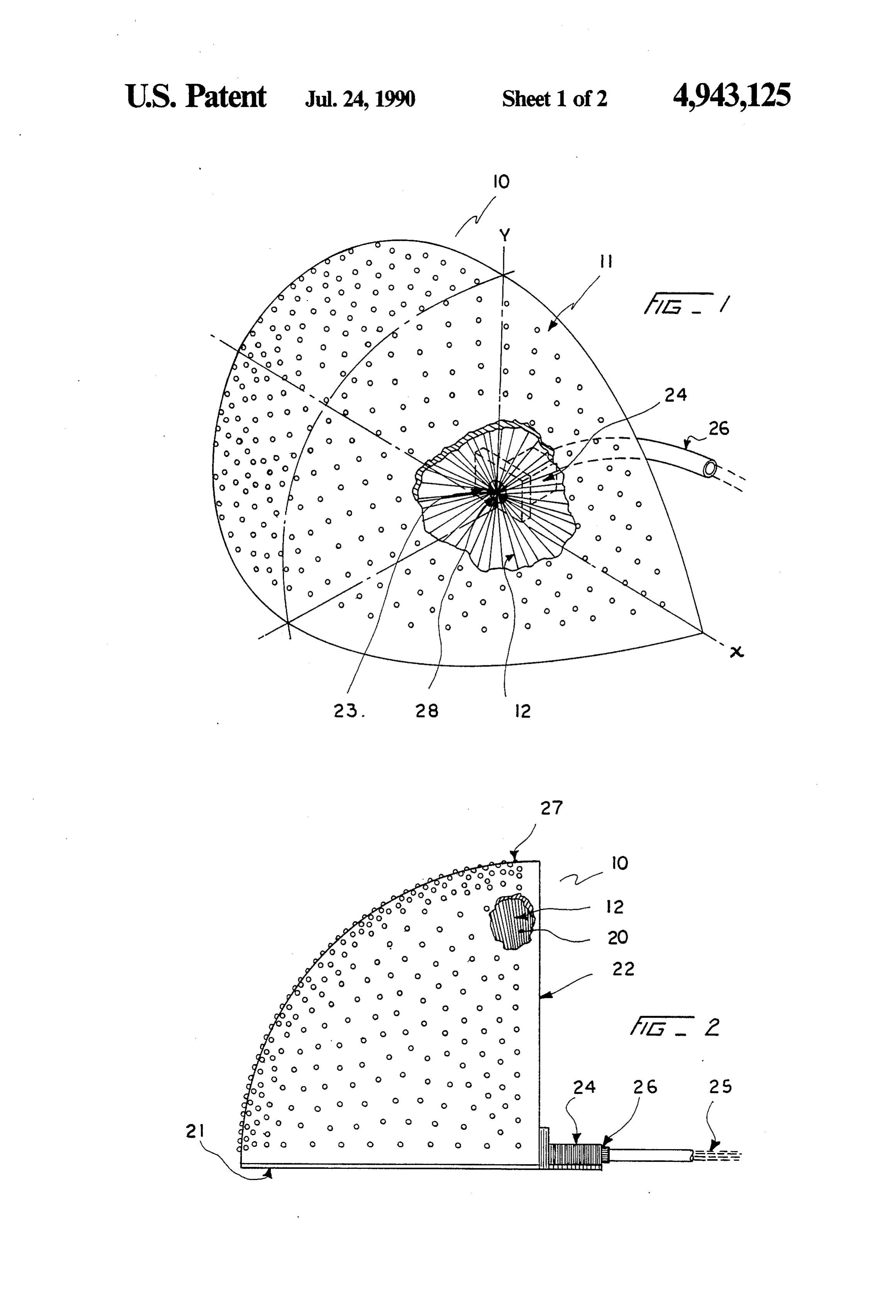
FIG. 2 is a cross-sectional view of the embodiment
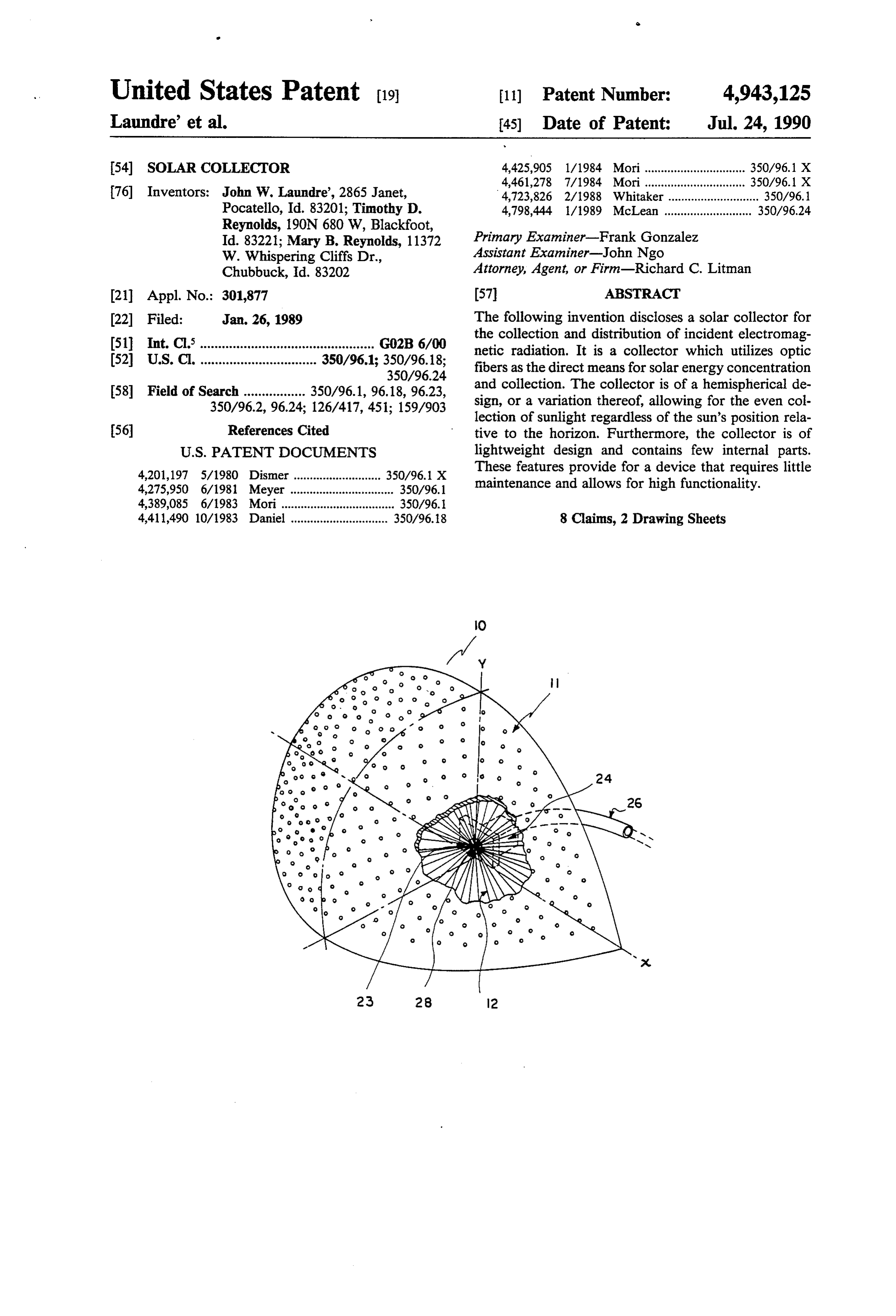
The design does not involve complicated processes for the collection and concentration of solar energy. A presented and in FIG. 1, displaying optic fibers, optic lens, interior cavity location;
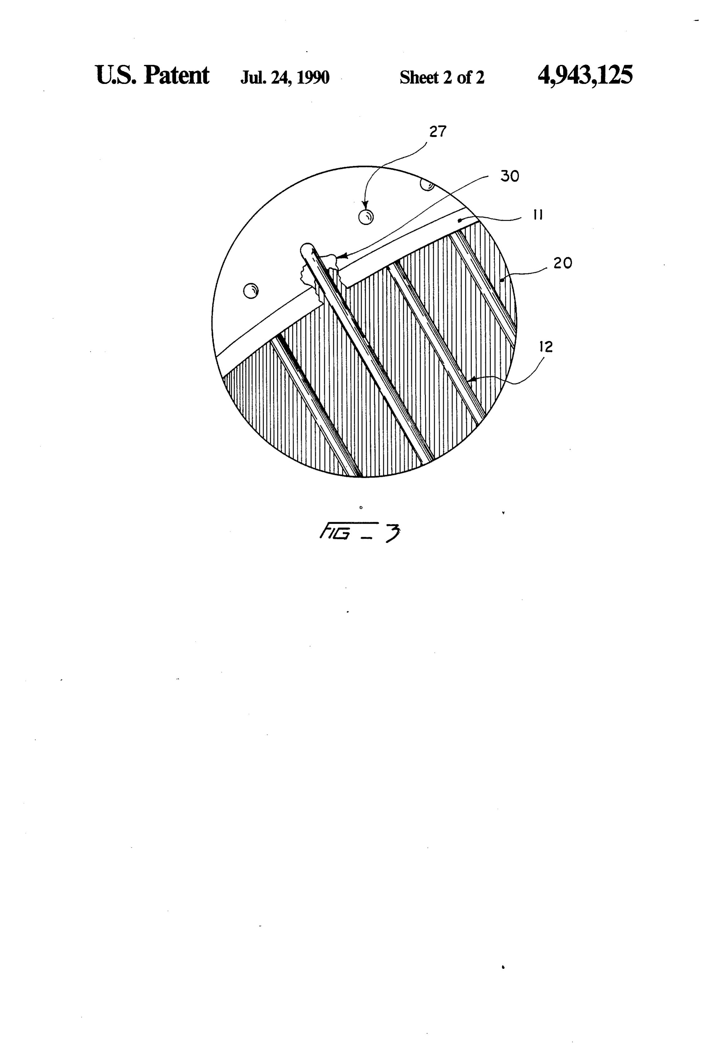
simple lens attached to or formed on the ends of each FIG. 3 is an expanded view of the surface of the exposed optic fiber provides the necessary concentra 35 collector as indicated by FIG. 2, further explaining the tion of radiation. In the case of the present invention, fiber lens and fiber pore correlation. Similar reference the collection device itself is the optic fiber. No addi characters designate corresponding parts throughout tional structures are needed to facilitate collection. This the several figures of the drawings. allows for a relatively inexpensive means for solar col lection. 40 DESCRIPTION OF THE PREFERRED Additionally, the unique hemispherical design allows EMBODIMENT for a constant collection of solar radiation regardless of The description of the preferred embodiment of the the position of the sun, whether this position is due to invention will now be provided with reference to the either daily or seasonal changes. The hemispherical aforementioned drawings, FIG. 1, FIG. 2, and FIG. 3. design assures that at least half of the collector is always 45 The solar collection panel is indicated generally in oriented toward the sun. This means that no tracking FIG. 1 by 10. Solar collection panel 10 includes a plu device is needed to assure that sunlight will be col rality of optic fibers 12 for the collection of solar en lected. It is an essential feature of immediate benefits ergy. A plurality of the optic fibers 12 end in a convex that the design of the present invention lends itself to a shape forming an optic lens means 27 as indicated by light weight composition as well. Should the solar col 50 FIG 2. The optic lens means 27 increases the collection lector be mounted on the roof of a home or building, the area of each individual optic fiber 12 to allow for the suppor trusses need not be designed to withstand the concentration of the collected solar engergy. compressive and tensile forces associated with a high The optic fibers 12 and the optic lens means 27 are to weight application. Additionally, the light weight fea be comprised of such a material as to provide an effi ture allows for simple and easy installation as the device 55 cient conduit for the collection and transmission of solar itself does not prove cumbersome to the construction radiation. This material may be opticl glass, but it worker. should be noted that the present invention is not limited It is for the reasons described above that this inven solely to such a material. The optic material should be tion is clearly superior to the aforementioned devices. of an appropriate quality as to prevent light dispersal SUMMARY OF THE INVENTION during transmission.
Each optic fiber 12 is disposed through the curved
It is therefore a principal object of the present inven surface 11 of the solar collection panel housing assem tion to provide a simple, inexpensive, practical means bly 10 by an optic fiber pore 30. The optic fiber pore 30 for the collection of solar radiation and the transmission is simply a bore through the curved surface 11. The and distribution of radiation so gathered. 65 curved surface 11 is of such a design that it is hemi It is still further an object of the invention to concen spherical or any variation thereof from a small sliver to trate the solar radiation by means of a simple lens sys a full sphere. This design provides for the even collec tem attached to or formed on the optic fiber ends before tion of solar radiation regardless of the position of the
Page 6
Sun to the horizon. The curved surface 11 is the main a plurality of optic fibers which extend from said feature of the housing assembly 10. In addition to the exterior surface of said optic fiber pores to a central curved surface 11, the housing assembly 10 is further location within said interior cavity; defined by two additional structures as shown in FIG. an assemblage of optic fiber segments within said 2: the base structure 21 and, for less than a hemisphere interior cavity at said central location; design, the side structure 22. The housing assembly 10 a means for providing an exit aperture at said assem as assembly encloses the interior cavity 20 as shown in blage of said optic fiber segments for the collection FIG. 2. and concentration of said optic fibers; The side structure 22 and the base structure 21 are an optic fiber clamping means for the collection, simply flat pieces of material. They are used to enclose O gathering, and holding fixed said optic fibers; the interior cavity 20 and to protect the collector parts an energy transmission means attached to said hous located therein from the effect of weather. These struc ing assembly;
tures also prevent the buildup of dirt and other materials a coupling means for the connection to said energy within the interior cavity 20 such that the effectiveness 15 transmission means providing for the distribution of the optic fibers 12 located therein is not affected. of said incident electromagnetic radiation to prede The optic fibers 12 extend from the housing assembly termined application.
10 curved structure 11 to an optic fiber assemblage 23 housing 2. An apparatus according to claim 1 wherein, said where they are gathered. From this point, the optic is comprised of a light weight material. fibers 12 proceed through the exist aperture 28 to the 20 3. An apparatus according to claim 1 wherein, said optic fiber clamping means 24 where the optic fibers 12 plurality of optic fibers is positioned within each of said are held fixed. The optic fiber clamping means 24 in optic fiber pores such that the exposed ends of said optic cludes a coupling means 26 for the connection of an fibers protrude or are at least flush with said exterior energy transmission means 25. The energy transmission surface and may protrude a predetermined distance therebeyond.
means 25 is the equivalent of an optic fiber cable. It allows for the transmission and distribution of the col 25 4. An apparatus according to claim 1 wherein, said lected solar energy. plurality of optic fiber pores are disposed in a pattern The inclusion of an optic fiber clamping means 24 is whereby is evenly the infrared band of electromagnetic radiation collected.
included to hold fixed the optic fibers 12 within the 5. An apparatus according to claim 1 wherein, said housing assembly 10. This allows the internal members, 30 plurality of optic fibers especially the optic fibers 12, to be held rigidly. Such a nal end which functionsincludes as an a hemispherical termi optic condensing lens.
feature assures that the collector will perform to expec 6. An apparatus accoriding to claim 1 wherein, said tations when installed. The optic fiber clamping means curved body surface is of a configuration defined be 24 prevents the displacement ofth optic fibers 12 during tween the limits of a fraction of a sphere to a complete transportation and in the event of severe weather condi 35 sphere.
tions. 7. An apparatus according to claim 6 wherein, The embodiments of the present invention have been said housing assembly defines the space of a quar shown and described herein. It is understood well that tersphere, any variations of the invention as described may be said exist aperture lies at the base of said side struc made by those skilled in the art without departing ture or said base structure perpendicular to a refer fromm the scope and spirit of the present invention as ence plane defined by said base structure, and disclosed. said exit aperture lies at the midpoint between the We claim: radial ends of said side structure as defined by the 1. An apparatus for the collection and transmission of intersection of said side structure with said base incident electromagnetic energy, comprising: 45 Structure.
a housing assembly; 8. An apparatus according to claim 6, wherein, said housing assembly including a curved structured said housing assembly defines the space of a hemi with opposed interior and exterior surfaces; sphere, and said housing assembly defining an interior cavity; said exit aperture lies such that its center point is at a plurality of optic fiber pores included in said exte 50 the radial center of said base structure or said side rior surface of said curved structure and disposed Structure.
therethrough; K :
Provenance
- Collection
- Patents citing this work
- Pages
- 6
- Method
- pdftotext (the PDF's own text layer) + pdftoppm 300dpi page scans
- Patent office record
- patents.google.com →
- Source
- Google Patents citing-documents table
- Assignee
- Laundre John W
- Inventors
- John W. Laundre'; Timothy D. Reynolds; Mary B. Reynolds
- Published
- 1990-07-24
- Transcribed from
- patentimages.storage.googleapis.com →