patent · US2548745
Electrolytic rheostat
10 April 1951
Page 1
Drawing sheet — no readable text.
Page 2
Patented Apr. 10, 1951 2,548,745
UNITED STATES PATENT OFFICE
ELECTROLYTIC RHEOSTAT
Victor H. Smith, Phoenix, Ariz.
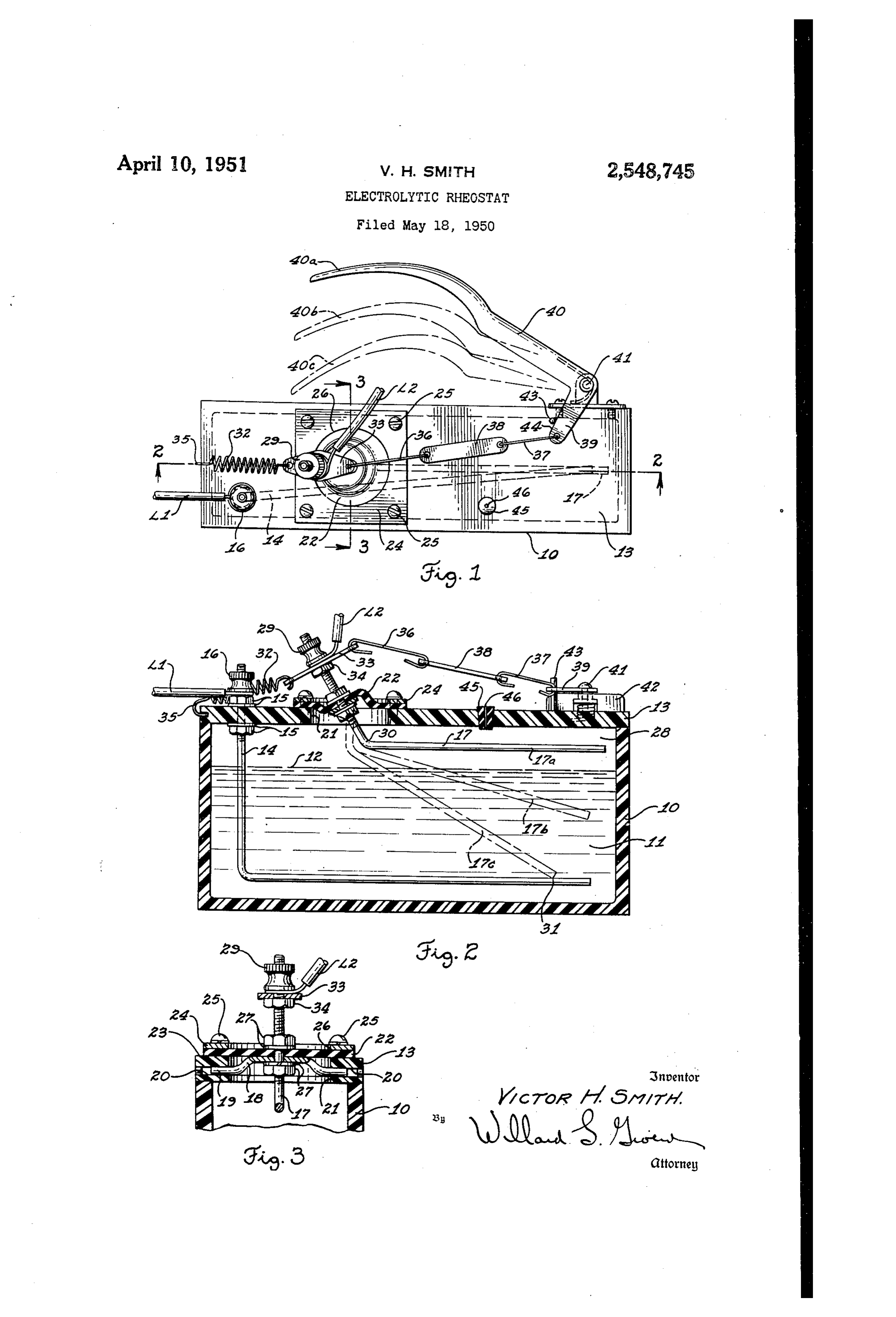
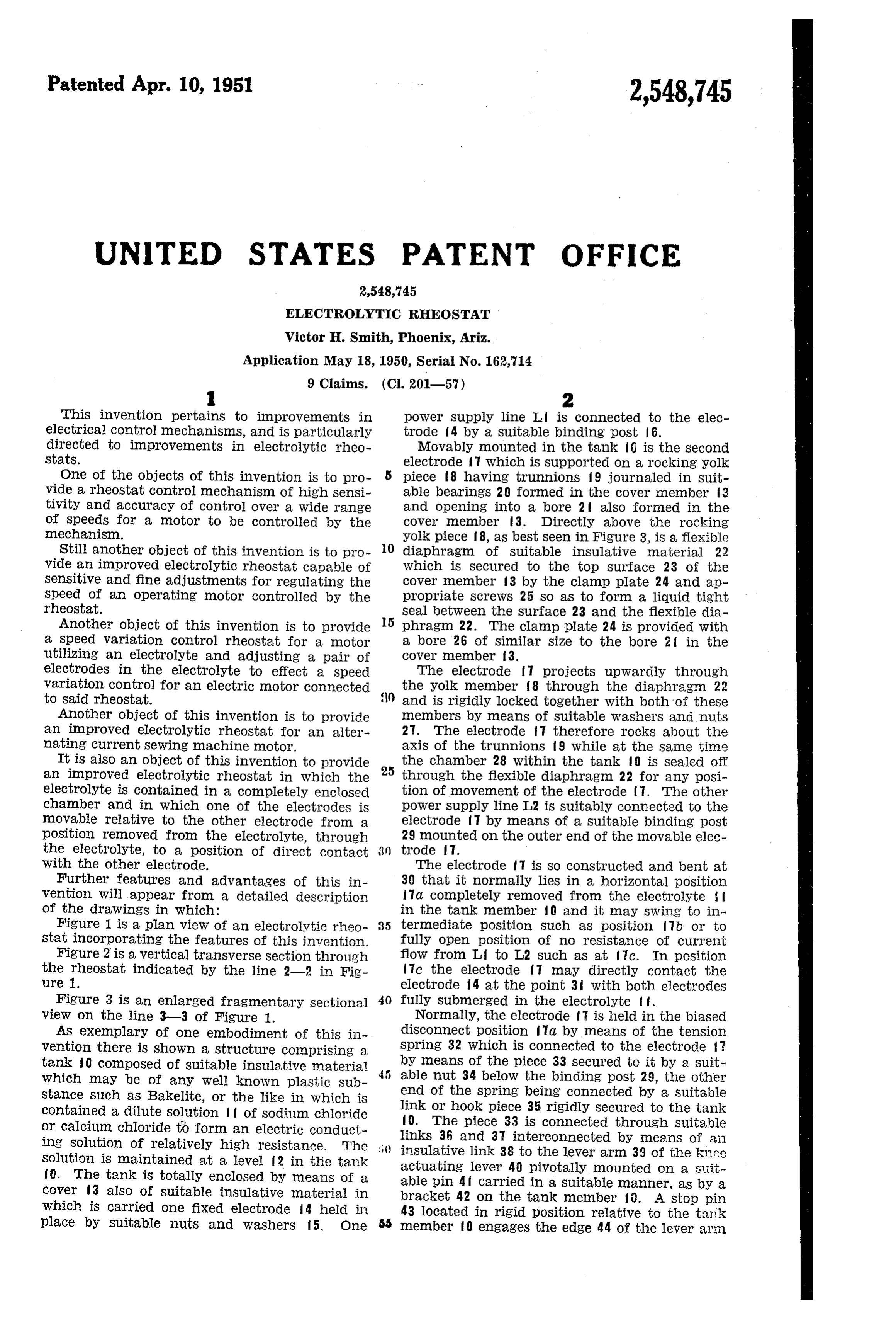
This invention pertains to improvements in power supply line L is connected to the elec electrical control mechanisms, and is particularly trode 4 by a suitable binding post 6. directed to improvements in electrolytic rheo Movably mounted in the tank is the Second Stats. electrode 7 which is supported on a rocking yolk One of the objects of this invention is to pro piece 8 having trunnions 9 journaled in suit vide a rheostat control mechanism of high sensi able bearingS 20 formed in the cover nember 3 tivity and accuracy of control over a wide range and opening into a bore 2 also formed in the of Speeds for a motor to be controlled by the cover member 3. Directly above the rocking mechanism. yolk piece f8, as best seen in Figure 3, is a flexible Still another object of this invention is to pro 0. diaphragm of Suitable insulative material 22 vide an improved electrolytic rheostat capable ofwhich is Secured to the top Surface 23 of the Sensitive and fine adjustments for regulating thecover member 3 by the clamp plate 24 and ap Speed of an operating motor controlled by the propriate screws 25 so as to form a liquid tight rheostat. Seal between the Surface 23 and the flexible dia Another object of this invention is to provide 5 phragm 22. The clamp plate 24 is provided with a Speed variation control rheostat for a motor a bore 26 of Similar size to the bore 2 in the utilizing an electrolyte and adjusting a pair of COver ember 3.
electrodes in the electrolyte to effect a speed The electrode 7 projects upwardly through variation control for an electric motor connected the yolk member 8 through the diaphragm 22 to said rheostat. 0. and is rigidly locked together with both of these Another object of this invention is to provide members by means of suitable washers and nuts an improved electrolytic rheostat for an alter 2. The electrode f therefore rocks about the nating current sewing machine motor. axis of the trunnions 9 while at the same time It is also an object of this invention to provide 25 the chamber 28 within the tank ) is sealed off an improved electrolytic rheostat in which the through the flexible diaphragm 22 for any posi electrolyte is contained in a completely enclosed tion of movement of the electrode 1. The other chamber and in which one of the electrodes is power Supply line T2 is Suitably connected to the movable relative to the other electrode from a electrode 7 by means of a suitable binding post position removed from the electrolyte, through 29 mounted on the outer end of the movable elec the electrolyte, to a position of direct contact trode 7.
With the other electrode. The electrode f l is so constructed and bent at Further features and advantages of this in 3) that it normally lies in a horizontal position vention will appear from a detailed description a completely removed from the electrolyte of the drawings in which: in the tank member 0 and it may swing to in Figure 1 is a plan view of an electrolytic rheo 35 termediate position such as position 7b or to stat incorporating the features of this invention. fully open position of no resistance of current Figure 2 is a vertical transverse section through flow from Li to L2 such as at fic. In position the rheostat indicated by the line 2-2 in Fig ure 1.
fic the electrode 7 may directly contact the electrode f4 at the point 3 with both electrodes
Figure 3 is an enlarged fragmentary sectional 40 fully Submerged in the electrolyte f f. view on the line 3-3 of Figure 1. Normally, the electrode 7 is held in the biased AS exemplary of one embodiment of this in disconnect position fla by means of the tension vention there is shown a structure comprising a Spring 32 which is connected to the electrode tank O composed of suitable insulative material by means of the piece 33 secured to it by a suit which may be of any well known plastic sub able nut 34 below the binding post 29, the other stance Such as Bakelite, or the like in which is end of the Spring being connected by a suitable contained a dilute solution of sodium chloride link or hook piece 35 rigidly secured to the tank or calcium chloride to form an electric conduct f0. The piece 33 is connected through suitable ing Solution of relatively high resistance. The links 36 and 37 interconnected by means of an insulative link 38 to the lever arm 39 of the knee
Solution is maintained at a level 2 in thie tank actuating lever 40 pivotally mounted on a suit f0. The tank is totally enclosed by means of a able pin 4f carried in a suitable manner, as by a Cover 3 also of suitable insulative material in bracket 42 on the tank member . A stop pin which is carried one fixed electrode 4 held in 43 located in rigid position relative to the tank place by Suitable nuts and washers 5. One member fo engages the edge 44 of the lever arm
Page 3
39 so as to limit the normal stop position by the finally to a position of maximum Submergence spring 32 of the electrode to the position a and direct contact with said fixed electrode. shown in Figure 2. A curved knee engaging poi'- 3. In an electrolytic control rheostat having a tion 46a may be provided on the lever if for tank containing a fluid electrolyte, a fixed elec ready operation of the rheostat by the Operator 5 trode submerged in said electrolyte and rigidly of a sewing machine or any other machine being mounted on said tank, a nowable electrode, means driven by a motor energized through the rheo for movably mounting said movable electrode on Stat. said tank, yielding means for normally holding The Solution. in the tank nerinber is nor said movable electrode in a disconnected position mally hermetically sealed off in the tank by 10 out of said electrolyte, and an operating lever means of a suitable rubber cork or closure cap 5 connected to said movable electrode to move it which may contain a microscopic vent hole 66 to into and through said electrolyte. allow for contraction and expansion of the liquid 4. In an electrolytic control rheostat having a if and gas pressure or air in the chamber 28. tank containing a fluid electrolyte, a fixed elec The opening 46 may be of Such Sinall size hOW trode submerged in Said electrolyte and rigidly ever that the liquid cannot escape there mounted on said tank, a movable electrode, means through though the gas in the chamber 28 may for movably mounting said movable electrode on be readily vented through the cork 5. said tank, yielding means for normally holding With the lines I, and L2 connected in Series said movable electrode in a disconnected position With one power Supply line of a source of power 20 out of said electrolyte, and an operating lever and With one terminal of an electric motor or connected to said movable electrode to move it other device to be controlled, the Switch may be into and through said electrolyte to a position of operated from a no current flow position of the engagement with said fixed electrode. control lever 40 as shown at Aa. With the electrode 5. In ain electrolytic rheostat having a tank in the position a to engage the electrode 25 containing fluid electrolyte, a fixed electrode sub with the solution f in varying degrees. At vari merged in said electrolyte, a movable electrode, ous intermediate positions to the notor or device means for movably mounting Said movable elec may be energized more or less to effect its Speed trode on said tank comprising a trunnion member of operation with an extreme nicety and precise pivotally journaled on said tank, a flexible dia ness of Speed regulation being obtained. Finally 30 phragm Secured to said tank, and means Securing as greater and greater Speeds are desired aS in Said nowable electrode, trunnion inenber, and noving the control lever from position 4 b down said diaphragm rigidly together to provide Sup to position 49c, the electrode is finally brought port for said movable electrode on said tank. into direct contact with the electrode 4 at the 6. In an electrolytic rheostat having a tank point 3 to give full voltage nonresistance con 35 containing merged in fluid electrolyte, a fixed electrode Sub said electrolyte, a movable electrode, nection through the rheostat from lines L. to T.2 for maximum power and full Speed operation of Imeans for movably mounting Said inovable elec the machine being controlled. It is to be further trode on Said tank comprising a trunnion men noted that in this arrangement the initial Stages ber pivotally journaled on said tank, a flexible diaphragm Secured to Said tank, and means Se of contact between position Act and Fab of the 40 curing electrode With the Surface 2 of the Solution said movable electrode, trunnion member, takes place at a greater rate and Sensitivity than and said diaphragm rigidly together to provide relative movement from position b to c. Support for said movable electrode on Said tank, his results in excellent low Speed range control bias spring means connected to said movable elec for the device connected to be controlled by this 45 trode to normally yieldingly hold said movable improved electrolytic rheostat. electrode in a disconnected position out of said Having thus fully described this invention and electrolyte, and an actuating lever pivotally its numerous attendant advantages, it is obvious mounted relative to said tank and connected by that many changes may be made in the form, linkage lineans to Said nowable electrode for now construction and arrangement of the parts With 50 ing said movable electrode into and through said electrolyte and into engagement With Said fixed out departing from the Spirit or Scope of the in vention or sacrificing its attendant advantages, electrode, the form herein described being a preferred em 7. In an electrolytic rheostat having a tank, bodiment for purposes of exemplifying this in an electrolyte in Said tank, electrodes in said tank Vention. movable relative to each other in said electrolyte, What is claimed is: and means for Sealing Said tank comprising a 1. Ain electrolytic rheostat comprising a tank, resilient plastic Cork or the like having a micro a cover fixed on said tank, an electrolyte in said Scopic Weint therein Secured in an access, opening of Said tank.
tank, a fixed electrode supported from said cover 60 8. In an electrolytic rheostat structure having in Said tank Submerged in Said electrolyte, a a tank, an electrolyte in said tank, a fixed elec nowable electrode, means for mounting Said now trode having a horizontal member located in said able electrode on said cover, and means for actu electrolyte near the bottom of said tank, a mov atting said movable electrode from a position able electrode pivotally mounted at the top of above the electrolyte in said tank to intermediate 65 Said tank having a member normally held in positions of partial Submergence in Said electro horizontal position at the top of said tank and lyte. above Said electrolyte, and means for pivotally 2. An electrolytic rheostat comprising a tank, actuating said movable electrode to swing its an electrolyte in Said tank, a fixed electrode in Outer end downwardly through said electrolyte Said tank Submerged in Said electrolyte, a mov 70 relative to the horizontal member of said fixed able electrode, means for mounting said movable electrode.
electrode on Said tank, and means for actuating 9. In an electrolytic rheostat structure having Said movable electrode from a position above the a tank, an electrolyte in said tank, a fixed elec electrolyte in Said tank to intermediate positions trode having a horizontal member located in said of partial Submergence in Said electrolyte, and 75 electrolyte near the bottom of said tank, a mov
Page 4
able electrode pivotally mounted at the top of REFERENCES CITED Said tank having a member normally held in The following references are of record in the horizOntal position at the top of Said tank and file of this patent:
above Said electrolyte, and means for pivotally actuating said movable electrode to swing its UNITED STATES PATENTS outer end downwardly through said electrolyte Number Name Date relative to the horizontal member of Said fixed 475,255 Sterling ------------ May 17, 1892 electrode and finally into direct contact With Said FOREIGN PATENTS horizontal member of Said fixed electrode.
VICTOR, H. SMITH. 705,860 France ------------- June 16, 1931
Provenance
- Collection
- Cited prior art
- Original PDF
- patentimages.storage.googleapis.com →
- Filed
- 1950-05-18
- Pages
- 4
- Method
- pdftotext (the PDF's own text layer) + pdftoppm 300dpi page scans
- Source
- Google Patents bibliographic record
- Granted
- 1951-04-10
- Inventors
- Victor H Smith
- Transcribed from
- patentimages.storage.googleapis.com →