patent · US5531865
Electrolytic water purification process
2 July 1996
Page 1 — bibliographic record
United States Patent (19) 11) Patent Number: 5,531,865 Cole (45. Date of Patent: Jul. 2, 1996 54 ELECTROLYTICWATER PURIFICATION 4,623,436 11/1986 Umehara ................................. 204/149 PROCESS 4,857,198 8/1989 Meidl ........ 210/603 4,960.520 10/1990 Semmens ............................... 210/640 76 Inventor: Leland G. Cole, 1667 Lake Front Rd., FOREIGN PATENT DOCUMENTS Lake Oswego, Oreg. 97034
(21) Appl. No.: 395.917 Primary Examiner-Arun S. Phasge (22 Filed: Feb. 28, 1995 Attorney, Agent, or Firm-Flehr, Hohbach, Test, Albritton & Herbert
Related U.S. Application Data (57) ABSTRACT 63 Continuation-in-part of Ser. No. 279,629, Jul. 25, 1994, A method for removing contaminants from a flow of waste abandoned, which is a continuation of Ser. No. 932,316, water using an electrolytic oxidation vessel having a cham Aug. 19, 1992, abandoned. ber and at least one elongate cathode electrode and a (51 Int. Cl. ............................. C02F 1/463; CO2F 11461 plurality of elongate sacrificial anode electrodes aligned 52 U.S. Cl. .......................... 205/751; 205/761; 204/269; parallel with the cathode electrode in the chamber. The flow 204/275; 210/667 of wastewater is directed through the chamber of the elec 58) Field of Search ..................................... 204/149, 152, trolytic oxidation vessel in a direction parallel with the cathode and anode electrodes so that the flow of wastewater 204/269, 275; 210/667; 205/751, 761 engages the cathode and anode electrodes. A voltage is 56 References Cited applied across the cathode electrode and the sacrificial anode electrodes to create a current having a density ranging from
anode electrodes which oxidize and render insoluble con 3,926,754 12/1975 Lee .......................................... 204/152 taminants in the flow of wastewater and create insoluble 3,933,606 1/1976 Harms ..................................... 204/152 3,959,129 5/1976 White et al. .............................. 210/28 contaminants and substantially cleansed water. The 4,152.229 5/1979 Soltys et al. ... . 204/150 insoluble contaminants are separated from the substantially 4, 194972 3/1980 Weintraub et al. . ... 210/43 cleansed water. An apparatus for use with the method is 4,271,028 6/1981 Marfurt et al. ......................... 210/727 provided.
4.293,400 10/1981 Liggett .................................... 204/302 4,330,513 5/1982 Hunter et al. ........................... 423/245 31 Claims, 3 Drawing Sheets
EQUALIZATION
TANK
SEPARATOR REACTOR
vocREACTOR oxidATION STRIPPER
FOCCUANT
RECYCLE TO
VACUUM
FILTER
SOLDIFICATION; SLUDGE
Page 2
Drawing sheet — no readable text.
Page 3
Drawing sheet — no readable text.
Page 4
Drawing sheet — no readable text.
Page 5
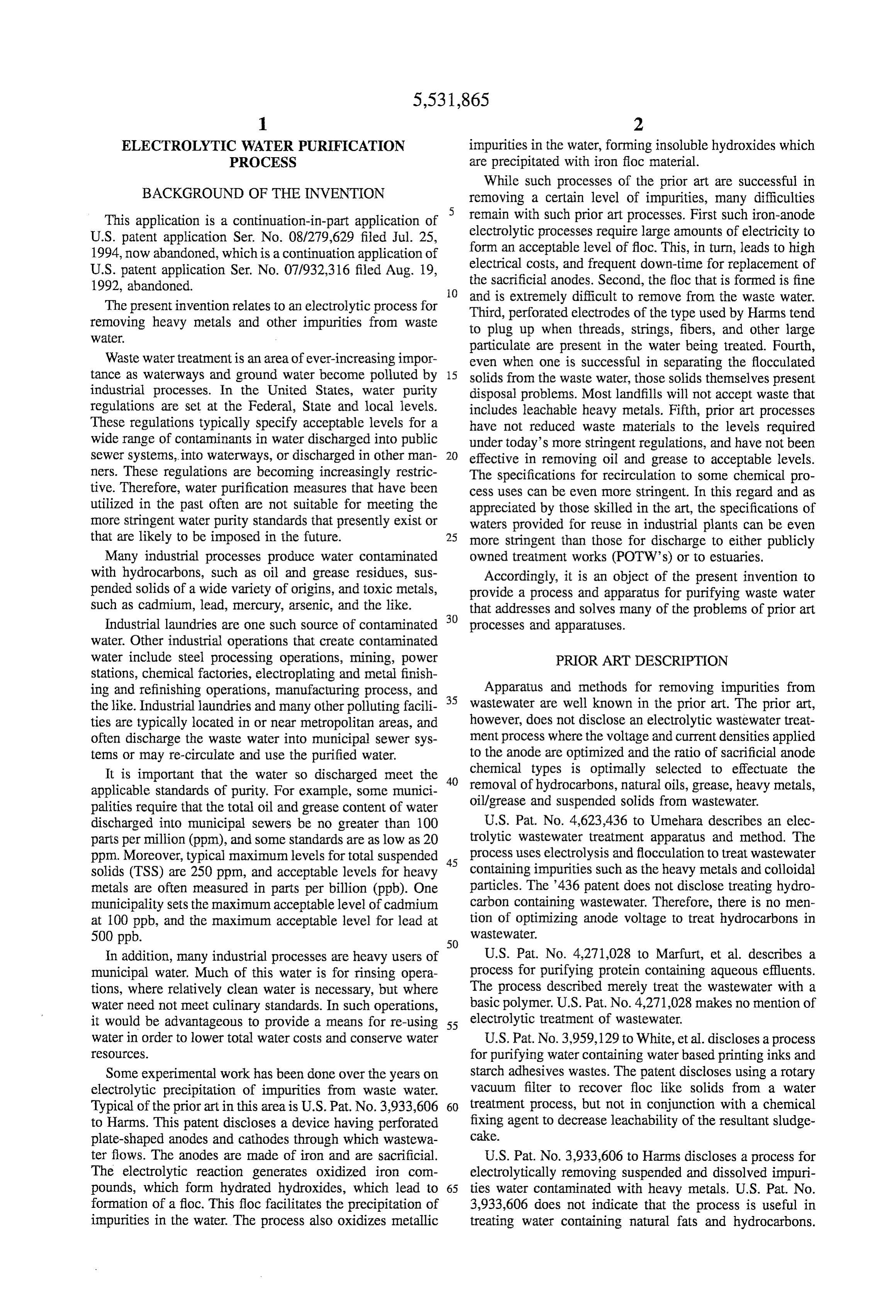
ELECTROLYTICWATER PURIFICATION impurities in the water, forming insoluble hydroxides which PROCESS are precipitated with iron floc material.
While such processes of the prior art are successful in
BACKGROUND OF THE INVENTION removing a certain level of impurities, many difficulties This application is a continuation-in-part application of remain with such prior art processes. First such iron-anode
1994, now abandoned, which is a continuation application of form an acceptable level of floc. This, in turn, leads to high
1992, abandoned. the sacrificial anodes. Second, the floc that is formed is fine O and is extremely difficult to remove from the waste water.
The present invention relates to an electrolytic process for Third, perforated electrodes of the type used by Harms tend removing heavy metals and other impurities from waste to plug up when threads, strings, fibers, and other large Water.
particulate are present in the water being treated. Fourth,
Waste water treatment is an area of ever-increasing impor even when one is successful in separating the flocculated tance as waterways and ground water become polluted by 15 solids from the waste water, those solids themselves present industrial processes. In the United States, water purity disposal problems. Most landfills will not accept waste that regulations are set at the Federal, State and local levels. includes leachable heavy metals. Fifth, prior art processes These regulations typically specify acceptable levels for a have not reduced waste materials to the levels required wide range of contaminants in water discharged into public under today's more stringent regulations, and have not been sewer systems, into waterways, or discharged in other man 20 effective in removing oil and grease to acceptable levels. ners. These regulations are becoming increasingly restric The specifications for recirculation to some chemical pro tive. Therefore, water purification measures that have been cess uses can be even more stringent. In this regard and as utilized in the past often are not suitable for meeting the appreciated by those skilled in the art, the specifications of more stringent water purity standards that presently exist or waters provided for reuse in industrial plants can be even that are likely to be imposed in the future. 25 more stringent than those for discharge to either publicly Many industrial processes produce water contaminated owned treatment works (POTWs) or to estuaries. with hydrocarbons, such as oil and grease residues, sus Accordingly, it is an object of the present invention to pended solids of a wide variety of origins, and toxic metals, provide a process and apparatus for purifying waste water such as cadmium, lead, mercury, arsenic, and the like. that addresses and solves many of the problems of prior art Industrial laundries are one such source of contaminated 30 processes and apparatuses.
water. Other industrial operations that create contaminated water include steel processing operations, mining, power PRIOR ART DESCRIPTION stations, chemical factories, electroplating and metal finish ing and refinishing operations, manufacturing process, and Apparatus and methods for removing impurities from the like. Industrial laundries and many other polluting facili 35 wastewater are well known in the prior art. The prior art, ties are typically located in or near metropolitan areas, and however, does not disclose an electrolytic wastewater treat often discharge the waste water into municipal sewer sys ment process where the voltage and current densities applied tens or may re-circulate and use the purified water. to the anode are optimized and the ratio of sacrificial anode It is important that the water so discharged meet the 40 chemical types is optimally selected to effectuate the removal of hydrocarbons, natural oils, grease, heavy metals, applicable standards of purity. For example, some munici oil/grease and suspended solids from wastewater. palities require that the total oil and grease content of water discharged into municipal sewers be no greater than 100 U.S. Pat. No. 4,623,436 to Umehara describes an elec parts per million (ppm), and some standards are as low as 20 trolytic wastewater treatment apparatus and method. The ppm. Moreover, typical maximum levels for total suspended 45 process uses electrolysis and flocculation to treat wastewater solids (TSS) are 250 ppm, and acceptable levels for heavy containing impurities such as the heavy metals and colloidal metals are often measured in parts per billion (ppb). One particles. The 436 patent does not disclose treating hydro municipality sets the maximum acceptable level of cadmium carbon containing wastewater. Therefore, there is no men at 100 ppb, and the maximum acceptable level for lead at tion of optimizing anode voltage to treat hydrocarbons in 500 ppb. 50
WasteWater.
In addition, many industrial processes are heavy users of U.S. Pat. No. 4,271,028 to Marfurt, et al. describes a municipal water. Much of this water is for rinsing opera process for purifying protein containing aqueous effluents. tions, where relatively clean water is necessary, but where The process described merely treat the wastewater with a water need not meet culinary standards. In such operations, basic polymer. U.S. Pat. No. 4,271,028 makes no mention of it would be advantageous to provide a means for re-using 55 electrolytic treatment of wastewater.
water in order to lower total water costs and conserve water U.S. Pat. No. 3,959,129 to White, et al. discloses a process CSOCCS. for purifying water containing water based printing inks and Some experimental work has been done over the years on starch adhesives wastes. The patent discloses using a rotary electrolytic precipitation of impurities from waste water. vacuum filter to recover floc like solids from a water Typical of the prior art in this area is U.S. Pat. No. 3,933,606 60 treatment process, but not in conjunction with a chemical to Harms. This patent discloses a device having perforated fixing agent to decrease leachability of the resultant sludge plate-shaped anodes and cathodes through which wastewa cake.
ter flows. The anodes are made of iron and are sacrificial. U.S. Pat. No. 3,933,606 to Harms discloses a process for The electrolytic reaction generates oxidized iron com electrolytically removing suspended and dissolved impuri pounds, which form hydrated hydroxides, which lead to 65 ties water contaminated with heavy metals. U.S. Pat. No. formation of a floc. This floc facilitates the precipitation of 3,933,606 does not indicate that the process is useful in impurities in the water. The process also oxidizes metallic treating water containing natural fats and hydrocarbons.
Page 6
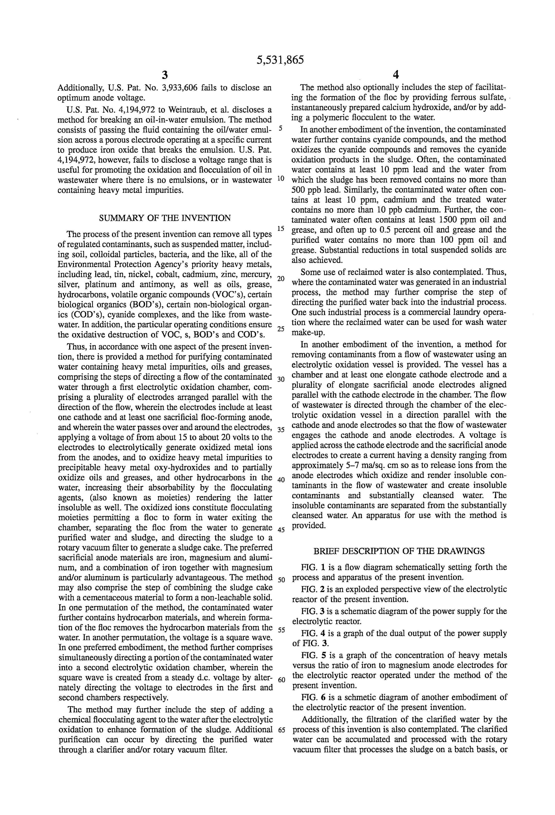
Additionally, U.S. Pat. No. 3,933,606 fails to disclose an The method also optionally includes the step of facilitat optimum anode voltage. ing the formation of the floc by providing ferrous sulfate, . U.S. Pat. No. 4,194,972 to Weintraub, et al. discloses a instantaneously prepared calcium hydroxide, and/or by add method for breaking an oil-in-water emulsion. The method ing a polymeric flocculent to the water. consists of passing the fluid containing the oil/water emul In another embodiment of the invention, the contaminated sion across a porous electrode operating at a specific current water further contains cyanide compounds, and the method to produce iron oxide that breaks the emulsion. U.S. Pat. oxidizes the cyanide compounds and removes the cyanide 4,194,972, however, fails to disclose a voltage range that is oxidation products in the sludge. Often, the contaminated useful for promoting the oxidation and flocculation of oil in water contains at least 10 ppm lead and the water from wastewater where there is no emulsions, or in wastewater O which the sludge has been removed contains no more than containing heavy metal impurities. 500 ppb lead. Similarly, the contaminated water often con tains at least 10 ppm, cadmium and the treated water contains no more than 10 ppb cadmium. Further, the con
SUMMARY OF THE INVENTION taminated water often contains at least 1500 ppm oil and 15 grease, and often up to 0.5 percent oil and grease and the
The process of the present invention can remove all types purified water contains no more than 100 ppm oil and of regulated contaminants, such as suspended matter, includ grease. Substantial reductions in total suspended solids are ing soil, colloidal particles, bacteria, and the like, all of the also achieved.
Environmental Protection Agency's priority heavy metals, including lead, tin, nickel, cobalt, cadmium, Zinc, mercury, 20 Some use of reclaimed water is also contemplated. Thus, silver, platinum and antimony, as well as oils, grease, where the contaminated water was generated in an industrial hydrocarbons, volatile organic compounds (VOCs), certain process, the method may further comprise the step of biological organics (BOD’s), certain non-biological organ directing the purified water back into the industrial process. ics (COD's), cyanide complexes, and the like from waste One such industrial process is a commercial laundry opera water. In addition, the particular operating conditions ensure 25 tion where the reclaimed water can be used for wash water the oxidative destruction of VOC, s, BOD's and COD's. make-up.
Thus, in accordance with one aspect of the present inven In another embodiment of the invention, a method for tion, there is provided a method for purifying contaminated removing contaminants from a flow of wastewater using an water containing heavy metal impurities, oils and greases, electrolytic oxidation vessel is provided. The vessel has a comprising the steps of directing a flow of the contaminated 30 chamber and at least one elongate cathode electrode and a water through a first electrolytic oxidation chamber, com plurality of elongate sacrificial anode electrodes aligned prising a plurality of electrodes arranged parallel with the parallel with the cathode electrode in the chamber. The flow direction of the flow, wherein the electrodes include at least of wastewater is directed through the chamber of the elec one cathode and at least one sacrificial floc-forming anode, trolytic oxidation vessel in a direction parallel with the and wherein the waterpasses over and around the electrodes, 35 cathode and anode electrodes so that the flow of wastewater applying a voltage of from about 15 to about 20 volts to the engages the cathode and anode electrodes. A voltage is electrodes to electrolytically generate oxidized metal ions applied across the cathode electrode and the sacrificial anode from the anodes, and to oxidize heavy metal impurities to electrodes to create a current having a density ranging from precipitable heavy metal oxy-hydroxides and to partially approximately 5-7 ma/sq. cm so as to release ions from the oxidize oils and greases, and other hydrocarbons in the 40 anode electrodes which oxidize and render insoluble con water, increasing their absorbability by the flocculating taminants in the flow of wastewater and create insoluble agents, (also known as moieties) rendering the latter contaminants and substantially cleansed water. The insoluble as well. The oxidized ions constitute flocculating insoluble contaminants are separated from the substantially moieties permitting a floc to form in water exiting the cleansed water. An apparatus for use with the method is chamber, separating the floc from the water to generate 45 provided.
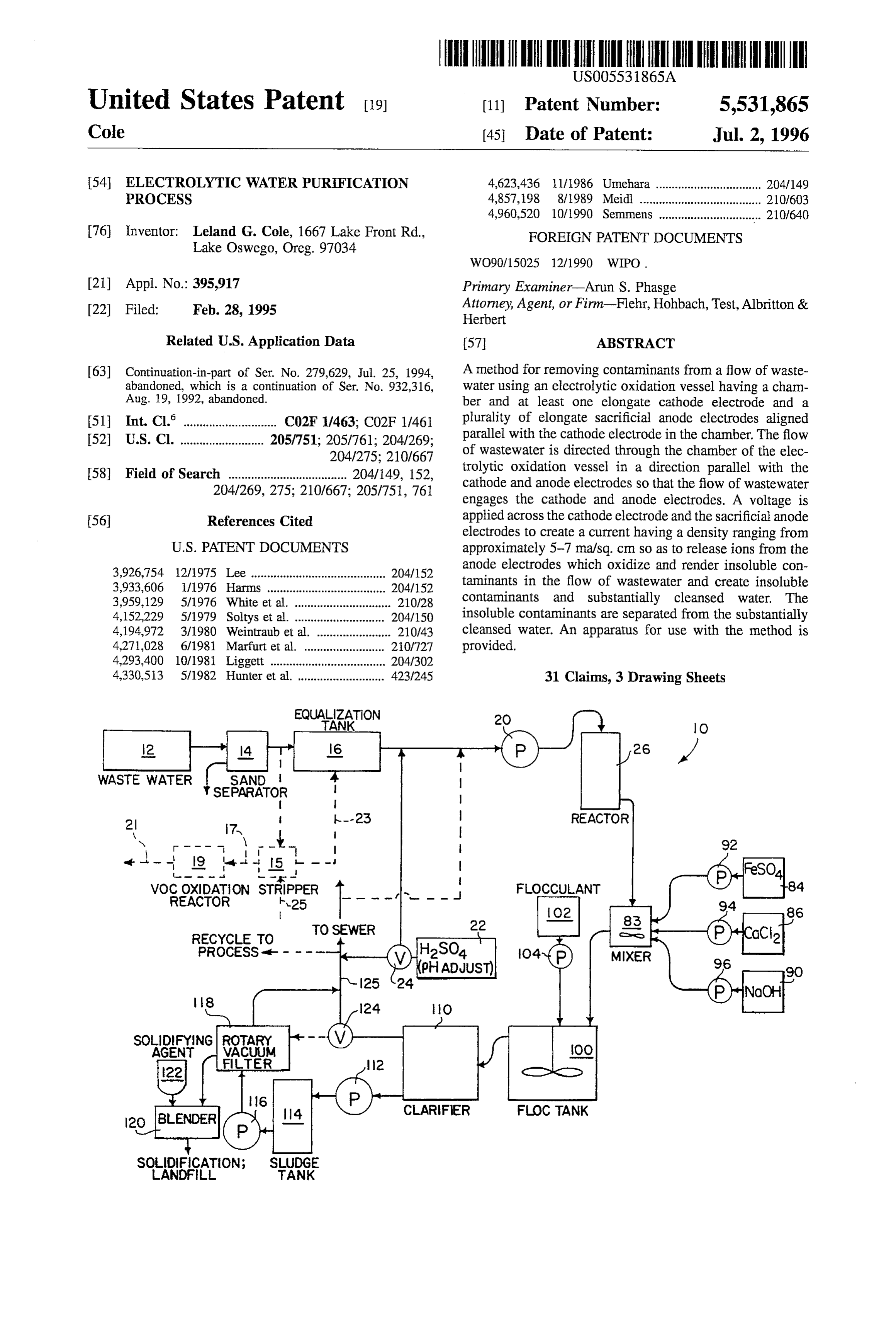
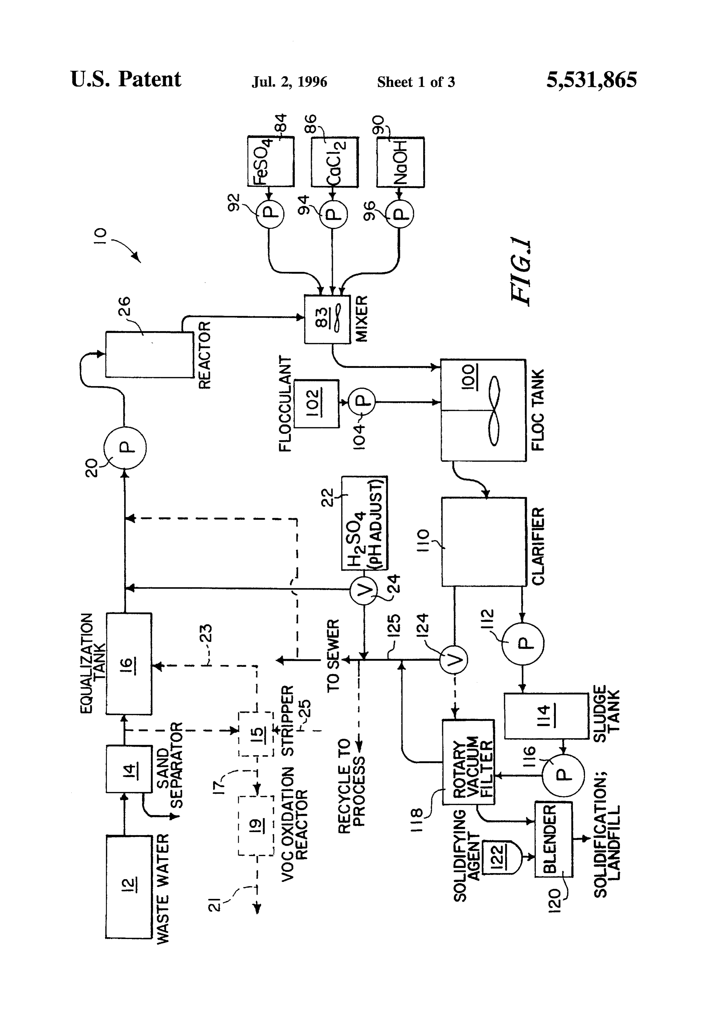
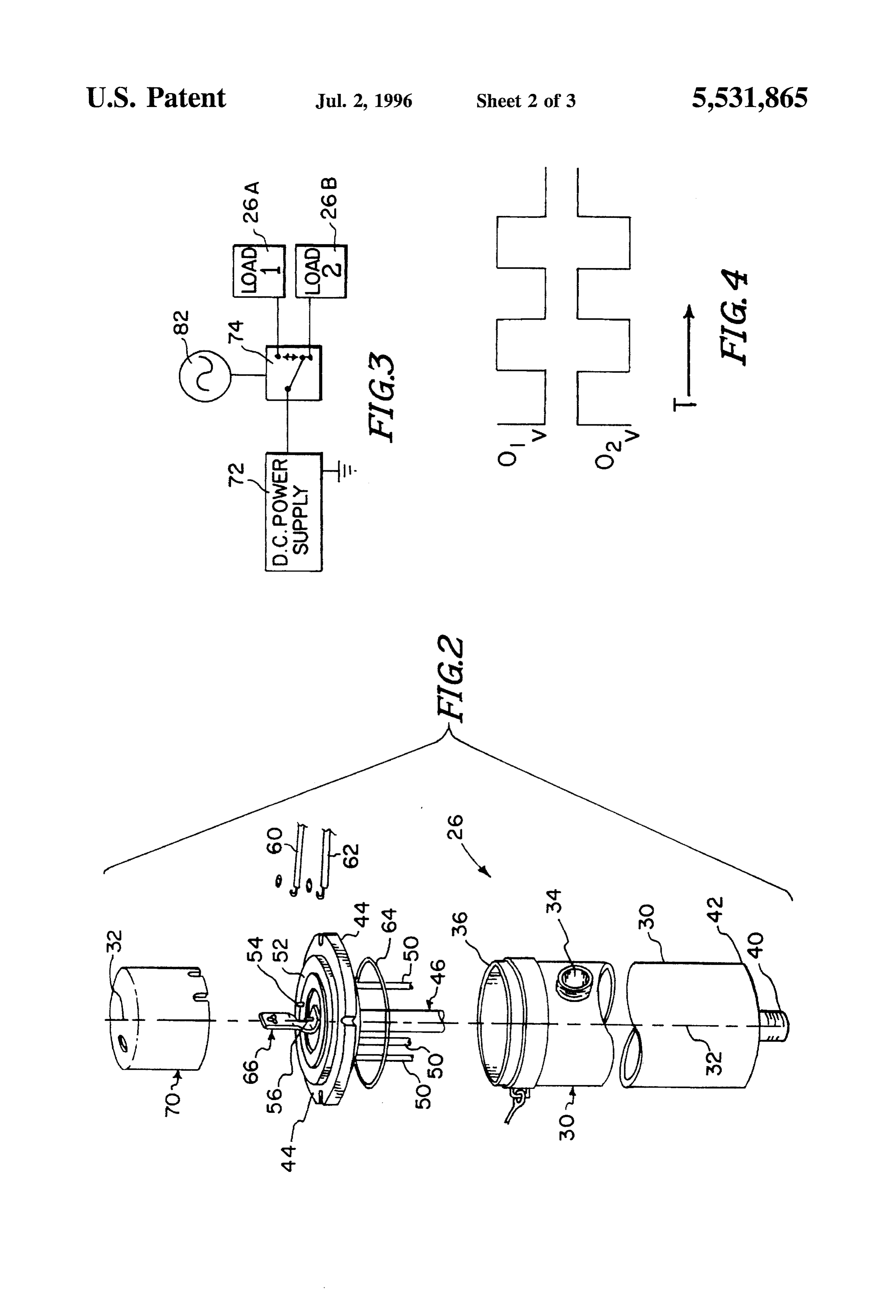
purified water and sludge, and directing the sludge to a rotary vacuum filter to generate a sludge cake. The preferred BRIEF DESCRIPTION OF THE DRAWINGS sacrificial anode materials are iron, magnesium and alumi num, and a combination of iron together with magnesium FIG. 1 is a flow diagram schematically setting forth the and/or aluminum is particularly advantageous. The method 50 process and apparatus of the present invention. may also comprise the step of combining the sludge cake FIG. 2 is an exploded perspective view of the electrolytic with a cementaceous material to form a non-leachable solid. reactor of the present invention. In one permutation of the method, the contaminated water FIG. 3 is a schematic diagram of the power supply for the further contains hydrocarbon materials, and wherein forma electrolytic reactor.
tion of the floc removes the hydrocarbon materials from the 55 FIG. 4 is a graph of the dual output of the power supply water. In another permutation, the voltage is a square wave. of FIG. 3.
In one preferred embodiment, the method further comprises simultaneously directing a portion of the contaminated water FIG. 5 is a graph of the concentration of heavy metals into a second electrolytic oxidation chamber, wherein the versus the ratio of iron to magnesium anode electrodes for square wave is created from a steady d.c. voltage by alter 60 the electrolytic reactor operated under the method of the nately directing the voltage to electrodes in the first and present invention.
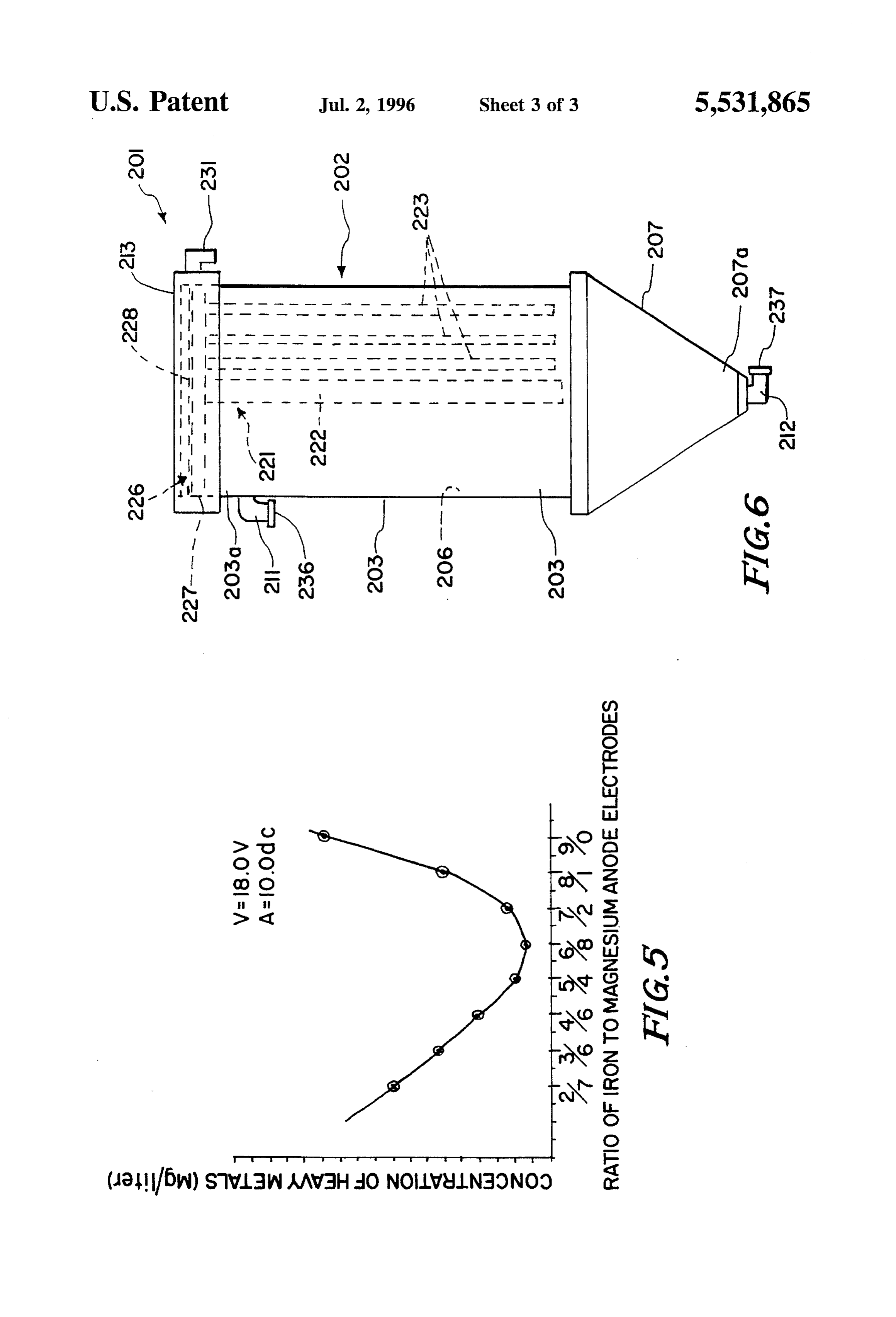
second chambers respectively. FIG. 6 is a schmetic diagram of another embodiment of The method may further include the step of adding a the electrolytic reactor of the present invention. chemical flocculating agent to the water after the electrolytic Additionally, the filtration of the clarified water by the oxidation to enhance formation of the sludge. Additional 65 process of this invention is also contemplated. The clarified purification can occur by directing the purified water water can be accumulated and processed with the rotary through a clarifier and/or rotary vacuum filter. vacuum filter that processes the sludge on a batch basis, or
Page 7
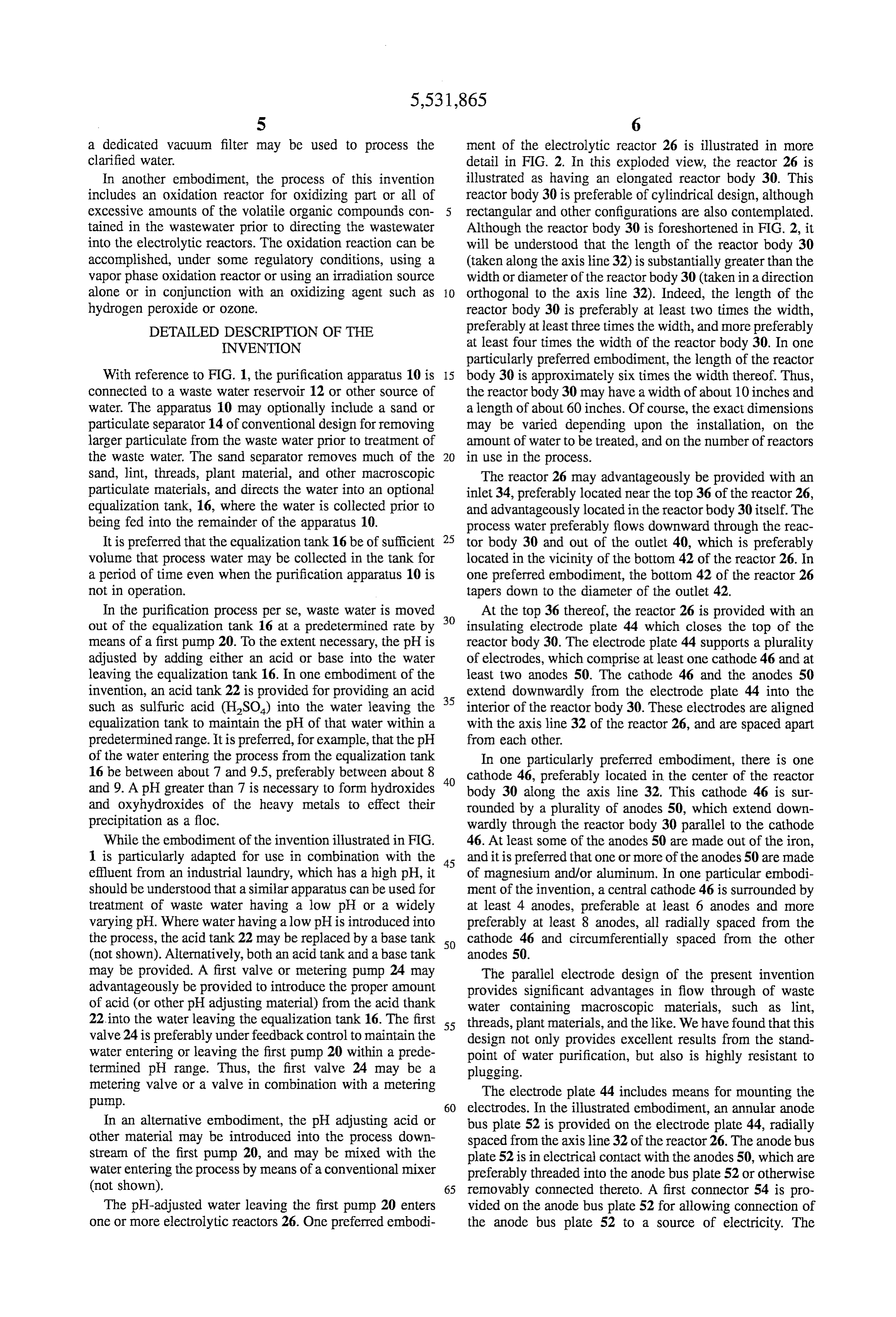
a dedicated vacuum filter may be used to process the ment of the electrolytic reactor 26 is illustrated in more clarified water. detail in FIG. 2. In this exploded view, the reactor 26 is In another embodiment, the process of this invention illustrated as having an elongated reactor body 30. This includes an oxidation reactor for oxidizing part or all of reactor body 30 is preferable of cylindrical design, although excessive amounts of the volatile organic compounds con 5 rectangular and other configurations are also contemplated. tained in the wastewater prior to directing the wastewater Although the reactor body 30 is foreshortened in FIG. 2, it into the electrolytic reactors. The oxidation reaction can be will be understood that the length of the reactor body 30 accomplished, under some regulatory conditions, using a (taken along the axis line 32) is substantially greater than the vapor phase oxidation reactor or using an irradiation source width or diameter of the reactor body 30 (taken in a direction alone or in conjunction with an oxidizing agent such as O orthogonal to the axis line 32). Indeed, the length of the hydrogen peroxide or ozone. reactor body 30 is preferably at least two times the width, DETAILED DESCRIPTION OF THE preferably at least three times the width, and more preferably INVENTION at least four times the width of the reactor body 30. In one particularly preferred embodiment, the length of the reactor
With reference to FIG. 1, the purification apparatus 10 is 15 body 30 is approximately six times the width thereof. Thus, connected to a waste water reservoir 12 or other source of the reactor body 30 may have a width of about 10 inches and water. The apparatus 10 may optionally include a sand or a length of about 60 inches. Of course, the exact dimensions particulate separator 14 of conventional design for removing may be varied depending upon the installation, on the larger particulate from the waste water prior to treatment of amount of water to be treated, and on the number of reactors the waste water. The sand separator removes much of the 20 in use in the process.
sand, lint, threads, plant material, and other macroscopic The reactor 26 may advantageously be provided with an particulate materials, and directs the water into an optional inlet 34, preferably located near the top 36 of the reactor 26, equalization tank, 16, where the water is collected prior to and advantageously located in the reactor body 30 itself. The being fed into the remainder of the apparatus 10. process water preferably flows downward through the reac It is preferred that the equalization tank 16 be of sufficient 25 tor body 30 and out of the outlet 40, which is preferably volume that process water may be collected in the tank for located in the vicinity of the bottom 42 of the reactor 26. In a period of time even when the purification apparatus 10 is one preferred embodiment, the bottom 42 of the reactor 26 not in operation. tapers down to the diameter of the outlet 42. In the purification process per se, waste water is moved At the top 36 thereof, the reactor 26 is provided with an out of the equalization tank 16 at a predetermined rate by 30 insulating electrode plate 44 which closes the top of the means of a first pump 20. To the extent necessary, the pH is reactor body 30. The electrode plate 44 supports a plurality adjusted by adding either an acid or base into the water of electrodes, which comprise at least one cathode 46 and at leaving the equalization tank 16. In one embodiment of the least two anodes 50. The cathode 46 and the anodes 50 invention, an acid tank 22 is provided for providing an acid 35 extend downwardly from the electrode plate 44 into the such as sulfuric acid (H2SO) into the water leaving the interior of the reactor body 30. These electrodes are aligned equalization tank to maintain the pH of that water within a with the axis line 32 of the reactor 26, and are spaced apart predetermined range. It is preferred, for example, that the pH from each other.
of the water entering the process from the equalization tank In one particularly preferred embodiment, there is one 16 be between about 7 and 9.5, preferably between about 8 40 cathode 46, preferably located in the center of the reactor and 9. A pH greater than 7 is necessary to form hydroxides body 30 along the axis line 32. This cathode 46 is sur and oxyhydroxides of the heavy metals to effect their rounded by a plurality of anodes 50, which extend down precipitation as a floc. wardly through the reactor body 30 parallel to the cathode While the embodiment of the invention illustrated in FIG. 46. At least some of the anodes 50 are made out of the iron, 1 is particularly adapted for use in combination with the 45 and it is preferred that one or more of the anodes 50 are made effluent from an industrial laundry, which has a high pH, it of magnesium and/or aluminum. In one particular embodi should be understood that a similar apparatus can be used for ment of the invention, a central cathode 46 is surrounded by treatment of waste water having a low pH or a widely at least 4 anodes, preferable at least 6 anodes and more varying pH. Where water having allow pH is introduced into preferably at least 8 anodes, all radially spaced from the the process, the acid tank 22 may be replaced by a base tank 50 cathode 46 and circumferentially spaced from the other (not shown). Alternatively, both an acid tank and a base tank anodes 50.
may be provided. A first valve or metering pump 24 may The parallel electrode design of the present invention advantageously be provided to introduce the proper amount provides significant advantages in flow through of waste of acid (or other pH adjusting material) from the acid thank water containing macroscopic materials, such as lint, 22 into the water leaving the equalization tank 16. The first 55 threads, plant materials, and the like. We have found that this valve 24 is preferably under feedback control to maintain the design not only provides excellent results from the stand water entering or leaving the first pump 20 within a prede point of water purification, but also is highly resistant to termined pH range. Thus, the first valve 24 may be a plugging.
metering valve or a valve in combination with a metering The electrode plate 44 includes means for mounting the pump. 60 electrodes. In the illustrated embodiment, an annular anode In an alternative embodiment, the pH adjusting acid or bus plate 52 is provided on the electrode plate 44, radially other material may be introduced into the process down spaced from the axis line 32 of the reactor 26. The anode bus stream of the first pump 20, and may be mixed with the plate 52 is in electrical contact with the anodes 50, which are water entering the process by means of a conventional mixer preferably threaded into the anode bus plate 52 or otherwise (not shown). 65 removably connected thereto. A first connector 54 is pro The pH-adjusted water leaving the first pump 20 enters vided on the anode bus plate 52 for allowing connection of one or more electrolytic reactors 26. One preferred embodi the anode bus plate 52 to a source of electricity. The
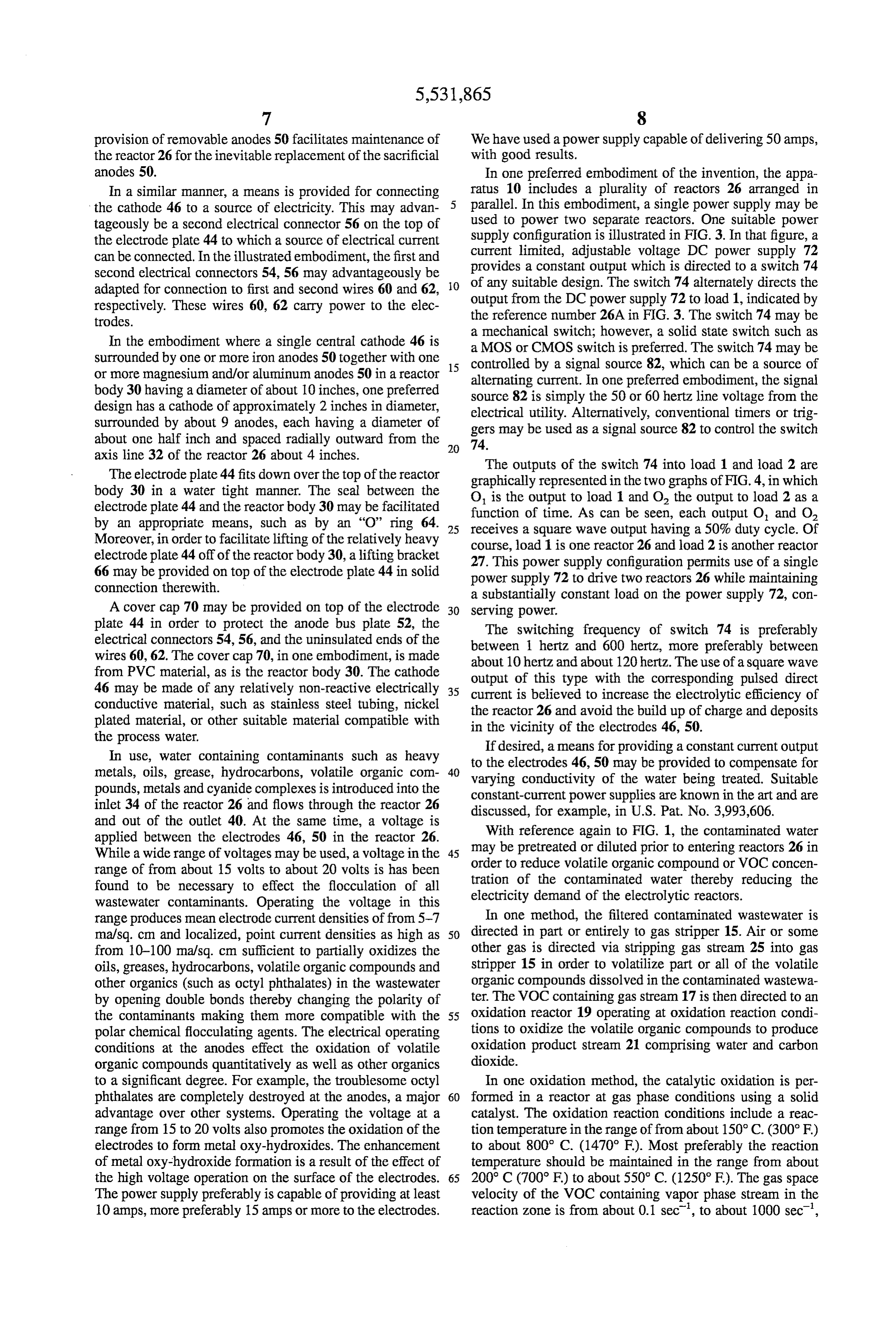
Page 8
provision of removable anodes 50 facilitates maintenance of We have used a power supply capable of delivering 50 amps, the reactor 26 for the inevitable replacement of the sacrificial with good results.
anodes 50. In one preferred embodiment of the invention, the appa In a similar manner, a means is provided for connecting ratus 10 includes a plurality of reactors 26 arranged in the cathode 46 to a source of electricity. This may advan 5 parallel. In this embodiment, a single power supply may be tageously be a second electrical connector 56 on the top of used to power two separate reactors. One suitable power the electrode plate 44 to which a source of electrical current supply configuration is illustrated in FIG. 3. In that figure, a can be connected. In the illustrated embodiment, the first and current limited, adjustable voltage DC power supply 72 second electrical connectors 54, 56 may advantageously be provides a constant output which is directed to a switch 74 adapted for connection to first and second wires 60 and 62, O of any suitable design. The switch 74 alternately directs the respectively. These wires 60, 62 carry power to the elec output from the DC power supply 72 to load 1, indicated by trodes. the reference number 26A in FIG. 3. The switch 74 may be a mechanical switch; however, a solid state switch such as
In the embodiment where a single central cathode 46 is a MOS or CMOS switch is preferred. The switch 74 may be surrounded by one or more iron anodes 50 together with one 15 controlled by a signal source 82, which can be a source of or more magnesium and/or aluminum anodes 50 in a reactor alternating current. In one preferred embodiment, the signal body 30 having a diameter of about 10 inches, one preferred source 82 is simply the 50 or 60 hertz line voltage from the design has a cathode of approximately 2 inches in diameter, electrical utility. Alternatively, conventional timers or trig surrounded by about 9 anodes, each having a diameter of gers may be used as a signal source 82 to control the switch about one half inch and spaced radially outward from the 20 74.
axis line 32 of the reactor 26 about 4 inches.
The outputs of the switch 74 into load 1 and load 2 are
The electrode plate 44 fits down over the top of the reactor graphically represented in the two graphs of FIG.4, in which body 30 in a water tight manner. The seal between the O is the output to load 1 and O, the output to load 2 as a electrode plate 44 and the reactor body 30 may be facilitated by an appropriate means, such as by an "O' ring 64. 25 receives aofsquare function time. As can be seen, each output O and O wave output having a 50% duty cycle. Of
Moreover, in order to facilitate lifting of the relatively heavy course, load 1 is one reactor 26 and load 2 is another reactor electrode plate 44 off of the reactor body 30, a lifting bracket 27. This power supply configuration permits use of a single 66 may be provided on top of the electrode plate 44 in solid power supply 72 to drive two reactors 26 while maintaining connection therewith.
a substantially constant load on the power supply 72, con
A cover cap 70 may be provided on top of the electrode 30 Serving power.
plate 44 in order to protect the anode bus plate 52, the The switching frequency of switch 74 is preferably electrical connectors 54, 56, and the uninsulated ends of the between 1 hertz and 600 hertz, more preferably between wires 60, 62. The cover cap 70, in one embodiment, is made about 10 hertz and about 120 hertz. The use of a square wave from PVC material, as is the reactor body 30. The cathode 46 may be made of any relatively non-reactive electrically 35 output of this type with the corresponding pulsed direct current is believed to increase the electrolytic efficiency of conductive material, such as stainless steel tubing, nickel the reactor 26 and avoid the build up of charge and deposits plated material, or other suitable material compatible with in the vicinity of the electrodes 46, 50. the process water.
In use, water containing contaminants such as heavy If desired, a means for providing a constant current output metals, oils, grease, hydrocarbons, volatile organic com 40 varyingto the electrodes 46, 50 may be provided to compensate for pounds, metals and cyanide complexes is introduced into the conductivity of the water being treated. Suitable constant-current power supplies are known in the art and are inlet 34 of the reactor 26 and flows through the reactor 26 discussed, for example, in U.S. Pat. No. 3,993,606. and out of the outlet 40. At the same time, a voltage is With reference again to FIG. 1, the contaminated water applied between the electrodes 46, 50 in the reactor 26.
While a wide range of voltages may be used, a voltage in the 45 may be pretreated or diluted prior to entering reactors 26 in range of from about 15 volts to about 20 volts is has been order to reduce volatile organic compound or VOC concen found to be necessary to effect the flocculation of all tration of the contaminated water thereby reducing the wastewater contaminants. Operating the voltage in this electricity demand of the electrolytic reactors. range produces mean electrode current densities of from 5-7 In one method, the filtered contaminated wastewater is ma/sq. cm and localized, point current densities as high as 50 directed in part or entirely to gas stripper 15. Air or some from 10-100 ma/sq. cm sufficient to partially oxidizes the other gas is directed via stripping gas stream 25 into gas oils, greases, hydrocarbons, volatile organic compounds and stripper 15 in order to volatilize part or all of the volatile other organics (such as octyl phthalates) in the wastewater organic compounds dissolved in the contaminated wastewa by opening double bonds thereby changing the polarity of ter. The VOC containing gas stream 17 is then directed to an the contaminants making them more compatible with the 55 oxidation reactor 19 operating at oxidation reaction condi polar chemical flocculating agents. The electrical operating tions to oxidize the volatile organic compounds to produce conditions at the anodes effect the oxidation of volatile oxidation product stream 21 comprising water and carbon organic compounds quantitatively as well as other organics dioxide.
to a significant degree. For example, the troublesome octyl In one oxidation method, the catalytic oxidation is per phthalates are completely destroyed at the anodes, a major 60 formed in a reactor at gas phase conditions using a solid advantage over other systems. Operating the voltage at a catalyst. The oxidation reaction conditions include a reac range from 15 to 20 volts also promotes the oxidation of the tion temperature in the range of from about 150° C. (300°F) electrodes to form metal oxy-hydroxides. The enhancement to about 800° C. (1470 F). Most preferably the reaction of metal oxy-hydroxide formation is a result of the effect of temperature should be maintained in the range from about the high voltage operation on the surface of the electrodes. 65 200° C (700°F) to about 550° C. (1250°F). The gas space The power supply preferably is capable of providing at least velocity of the VOC containing vapor phase stream in the 10 amps, more preferably 15 amps or more to the electrodes. reaction zone is from about 0.1 sect', to about 1000 sec',
Page 9
most preferably from about 5 sec to about 100 sec'. The Waste water leaving the reactors 26 may optionally pro reaction zone pressure preferably is in the operating range of ceed into a high speed mixer 83 where it is intimately from atmospheric to about 405 kPa (abs (44 psig), with a combined with additional materials that facilitate floc for most preferred operating pressure of from about atmospheric mation. These materials may include ferrous sulfate, a to about 150 Kpa (abs) 9 psig). The chemically oxidizable supplemental floc forming material that is useful for heavy compounds in the vapor stream are catalytically oxidized in metals and organic, and particularly useful for oil and grease the presence of the steam generated by heating the water and flocculation, as well as a combination of calcium chloride VOC containing gas stream 17. and sodium hydroxide, which together instantaneously form The solid catalyst used in the oxidation Zone may be calcium hydroxide, another effective floc former. The fer selected from any of the known commercially existing O rous sulfate may be provided from a ferrous sulfate reservoir oxidation catalyst compositions, or mixtures of known oxi 84, the calcium may be provided from a calcium chloride dation catalysts, that meet the required standards for stability reservoir 86, and the sodium hydroxide may be provided and that possess a high selectivity for oxidation of volatile from a sodium hydroxide reservoir 90. These reservoirs 84, organic and inorganic compounds. The active component of 86, 90 are provided, respectively, with second, third, and the oxidation catalysts is metal, preferably a nonprecious 15 fourth metering pumps, 92, 94, 96, respectively. These metal, supported on a solid carrier. The preferred solid metering pumps, 92,94, 96 meter their respective reagents carrier is alumina, however, any known carriers may be into the mixer 83 at a predetermined rate. For example, we used, for example, silica, silica-alumina, clay or like mate have found that ferrous sulfate, as FeSO47H20 dissolved in rials. The carrier may be in the form of spheres, pellets, or water, may advantageously be provided at the rate of about extradites. The amount of active metal on the catalyst is 20 500-2000 mg/liter (of the hydrate), and the calcium chloride preferably from about 5 to about 50 weight percent, based on and sodium hydroxide may advantageously be provided at the total catalyst weight. More preferably the metal compo the rate of 200-500 mg/liter in treating waste water from an ment comprises from about 15 to about 25 weight percent of industrial laundry. Of course, waste water from other the catalyst. A preferred oxidation catalyst composition sources may require different levels of these reagents. includes chromic oxide and alumina in the form of an Appropriate levels for these reagents may readily be deter extradite. This preferred catalyst and its method of prepa 25 mined by empirical measures.
ration are more thoroughly described in the U.S. Pat. No. In one preferred embodiment for the purification of dye 4.330,513 (Hunter et al.), which is incorporated herein by waters, iron and magnesium electrodes were employed in reference. the optimum ratio of six iron to three magnesium and only The use of gas stripper 15 is not needed when reactor 26 calcium chloride, sodium hydroxide and an organic floccu is operated at optimal voltage and current density levels so 30 lent were employed to produce colorless, clear water from as to ensure oxidation at the surface of the iron-magnesium, the dye house waste waters. The dye house waste waters, iron-aluminum or iron-aluminum-magnesium anode elec thus processed, were of such purity that they could be trode combinations. It should be appreciated, therefore, that discharged to the POTW or, better, recirculated to process a process and apparatus without gas stripper 15 would be 35 additional batches of fabric as many as five times. within the scope of the present invention. The output of the mixer 83 is directed into a floc tank 100. In an alternative oxidation method, the volatile organic The floc tank 100 is slowly stirred while the floc particles are compounds in clear contaminated water are partially or permitted to grow. Typically, the residence time of the waste totally oxidized using a photolyric oxidation alone or in water in the floc tank 100 should be from about 2 to about conjunction with an oxidizing agent such as hydrogen 40 20 minutes.
peroxide or ozone. One useful photolyric oxidation process In one preferred embodiment, formation of the floc is is the (Radinox) process manufactured by Electox Environ further facilitated by the addition of a chemical flocculent of mental, Inc. of San Mateo, Calif. The (Radinox) process is known type from a flocculent reservoir 102 through a fifth described in U.S. Pat. No. 4,849,115 which is incorporated metering pump 104 and into the water that has left the herein by reference. 45 reactor 26, preferably into the floc tank 100. Any of a The gas stripped contaminated wastewater stream 23 number of conventional flocculating agents may be used, produced by gas stripper 15 is directed to equalization tank including polymeric flocculent materials. These flocculating 16. Alternatively, clarified water product 125 can be mixed materials may be anionic, cationic, or nonionic, and can be with the contaminated wastewater to dilute the amount of selected based on the particular impurities being removed volatile organic compounds in the contaminated wastewater 50 from the waste water. We have used a non-ionic polymeric stream entering reactor 26. Diluting the VOC contaminated flocculating agent sold under the trademark PERCOL by wastewater improves the VOC oxidation efficiency of reac Allied Colloids, Suffolk, Va. with good results at the rate of tors 26. about 2-10 mg/liter in treating the effluent of an industrial The contaminated water from the first pump 20 enters one laundry.
or more reactors 26. In these reactors 26, electrolytic reac 55 After a predetermined residence time, sufficient to permit tions occur that facilitate the removal of a multitude of adequate formation of the floc, the floc-containing waste impurities from the water. A large number of metals are water is directed into clarifier 110 to separate the solids from converted to insoluble hydroxide forms. A hydrated ferrous the liquid. Clarifier 110 can be of any conventional design, hydroxide or ferric hydroxide is created from the sacrificial such as an inclined plate clarifier, an inverted 'v' element iron anodes, forming a floc. At the same time, a very 60 clarifier, or a conventional clarifier of other design. Suitable effective floc is formed electrolytically from the magnesium inverted "v" clarifiers are manufactured by Eimco Corpo or aluminum anodes. The use of such magnesium and/or ration, Salt Lake City, Utah under the trademark DELTA aluminum anodes for formation of a floc substantially STAK. Suitable inclined plate clarifiers are manufactured by improves the performance of the electrolytic reactor and Great Leaks Environmental Inc., Addison, Ill., and include facilitates much more complete removal of a wide range of 65 model designation ICP-4-880. Clarifier 110 will typically impurities from the waste water, including the oxidation of remove from 90 to 96% of the water from the solids. As volatile organic compounds and organics in the wastewater. solids build up in clarifier 110, they are removed by a sixth
Page 10
pump 112 and directed to a sludge tank 114. Periodically, the water (determined by infrared spectroscopy) from approxi sludge in the sludge tank 114 is pumped by means by a mately 250 ppm down to <20 ppm, cadmium from about 70 seventh pump 116 into a rotary vacuum filter 188 of con ppb down to about 4 ppb, and lead from about 400 ppb down ventional design. We have found that due to the nature of to about 2 ppb.
sludge formed by the process of the present invention, the As can readily be seen, reduction of impurities by an combination of a rotary vacuum filter 118 with the remain additional order of magnitude is accomplished by this step der of the purification apparatus 10 provides vastly superior of routing the clarifier effluent water through the rotary results. The rotary vacuum filter 118 is very resistant to vacuum filter when the rotary vacuum filter is not being used plugging, and rapidly removes water from the sludge to to process sludge. The clarifier effluent can be purified in this provide a relatively dry filter cake. 10 manner while the purification apparatus 10 is online, and the Atypical rotary vacuum filter 118 according to the present sludge tank 114 can be emptied while the purification invention has a cylindrical drum (which can be made of apparatus 10 is off line by running the sludge through the perforated steel covered with a polypropylene fabric) par rotary vacuum filter 118 during that time. Alternatively, the tially submerged in a filter submergence tank. The drum is apparatus 10 can be provided with two rotary vacuum filters, coated with a filter aid, which may be diatomaceous earth or 15 one for the clarified effluent water, and the other for sludge. other suitable material, such as the filter aids sold under the This would provide continuous on-line operation of the trademarks HARBORLITE by Harborlite Corp., Escondido, purification apparatus 10.
Calif., and CELITE by Mannsville Sales Corp., Lompoc, Solids removed by the sand separator 14 can be combined Calif. The filter as is typically coated onto the drum to a predetermined thickness, such as three inches. The drum 20 posal.solidifying agent in the blender 120 for landfill dis with rotates slowly through the submergence tank, as a vacuum is applied to the interior of the drum, drawing liquid into the The optimization of the operation of the process of the drum and depositing solids on top of the filter aid. The solids present invention can be further understood by reference to that collect on the filter aid are then shaved off of the drum the following example.
by a doctor blade, which slowly advances toward the drum 25 (e.g., at a rate of about 0.004 to 0.040 inches/minute). EXAMPLE The filter cake removed from the drum of the rotary One of the features of the invention is the discovery that vacuum filter 118 contains approximately 50% moisture. the heavy metals are rather completely bound-up in the This filter cake is directed into a blender 120 (such as a plow sacrificial anode oxy-hydroxide floc which is produced blender), where it is combined with a solidifying agent from 30 electrolytically in the flocculating reactors. The oxy-hydrox a hopper 122. The solidifying agent is a cementaceous ide of the heavy metal ions is very strongly absorbed to the material that solidifies the filter cake.
oxy-hydroxy floc formed from the binary-iron and mag
Suitable cementaceous solidifying agents are commer nesium sacrificial anodes. Hence, the very low solubilities of cially available. One suitable cementaceous material is an the heavy metal ions after exiting the system. Metal ion organophilic silicate cement available commercially from 35 concentrations below 10 ppb have been observed in the
Silicate Technology Corporation, Scottsdale, Ariz., under effluent waters produced by the process of this invention. the trademarks SOILSORB HM. SOILSORB HM is pre More importantly, it was discovered that one ratio of six iron ferred, but good results are also obtained with SOILSORB and three magnesium anode types in a typical reactor could HC. These organophilic cements are particularly advanta produce lower concentrations of contaminants per unit resi geous when substantial quantities of organic material are 40 dent time thus reducing reactor size, foot print and cost.
present in the filter cake, and they provide a nonleachable An additional feature of the invention was the discovery solid that can readily be disposed of in landfills. that oils and greases (miscellaneous hydrocarbon mixtures, In an alternative embodiment of the present invention, the even containing some vegetable fats and oils) were partially filter cake may be solidified by combining it with other 45 oxidized and, as more polar species, were more readily cementaceous materials, such as portland cement, or plastic occluded by the combination of highly polar inorganic and cement. When the cementaceous material is not lipophilic, organic flocculating agents. It was also observed, and, organic materials are preferably removed from the filter cake therefore, a significant part of this invention, that a minimum by roasting (e.g., heating to a temperature of 500 F to 900 flocculating reactor voltage need be impressed on the reactor F) in a suitable incinerator, such as a rotary kiln, prior to the 50 voltages to ensure this partial oxidation of the otherwise solidifying process. polar oils and greases.
The water leaving the clarifier 110 and the rotary vacuum The minimum voltage was determined to be in the range filter 118 contains very low levels of metals, oil, grease, and of 15–20 volts, imposed between the stainless steel cathode total suspended solids. This purified water can either be and the paired iron and magnesium anodes. This voltage directed to a municipal sewer, or in accordance with one 55 range, for the reactor configuration employed, translates into aspect of the invention, it can be recycled to the process in a current density of approximately 5 to 7 ma/.sq. cm. At which the water is generated. Thus, in a commercial laundry these preferred current densities, and at the pH range of 8-9 operation, the recycled water can be used, e.g., as makeup superoxide, hydroxide radical and nascent oxygen are all water for washing steps. produced in significant quantities so as to effect the partial To the extent necessary, the pH of the purified water can 60 oxidation of the hydrocarbons (oil and greases, volatile be adjusted by sulfuric acid or other pH adjusting material organic compounds, etc.) to some extent. Measurable reduc directed through the first valve 24 into the purified water. tions of volatile organic compounds have, in fact, been In still another embodiment of the present invention, the made. Furthermore, free oil pooling in the floc development water leaving the clarifier 110 is directed through a second tank downstream of the electrolytic reactors has been valve 124 and into the rotary vacuum filter 118 for further 65 observed and has been reversed and "pooling' eliminated by purification. By means of this optional step, we have been raising the current density to produce more of the oxidizing able to lower the levels of oil and grease in the clarified species cited above.
Page 11
EXAMPLE II relates to an electrolytic reactor of the type described oper A waste water purification apparatus 10 was provided ating with nine sacrificial anodes and one cathode. The ratio having a design capacity of 75 gallons per minute and of iron to magnesium anodes is changed progressively from operated at 50 gallons per minute. The pump 20 is directed two iron anodes and seven magnesium anodes to nine iron water from an industrial laundry at pH 10.5–12.5, adjusted anodes and Zero magnesium anodes. The data was obtained to pH 8-9, through six reactors 26. Each of the reactors 26 at a constant reactor voltage of 18 volts and with a total has a reactor body 30 formed of 10 inch diameter PVC with reactor current between the cathode electrode and the plu a volume of approximately 15.5 gallons each. The residence rality of anode electrodes of 10 amps of pulsed direct time of the water in each reactor operating at design capacity 10 Current.
FIG. 5 illustrates that minimum concentrations of is 1.5 minutes, but in this example the residence time in each approximately 7 ppb for the heavy metal of cupric copper reactor was approximately 1.9 minutes. Each reactor had are obtained when the ratio of sacrificial iron anodes to one central cathode and nine anodes, five of which were iron sacrificial magnesium anodes is 6:3. Reduction in heavy and four of which magnesium, arranged radially around the metal concentrations of this magnitude are important now central cathode in a circle of 4 inch radius. The anodes, 15 that the requirements for low heavy metal concentrations are which were alternately arranged around the cathode, were being enforced by the Environmental Protection Agency and approximately 72 inch in diameter and 48 inches long. The similar bodies for purification systems wishing to discharge cathode was approximately 2 inches in diameter, was their treated waters into estuaries and other waters where formed of No. 360 stainless steel tube and was approxi these requirements are most rigid and limiting. The optimal mately 48 inches long. 20 rationing of the types of anode electrodes have been found Square wave power was delivered to the reactors at 60 to be more effective than diluting VOC contaminated waste hertz and 15 volts from a 50 amp power supply. The current water in the manner discussed above.
Supplied to each reactor 26 was adjusted to approximately Data similar to that shown in FIG. 5 has been obtained for 20 amps. electrolytic reactors containing sacrificial anodes of iron and The electrolytically treated water leaving the six reactors 25 aluminum electrodes. Maximum heavy metal removal 26 entered the mixer 83, where it was combined with occurred at a ratio of five iron anodes and four aluminum FeSO,7H20 (1000 mg/liter), calcium chloride (about 300 anodes. The heavy metals of copper and zinc were reduced mg/liter) and sodium hydroxide (about 300 mg/liter). The to below 15 ppb and oil and greases to below 12 ppm. mixer 83 had a working capacity of about 26 gallons, and theCurrent densities were approximately 7 ma/sq. cm. For residence time of the water in the mixer 83 was about /2 30 industrial liquid streams containing levels of fats, oils and minute. The mixer 83 was connected to the floc tank 100, greases (FOG's) greater than 2,000 parts per million, the which has a volume of approximately 426 gallons. The optimum iron to aluminum ratio has been found to be 3:6, residence time of the liquid in the floc tank was about 8.5 while the optimum sacrificial iron anode to sacrificial mag minutes. nesium ratio for such streams has been found to be 5:4. Water leaving the floc tank 100 was directed into a 35 FOG's were reduced to below 15 ppm for the cited iron and specially modified EIMCO/DELTA-STACK clarifier which aluminum anode combination, while the iron and magne had a retention time of about 30 minutes. Sludge from the sium anode electrode pair of 5:4 reduced FOG's to less than clarifier was directed through a rotary vacuum filter. Purified 25 ppm at current densities of 7-10 ma/sq. cm. water leaves the clarifier exit to be recycled to the unit of to It has been found that optimal contaminant removal has be withdrawn as a clean treated water product. 40 been obtained with the electrolytic oxidation reactors of the The values of several contaminants in the water entering present invention when operated at current densities of at the process were compared with the values of the water least approximately 5 ma/sq. cm., preferably at current leaving the rotary vacuum filter, with the following results: densities ranging from 5-50 ma/sq. cm. and more preferably at current densities ranging from 5-10 ma/sq. cm. It is 45 desirable to maintain the operational current densities at as
CONTAMINANT BEFORE AFTER low a level as possible to minimize electrical power require Oil and Grease 2750 ppm 18 ppm enS.
Suspended Solids 3100 ppm 23 ppm It should be appreciated that the electrolytic oxidation Cadmium 2000 ppb 4 ppb vessel or reactor for use in the process of the present Lead 11000 ppb 2 ppb 50 invention can have other embodiments and be within the scope of the present invention. For example, an electrolytic
The levels all of these contaminants in the purified water are oxidation apparatus or reactor 201 similar to electrolytic well below typical Federal, State, and local water purity reactor 26 described above is illustrated in FIG. 6. Reactor Standards. 201 includes an elongate cylindrical vessel 202 having a In further developments of the present invention, it has 55 tubular side wall 203 made from any suitable electrically been found that an effective reduction of volatile organic insulating material such as polyvinyl chloride. Axially compounds and other contaminants, particularly heavy met extending side wall 203 has a first or upper extremity 203a als, can be achieved by optimizing the ratio of anode types and an opposite second or lower extremity 203b and serves used in parallel with a stainless steel cathode. Although the to form an internal chamber 206 of vessel 202. The vessel results of FIG. 5 relate to the heavy metal cupric copper, 60 202 further includes a hollow conical bottom wall portion similar results have been obtained for lead and chromium. 207 sealably joined to lower extremity 203b of the side wall As a result, it is expected that the results of FIG. 5 are and tapering radially inwardly at an angle of approximately equally applicable to other heavy metals. In this regard, the 22° to a lower apex 207a. Influent and outfluent means in removal of heavy metals such as lead, cadmium, chromium communication with internal chamber 206 are included and Zinc contaminating an industrial process stream would 65 within vessel 202 and include an influent inlet or inlet 211 be similarly effected by the ratio of iron and magnesium connected to upper extremity 203a of side wall 203 and an anodes provided in the reactor. The empirical data in FIG. 5 effluent outlet or outlet 212 connected to the lower apex
Page 12
207a of conical bottom wall portion 207. Tubular inlet and rounding anode electrodes, on the diameter of the anode outlet couplings 211 and 212 have an internal diameter of electrodes and the mean conductivity of the contaminated approximately 2.5 inch and are preferably threaded so as to Water stream to be treated.
be of a quick-connect type. Vessel 202 is provided with a cap The currently provided electrode replacement process 213 sealably joined to upper extremity 203a of side wall involves the physical disassembly of the electrolytic reactor portion 203. Conical bottom wall portion 207 and cap 213 on a periodic basis, which can be as often as once every six are each formed from any suitable material such as polyvi to eight weeks of operation. The "corroded” anode elec nyl chloride. As so constructed, side wall portion 203 has an trodes are replaced one by one and any residual anode internal length ranging from 40 to 66 inches and an internal sections or their conductive core materials are removed from transverse dimension or diameter ranging from 8 to 16 10 the bottom of the internal chamber of the reactor to ensure inches. unimpeded flow of the treated water downstream of the An electrode assembly 221 substantially similar to that reactO.
included within oxidation reactor 26 is carried by vessel 202 It has also been learned that the electrodes prepared for and, more specifically, includes at least one elongate cathode use in the reactor slowly but significantly corrode on expo electrode 222 made from any suitable inert material such as 15 sure to moist air after machining and cleaning at the factory. stainless steel and extending axially down the center of This pre-installation corrosion can significantly affect the internal chamber 206. The centrally-disposed cylindrical initial solution rate of the sacrificial anode electrodes when cathode electrode 222 can have a length ranging from 36 to emplaced in the reactor and when electrical energy is first 60 inches and an external diameter ranging from 9 to 18 applied to the electrodes.
inches. Electrode assembly 221 further includes a plurality 20 Reactor 201 permits the electrode assembly 221 to be of elongate sacrificial anode electrodes 223 within chamber encapsulated and hermetically sealed in an inert gaseous 206 aligned parallel with cathode electrode 222 and circum atmosphere such as dry nitrogen at the factory and kept ferentially disposed about the cathode electrode at approxi sealed until just moments before installation. In this regard, mately equal angular intervals. For simplicity, only some of the freshly prepared electrode assembly 221 will be desic the anode electrodes are shown in the schematic illustration 25 cated, flushed and sealed with the inert, dry gas before of FIG. 6. Each anode electrode 223 is similarly sized and storage and shipping to the customer. The controlled atmo can have a length ranging from 36 to 60 inches and an outer sphere around the electrode assembly during storage and diameter ranging from 0.5 to 2.0 inch. The dimensions of the shipping serves to minimize corrosion to the electrode electrodes are dependent in part upon the flow rate through assembly prior to installation and use. reactor 201. For example, anode electrodes 223 may mea 30 Immediately prior to installation, caps 236 and 237 are sure approximately 30 inches in length for lower flow rates removed from the inlet and outlet of vessel 202 to permit and approximately 50 inches in length for higher flow rates reactor 20 to be coupled to the treatment system and used such as 12.5 gpm. in the manner discussed above for removing contaminants As discussed above, the composition of anode electrodes from a flow of wastewater. The relative equal distance 223 can vary. Favorable results have been found with a 35 between anode electrodes 223 minimizes uneven dissolution combination of iron and magnesium or iron and aluminum of the anode electrodes. The conical bottom wall portion 207 electrodes. A combination of iron, magnesium and alumi of vessel 202 avoids hang-ups of floc, sand or other par num electrodes is also possible. The ratio of iron to mag ticulate matter at the outlet of the vessel and thus facilitates nesium and/or aluminum anode electrodes has been found to continuous flow from chamber 206 of the vessel. be important in maximized contaminant removal as dis 40 Although the present invention has been described in the cussed above. context of the certain preferred embodiments, it should be Means is provided for securing and carrying electrode recognized that the invention has broad applicability. assembly 221 and includes cap 213. More particularly, a Accordingly, it is not intended that the scope of the inven flange assembly 226 similar to that provided for reactor 26 tions be limited to the particularly disclosed embodiments. is included within reactor 201. Flange assembly includes an 45 Rather, the scope of the invention should be determined by electrode plate 227 made from any suitable insulating mate reference to the following claims. rial. An anode bus plate 228 is secured to the electrode plate What is claimed is:
and is electrically connected to each of the anode electrodes 1. A method for removing contaminants from a flow of 223. Connector means including electrical connector 231 is wastewater using a purification apparatus which includes included within reactor 201 and is electrically connected to 50 conduit means and an electrolytic oxidation vessel provided cathode electrode 222 by a first means or wire (not shown) with a chamber and inlet and outlet fittings in communica and to anode bus plate 228 by a second means or wire (not tion with the chamber, the inlet and outlet fittings being shown). Electrical connector 231 permits the application of coupled to the conduit means, the vessel having at least one a voltage across and between the cathode electrode and the elongate cathodic electrode and a plurality of elongate plurality of sacrificial anode electrodes as discussed above 55 sacrificial anodic electrodes aligned in parallel with the with respect to reactor 26. cathodic electrode in the chamber, comprising the steps of First and second hermetically sealing means which can directing the flow of wastewater through the conduit means include first or inlet cap 236 and second or outlet cap 237 are and through the chamber of the electrolytic oxidation vessel respectively mounted to inlet 211 and outlet 212. Caps 236 in a direction parallel with the cathodic and anodic elec and 237 are removably mounted to the respective inlet and 60 trodes so that the flow of wastewater engages the cathodic outlet. and anodic electrodes, applying a voltage across the The hermetically sealed reactor 201 facilitates the cathodic electrode and the sacrificial anodic electrodes to replacement of the sacrificial anode electrodes 223. As can create a current having a density ranging from approxi be appreciated, the useful operational period of the anode mately 5-50 ma/sq. cm. so as to release ions from the anodic electrodes depends on the electrical parameters under which 65 electrodes which oxidize and render insoluble contaminants the electrolytic cells of reactor 201 are operated, on the in the flow of wastewater and create insoluble contaminants spacing between the central cathode electrode and the sur and substantially cleansed water, separating the insoluble
Page 13
contaminants from the substantially cleansed water, discon 16. The method of claim 1 further comprising the step of necting the inlet and outlet fittings of the vessel from the adding a polymeric flocculent to the insoluble contaminants conduit means, selecting another vessel similar to said first and substantially cleansed water. named vessel and having inlet and outlet fittings which were 17. The method of claim 1 wherein the flow of wastewater hermetically sealed prior to use so as to inhibit corrosion of includes at least 10 ppm lead and wherein the applying step the anodic electrodes, unsealing the inlet and outlet fittings includes creating substantially cleansed water containing no of said another vessel, coupling the inlet and outlet fittings more than 500 ppb lead.
of said another vessel to the conduit means and repeating 18. The method of claim 1 wherein the flow of wastewater said directing, applying and separating steps. includes at least 1 ppm cadmium and wherein the applying 2. The method of claim 1 wherein the applying step 10 step includes creating substantially cleansed water contain includes permitting a floc containing insoluble contaminants ing no more than 100 ppb cadmium. to form in the chamber of the electrolytic oxidation vessel. 19. The method of claim 1 wherein the flow of wastewater 3. The method of claim 2 wherein the separating step includes coalescing the floc into a sludge. includes at least 1000 ppm oil and grease and wherein the 4. The method of claim 3 wherein the separating step applying step includes creating substantially cleansed water includes directing the sludge through a filter to generate a 15 containing no more than 100 ppm oil and grease. sludge cake. 20. The method of claim 1 wherein the flow of wastewater 5. The method of claim 4 wherein the directing step is generated in an industrial process, the method further includes directing the sludge through a filter selected from comprising the step of directing the substantially cleansed the group consisting of rotary vacuum filters and plate and water into the industrial process. frame filters. 20 21. The method of claim 1 wherein the directing step 6. The method of claim 4 wherein the separating step includes diluting the flow of wastewater with substantially includes combining the sludge cake with a cementaceous cleansed water.
material to form a non-leachable solid. 22. A modular electrolytic oxidation reactor for use in a 7. The method of claim 3 wherein the separating step treatment system which removes contaminants from a flow includes directing the sludge through a clarifier to generate 25 of wastewater comprising a vessel having an internal cham a sludge cake. ber and inlet and outlet fittings in communication with the 8. The method of claim 2 wherein the permitting step chamber adapted to permit the flow of wastewater to enter includes adding a chemical flocculating agent to the and exit the chamber, an electrode assembly carried by the insoluble contaminants and substantially cleansed water. vessel within the chamber including at least one elongate 9. The method of claim 2 wherein the permitting step 30 cathodic electrode and a plurality of elongate sacrificial includes adding ferrous sulfate to the insoluble contaminants anodic electrodes, connector means carried by the vessel and and Substantially cleansed water. electrically coupled to the cathodic electrode and the sacri 10. The method of claim 2 wherein the permitting step ficial anodic electrodes of the electrode assembly for per includes providing calcium hydroxide to the insoluble con mitting a voltage to be applied across the cathodic electrode taminants and substantially cleansed water. 35 and the sacrificial anodic electrodes and first and second 11. The method of claim 10 wherein the applying step removable seal means mounted respectively on the inlet and includes injecting sodium hydroxide and calcium chloride outlet fittings for hermetically sealing the inlet and outlet into the flow of wastewater. fittings prior to installation in the treatment system so as to 12. The method of claim 1 wherein the contaminants in inhibit corrosion of the sacrificial anodic electrodes prior to the flow of wastewater include hydrocarbons, oil, grease and 40 installation of the modular reactor whereby the first and volatile organic compounds and wherein the applying step second seal means can be removed to permit the modular includes creating partially oxidized hydrocarbons, oil and reactor to be coupled to the treatment system and whereby grease and oxidized volatile organic compounds from the the modular reactor facilitates replacement of the sacrificial flow of wastewater. anodic electrodes.
13. The method of claim 1 wherein the contaminants in 45 23. A reactor as in claim 22 wherein the plurality of the flow of wastewater include volatile organic compounds, elongate sacrificial anodic electrodes include a plurality of the method further comprising the step of pretreating the anodic electrodes made from iron and a plurality of anodic wastewater in a gas stripper to volatilize at least some electrodes made from magnesium.
volatile organic compounds and create a VOC containing 24. A reactor as in claim 23 wherein the ratio of iron gas stream and a stripped flow of wastewater and oxidizing 50 anodic electrodes to magnesium anodic electrodes is the VOC containing gas stream in an oxidation reactor, the approximately 6:3.
stripped flow of wastewater being directed to the chamber of 25. A reactor as in claim 22 wherein the plurality of the electrolytic oxidation vessel. elongate sacrificial anodic electrodes include a plurality of 14. The method of claim 1 wherein the contaminants in anodic electrodes made from iron and a plurality of anodic the flow of wastewater include volatile organic compounds, 55 electrodes made from aluminum.
the method further comprising the step of destroying the 26. A reactor as in claim 25 wherein the ratio of iron volatile organic compounds by an oxidation process selected anodic electrodes to aluminum anodic electrodes is approxi from the group consisting of photolytic oxidation and cata mately 5:4.
lytic oxidation. - 27. A reactor as in claim 22 wherein the plurality of 15. The method of claim 1 for use with an additional 60 elongate sacrificial anodic electrodes include a plurality of electrolytic oxidation vessel similar to the first named elec anodic electrodes made from iron, a plurality of anodic trolytic oxidation vessel wherein the directing step includes electrodes made from magnesium and a plurality of anodic directing a portion of the flow of wastewater into the electrodes made from aluminum.
chamber of the additional electrolytic oxidation vessel and 28. A modular electrolytic oxidation reactor for use in a wherein the applying step includes alternately directing 65 treatment system which removes contaminants from a flow voltage between the first named electrolytic oxidation vessel of wastewater comprising a vessel having an internal cham and the additional electrolytic oxidation vessel. ber and inlet and outlet fittings in communication with the
Page 14
chamber adapted to permit the flow of wastewater to enter reactor to be coupled to the treatment system and whereby and exit the chamber, an electrode assembly carried by the the modular reactor facilitates replacement of the sacrificial vessel within the chamber including at least one elongate anodic electrodes.
cathodic electrode and a plurality of elongate sacrificial 29. A reactor as in claim 28 wherein the vessel further anodic electrodes, connector means carried by the vessel and includes a cap joined to the upper extremity of the side wall, electrically coupled to the cathodic electrode and the sacri the electrode assembly being carried by the cap. ficial anodic electrodes of the electrode assembly for per 30. A reactor as in claim 22 wherein the cathodic electrode mitting a voltage to be applied across the cathodic electrode and the sacrificial anodic electrodes and first and second extends along an axis and the sacrificial anodic electrodes removable seal means mounted respectively on the inlet and 10 extends in directions parallel to the axis. outlet fittings for hermetically sealing the inlet and outlet 31. A reactor as in claim 22 together with an inert gas fittings prior to installation of the modular reactor in the disposed within the vessel for minimizing corrosion to the treatment system so as to inhibit corrosion of the sacrificial sacrificial anodic electrodes.
anodic electrodes prior to installation whereby the first and second seal means can be removed to permit the modular
Provenance
- Collection
- Cited prior art
- Original PDF
- patentimages.storage.googleapis.com →
- Filed
- 1995-02-28
- Pages
- 14
- Method
- pdftotext (the PDF's own text layer) + pdftoppm 300dpi page scans
- Source
- Google Patents bibliographic record
- Granted
- 1996-07-02
- Inventors
- Leland G. Cole
- Transcribed from
- patentimages.storage.googleapis.com →