patent · US4307711
Sun tracking solar energy collector system
29 December 1981
Page 1 — bibliographic record
United States Patent (19) 11) 4,307,711 Doundoulakis 45) Dec. 29, 1985
54 SUNTRACKINGSOLAR ENERGY ing a plurality of light focusing elements disposed side COLLECTOR SYSTEM by side in the form of a surface array, providing a linear array of foci; and a metallic heat exchanger tube having 76 Inventor: George J. Doundoulakis, 2498 externally a high absorbtivity, low reflectivity coating Kayron La., North Bellmore L.I., containing a working fluid such as water, air, hydrogen
or helium, to which a substantial portion of the energy 21 Appl. No.: 124,517 in the focused light is imparted. The system includes an 22 Filed: Feb. 25, 1980 insulator tube external to the heat exchanger and pro viding small apertures covered by glass to allow the 51) int. Cl.................................................. F24, 3/02 light focused by each focusing element to enter the 52 U.S.C. ..................................... 126/442; 126/440 interior of the insulator tube, where the light may im 58 Field of Search ............... 126/424, 425, 440, 442, pinge directly on the heat exchanger tube or on solar 126/443, 441,446, 450, 417 cells attached to the heat exchanger and facing the 56 References Cited apertures, for conversion of a portion of the focused
portion of the energy focused through the apertures 1,599,481 9/1926 Marcuse .............................. 26/440 ends up as heat through the heat exchanger tube into the 1,683,266 9/1928 Shipman .............................. 26/440 working fluid, capable of raising its temperature to a 3,203,167 8/1965 Green .......... ... 26/440 3,869,199 3/1975 Cummings .. ... 126/440 desirable temperature. A highly reflective internal sur 4,022,186 5/1977 Northrup ... ... 126/440 face of the insulator tube serves to reflect toward the 4,069,812 1/1978 O'Neill ................ ... 126/440 heat exchanger radiation reaching it from the solar cells 4,119,085 i0/1978 Knowles et al. ... ... 126/443
and the heat exchanger, so that with the reflective inter 4,187,123 2/1980 Diggs .................. nal surface being much larger than the surface covered 4,188,941 2/1980 Hopkins .. ... 26/440 4,205,661 6/1980 Chapman ... ... 126/440 by the apertures a very small percentage of the radiated 4,238,246 12/1980 Genequand ......................... 126/440 energy is allowed to escape to space through the aper tures. A vacuum maintained between the heat ex
Primary Examiner-Daniel J. O'Connor changer and the external insulator tube serves to mini Attorney, Agent, or Firm-Constantine A. Michalos; mize conductive losses.
Peter C. Michalos
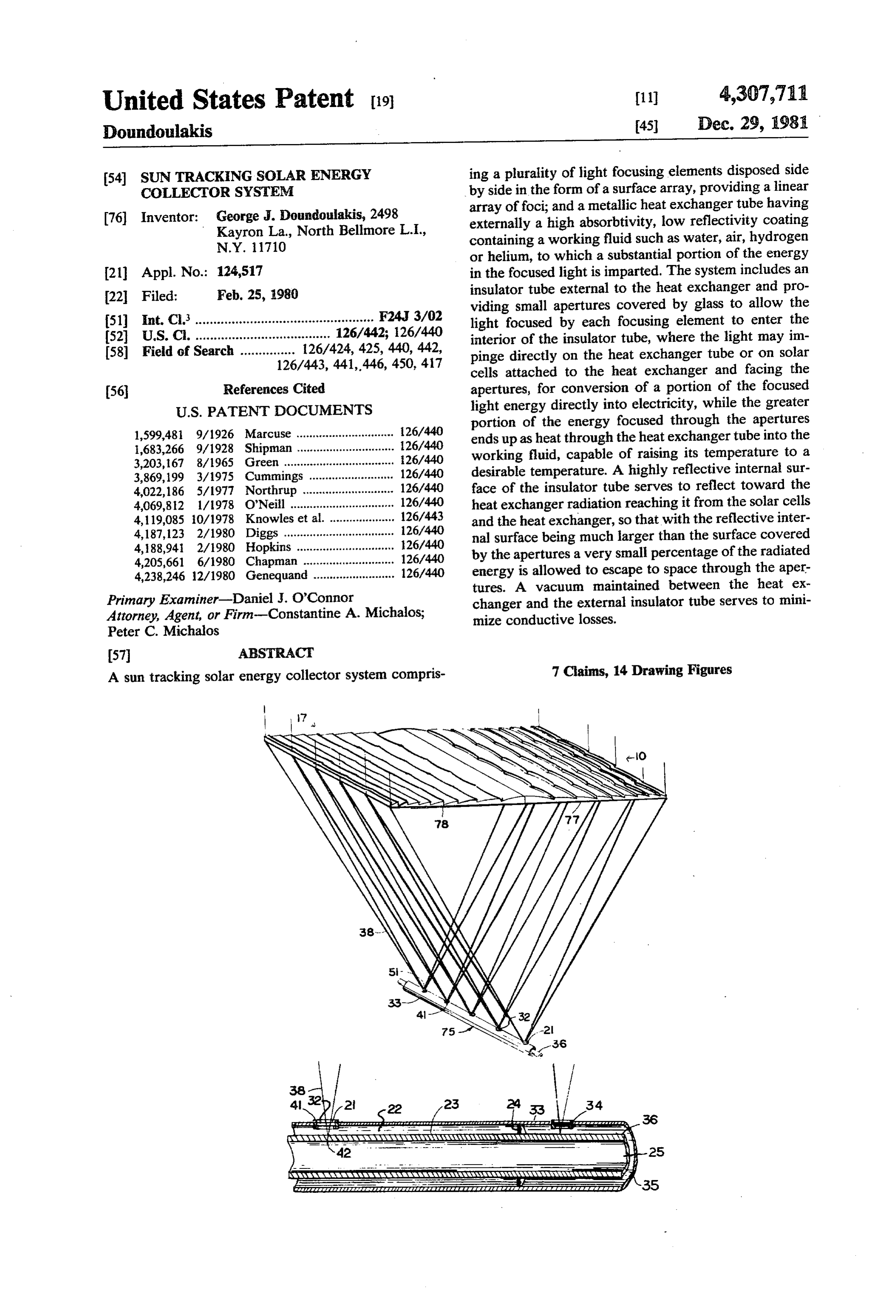
A sun tracking solar energy collector system compris 7 Claims, 14 Drawing Figures
Rese sy www.
Page 2
Drawing sheet — no readable text.
Page 3
Drawing sheet — no readable text.
Page 4
Drawing sheet — no readable text.
Page 5
Drawing sheet — no readable text.
Page 6
XXX 23S
YAYV "V. XVZV
M v. tax Avezzi
AAAAAAYAAAAAAAYAAAAAAAAAAAAAYANAVN W
AESESs Asses amate
ZZZZZZZZZZZZZZZZZZZZZZZZZZZZZZ 77777777.777777AAAZZ 77A77 AA 7777,777.777A-7,
ZZZZZZZZZzarzzzzzzzzzzzzzzz
zarzzzzzzzzzzzzzzzz asarage age as facifistured dealedaddadded as
Kassavvavasawaxxxxv,
seawasaaaaaaaaaaaaaaaaawaaaaaaaaaaaasa-AAR essarasasawa YaYaw s assasaesaaaaa
a 7A. Azazz Az Zazzazzazz777,777/7272/
Page 7
Drawing sheet — no readable text.
Page 8
Drawing sheet — no readable text.
Page 9
Drawing sheet — no readable text.
Page 10
Drawing sheet — no readable text.
Page 11
Difficulties also exist in keeping a vacuum between an
SUNTRACKING SOLAR ENERGY COLLECTOR inner heat exchanger and an outer shield when a slot SYSTEM along the outer shield must remain transparent for the solar radiation to enter. Attempting to cover the slot
BACKGROUND OF THE INVENTION 5 with a transparent substance such as glass while keeping 1. Field of the Invention the glass sealed surrounding a metallic inner heat ex This invention relates in general to solar energy col changer, and at a wide range of temperatures, while lectors for capturing Solar energy falling over a surface maintaining a vacuum between the glass shield and the area, in terms of heat, raising the temperature of a fluid, 10 metallic heat exchanger.
and particularly to a sun tracking solar energy collector A third type of solar collecting devices may be re system means for increasing the temperature of the fluid ferred to as superimposed focusing collectors providing and the efficiency of solar energy capture per unit of focusing of a multiplicity of sun tracking reflectors area using focussing means, solar tracking means, solar commonly referred to as heliostats, on to same area of a cells and an internal type heat exchanger means. heat exchanger, where substantially high temperature 2. Description of the Prior Art and of Optimizing 15 can be sustained.
Factors The main advantage of the superimproved focussing There has been a number of devices for capturing and solar collectors in that they can gather substantial utilizing heat energy from the sunlight. One type of amounts of solar energy per day, measured in megawatt such devices is the passive non tracking solar energy 20 hrs. per day. A drawback is that only a small portion of collecting panels providing in effect heat exchanging the heliostats is contributing efficiently to the common means between a highly light absorbing coating and heat exchanger at any time. Also because of the high water which is used for heating during the winter and temperatures involved at the heat exchanger radiation for faucet hot water the year around. Coatings with losses can be considerable. This type of system can be much higher absorbitivity than emissivity in the range acceptable in areas with high intensity of sun-light and of the solar spectrum have been developed. The princi 25 inexpensive land.
ple of what is commonly known as the "hot house ef While the solar energy now falling over the roofs of fect' whereby visible light is easily transmitted through houses and industrial buildings is almost entirely being a transparent sheet, such as glass or acrylic plastic, wasted, as the price of oil will increase, the value of this imparting heat energy onto the absorbing surface at energy will also increase. Solar energy collectors which relatively low temperatures, so that the surface then can 30 may appear to provide a benefit in terms of hot water to only radiate in the infrared spectrum which is only a homeowner today may be determined to be wasteful a partially transmitted through said sheet, is beneficially few years from now when the cost of thermal energy used to retain the captured heat. The main drawbacks of will have substantially been increased. this type of solar collecting devices are: It should be noted that it is not only the number of 1. Lacking sun tracking the surface where the light 35 BTU's collected per year per unit area of surface that collecting device is installed is inefficiently used due to counts but the cosine law, capturing only a small portion of its are counted.also The the temperature at which these BTU's higher the temperature of the working potential energy capture. fluid the higher the value of the energy because the heat 2. The temperature at which the water can be raised in the hotter working fluid can be converted into more is relatively low (about 145 F.). While low temperature valuable forms of energy is useful for heating and for hot water, it cannot be used efficiency. From Carnot'ssuch as electricity, at a higher cycle considerations the max efficiently for the generation of electricity or to provide imum thermal efficiency possible in a heat engine is for air-conditioning through an absorption type refrig eration unit. inc= 1 - TL/TH (1) 3. Despite the "hot house effect" a considerable 45 amount of the captured heat is being re-radiated into Where TH and TL are the high and low temperatures space, or lost through conduction to the outside air.
4. Defining a price quality factor as the yearly dollar between which the engine operates, expressed as abso benefit derived by the device, divided by the overall perature, which isIfusually lute temperatures. TL is taken to be the ambient ten the case, the efficiency in cost of the installation, it has been found that such factor 50 deteriorates as TH is approaching TL. While ne is unat is relatively low for this type of solar collectors. tainable in practical engines, the expression (1-TL/TH) A second type of solar collecting devices may be referred to as line focus solar energy collecting devices turns out to be a controlling factor in the expression of which use optical means such as Fresnel lenses or cylin the efficiency of heat engines. It is for this reason that BTU's at relatively low temperature gases such as the drical paraboloidal reflectors to concentrate the sun 55 gases from the flute of oil burners and the exhaust of the light along a narrow focal line. This type may or may automobiles are allowed to excape because the tempera not include sun tracking means. ture of such gases is too low compared to the high The main benefit of the line focus solar collectors is that they provide sufficient light concentration to heat temperature of the system.
working fluid such as water to an intermediate tempera 60 system Another desirable feature of a solar energy collection ture such as between 200 and 300 F. Such water tem is the evenness of energy output during a normal peratures are capable of efficiently providing heat to an sunny day. The smaller the variation of energy output absorption type air conditioning system besides provid during the day the less energy storage will be required ing heating during the winter and hot water. by the system.
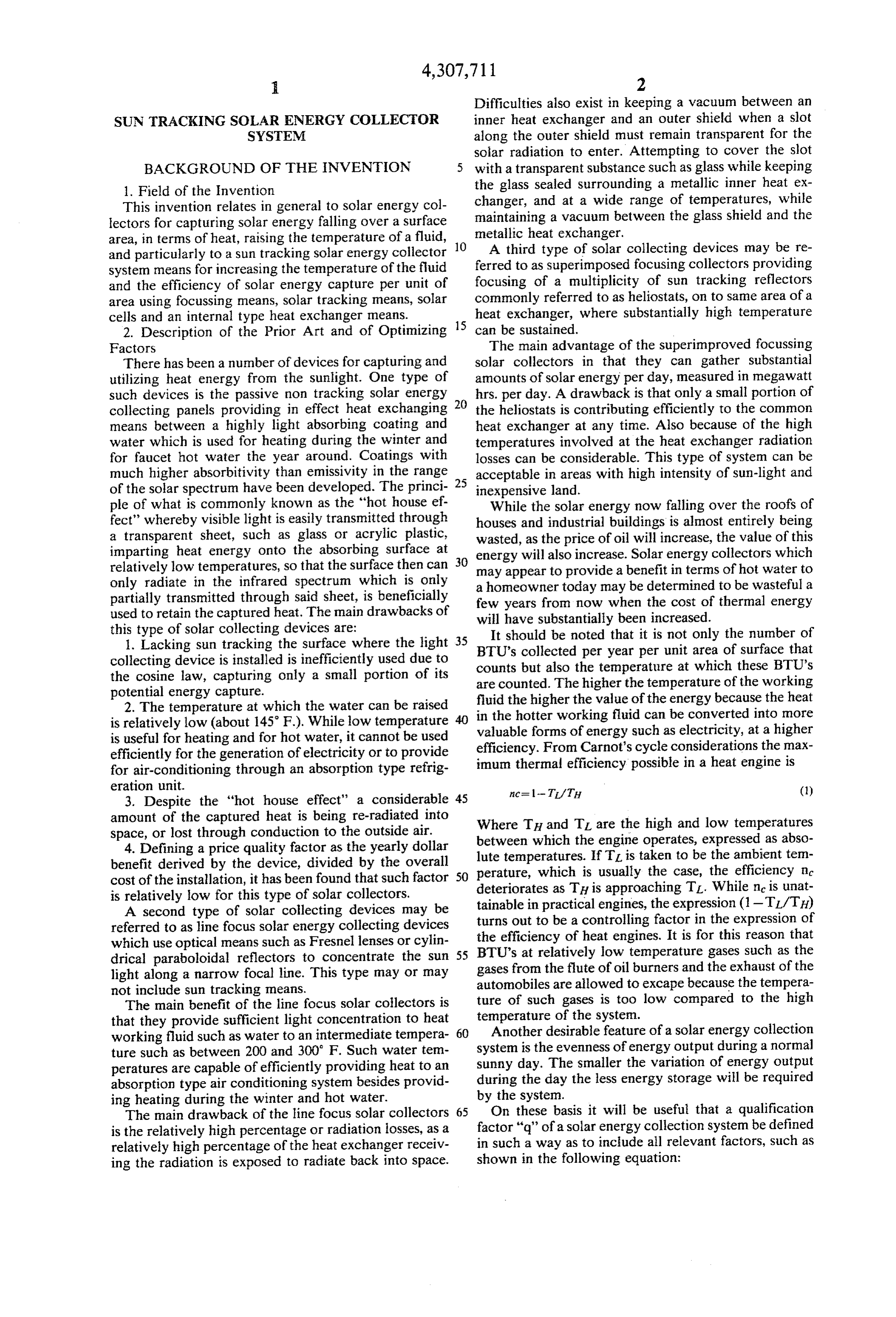
The main drawback of the line focus solar collectors 65 On these basis it will be useful that a qualification is the relatively high percentage or radiation losses, as a factor "q" of a solar energy collection system be defined relatively high percentage of the heat exchanger receiv in such a way as to include all relevant factors, such as ing the radiation is exposed to radiate back into space. shown in the following equation:
Page 12
tween inner and outer tubes. A single solar tracking platform supporting the focusing panels and the energy
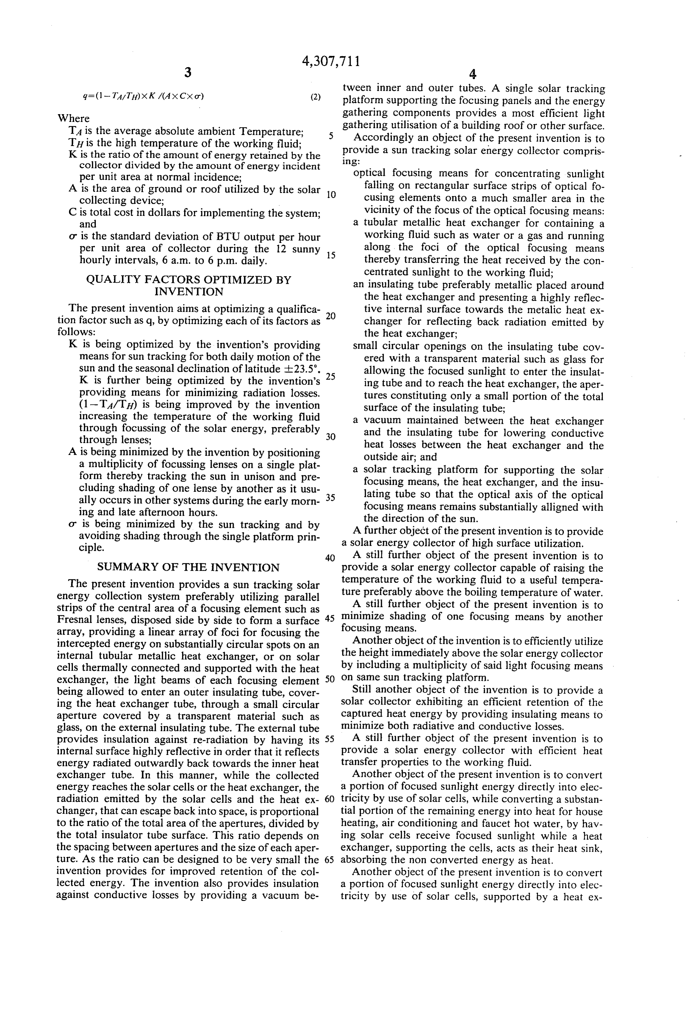
Where gathering components provides a most efficient light TA is the average absolute ambient Temperature; gathering utilisation of a building roof or other surface. TH is the high temperature of the working fluid; Accordingly an object of the present invention is to K is the ratio of the amount of energy retained by the provide a sun tracking solar energy collector compris
collector divided by the amount of energy incident optical focusing means for concentrating sunlight per unit area at normal incidence; falling on rectangular surface strips of optical fo A is the area of ground or roof utilized by the solar 10 collecting device; cusing elements onto a much smaller area in the C is total cost in dollars for implementing the system; vicinity of the focus of the optical focusing means: and a tubular metallic heat exchanger for containing a or is the standard deviation of BTU output per hour working fluid such as water or a gas and running per unit area of collector during the 12 sunny 15 along the foci of the optical focusing means hourly intervals, 6 a.m. to 6 p.m. daily. thereby transferring the heat received by the con centrated sunlight to the working fluid;
QUALITY FACTORS OPTIMIZED BY an insulating tube preferably metallic placed around INVENTION the heat exchanger and presenting a highly reflec The present invention aims at optimizing a qualifica tive internal surface towards the metalic heat ex tion factor such as q, by optimizing each of its factors as 20 changer for reflecting back radiation emitted by follows: the heat exchanger;
K is being optimized by the invention's providing small circular openings on the insulating tube cov means for sun tracking for both daily motion of the ered with a transparent material such as glass for sun and the seasonal declination of latitude -23.5'. allowing the focused sunlight to enter the insulat K is further being optimized by the invention's 25 ing tube and to reach the heat exchanger, the aper providing means for minimizing radiation losses. tures constituting only a small portion of the total (1-TA/TH) is being improved by the invention surface of the insulating tube; increasing the temperature of the working fluid a vacuum maintained between the heat exchanger through focussing of the solar energy, preferably 30 and the insulating tube for lowering conductive through lenses; heat losses between the heat exchanger and the A is being minimized by the invention by positioning outside air; and a multiplicity of focussing lenses on a single plat a solar tracking platform for supporting the solar form thereby tracking the sun in unison and pre focusing means, the heat exchanger, and the insu cluding shading of one lense by another as it usu 35 lating tube so that the optical axis of the optical ally occurs in other systems during the early morn focusing means remains substantially alligned with ing and late afternoon hours. the direction of the sun.
or is being minimized by the sun tracking and by A further object of the present invention is to provide avoiding shading through the single platform prin ciple. a solar energy collector of high surface utilization. 40 A still further object of the present invention is to
SUMMARY OF THE INVENTION provide a solar energy collector capable of raising the The present invention provides a sun tracking solar temperature of the working fluid to a useful tempera energy collection system preferably utilizing parallel ture preferably above the boiling temperature of water. strips of the central area of a focusing element such as minimize A still further object of the present invention is to Fresnal lenses, disposed side by side to form a surface 45 focusing means. shading of one focusing means by another array, providing a linear array of foci for focusing the intercepted energy on substantially circular spots on an Another object of the invention is to efficiently utilize internal tubular metallic heat exchanger, or on solar the height immediately above the solar energy collector cells thermally connected and supported with the heat by including a multiplicity of said light focusing means exchanger, the light beams of each focusing element 50 on same sun tracking platform.
being allowed to enter an outer insulating tube, cover Still another object of the invention is to provide a ing the heat exchanger tube, through a small circular solar collector exhibiting an efficient retention of the aperture covered by a transparent material such as captured heat energy by providing insulating means to glass, on the external insulating tube. The external tube minimize both radiative and conductive losses. provides insulation against re-radiation by having its 55 A still further object of the present invention is to internal surface highly reflective in order that it reflects provide a solar energy collector with efficient heat energy radiated outwardly back towards the inner heat transfer properties to the working fluid. exchanger tube. In this manner, while the collected Another object of the present invention is to convert energy reaches the solar cells or the heat exchanger, the a portion of focused sunlight energy directly into elec radiation emitted by the solar cells and the heat ex 60 tricity by use of solar cells, while converting a substan changer, that can escape back into space, is proportional tial portion of the remaining energy into heat for house to the ratio of the total area of the apertures, divided by heating, air conditioning and faucet hot water, by hav the total insulator tube surface. This ratio depends on ing solar cells receive focused sunlight while a heat the spacing between apertures and the size of each aper exchanger, supporting the cells, acts as their heat sink, ture. As the ratio can be designed to be very small the 65 absorbing the non converted energy as heat. invention provides for improved retention of the col Another object of the present invention is to convert lected energy. The invention also provides insulation a portion of focused sunlight energy directly into elec against conductive losses by providing a vacuum be tricity by use of solar cells, supported by a heat ex
Page 13
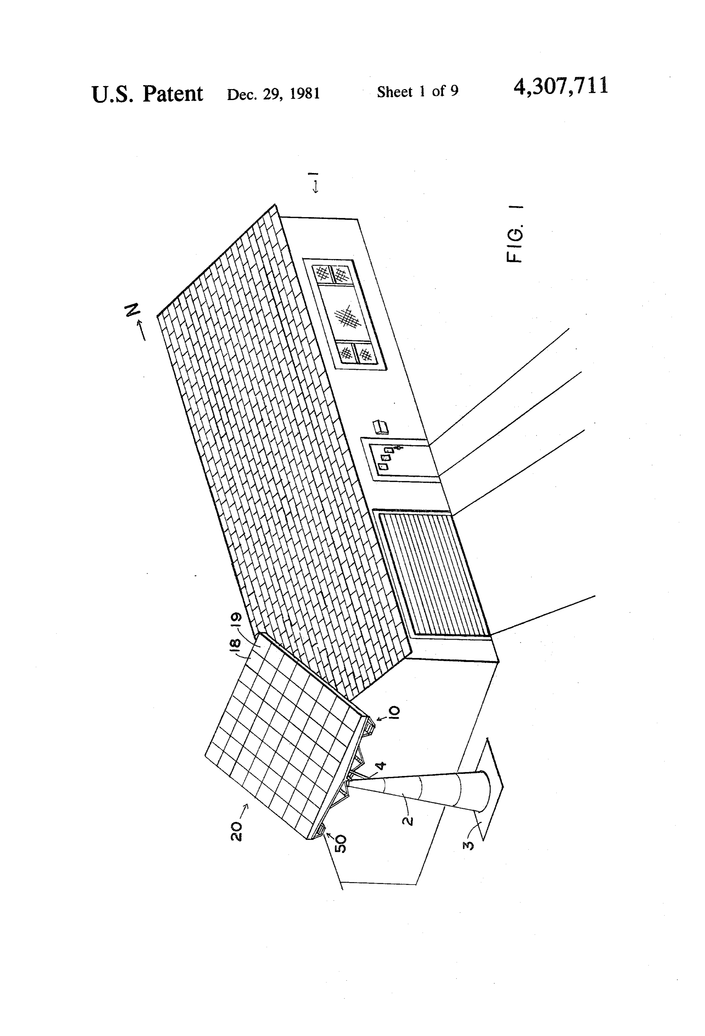
changer which is used as a heat sink, the cells being DESCRIPTION OF THE PREFERRED protected from mechanical damage by a tubular insula EMBODIMENTS tor external to the solar cells and the heat exchanger, Referring now to the drawings and particular to FIG. and also protected from moisture damage through a 5 1 and 8 a sun tracking solar energy collector system vacuum maintained inside the tubular insulator.
Another object of the present invention is to provide comprises light focusing means 10 rigidly supported by a solar collector with minimum variation of heat energy a sun tracking platform 20. The platform 20 is rotatably output during the 12 hours of daily sunshine. supported at the ends of a shaft 40 so that it can be continuously tracking the sun during its daily motion
Still another object of the present invention is to 10 provide a relatively light weight solar collector at rela from
The
East to West.
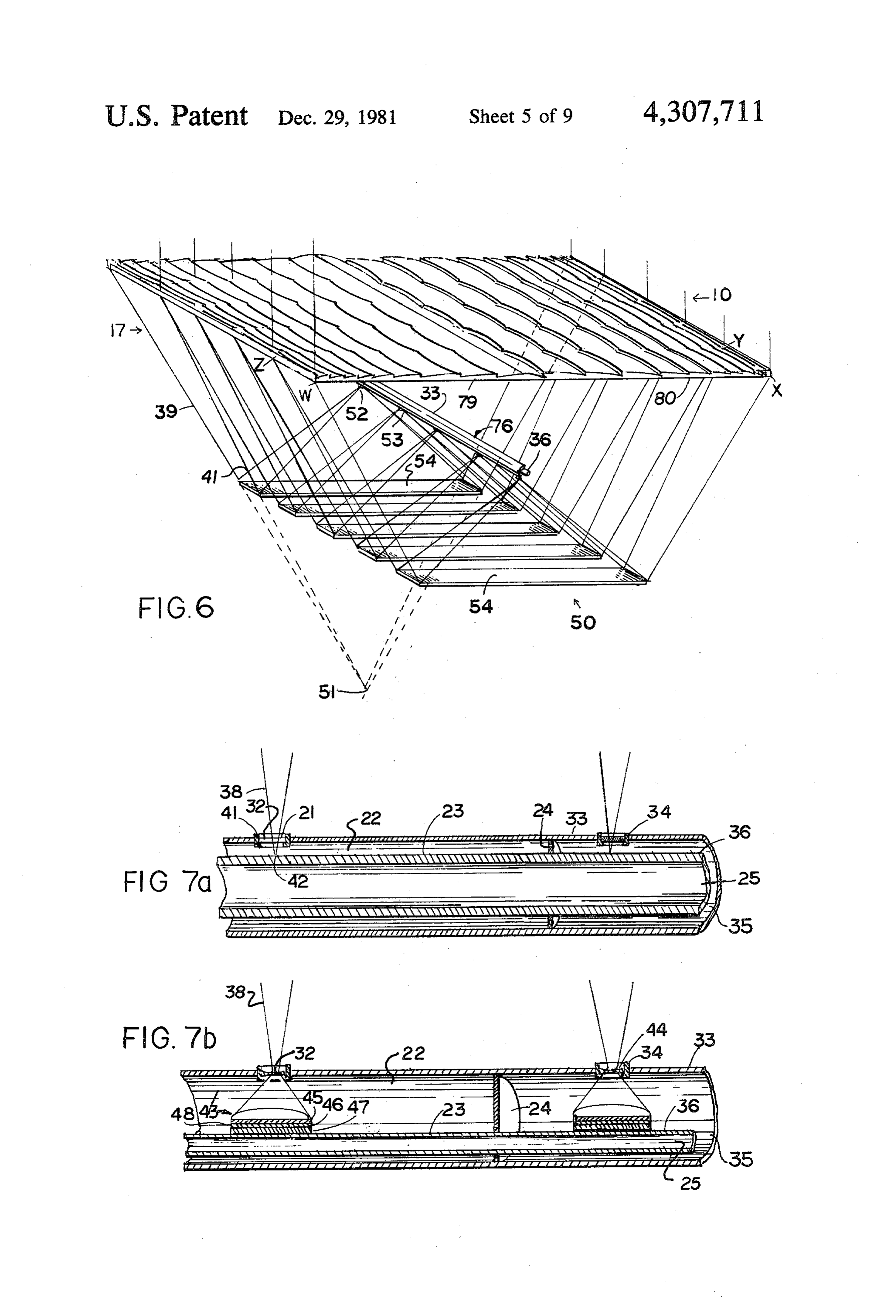
sunlight is being concentrated by the focusing tively low cost compared to the yearly monetary bene means 10, onto circular apertures 32 on a tubular insula fit. tor 33, allowing the light to reach an internal heat ex The various features of novelty which characterize changer tube 36, shown in detail in FIGS. 7a & 7b. The the invention are pointed out with partialarity in the 15 solar light may reach an aperture such as aperture 34 claims annexed to and forming a part of this disclosure. directly as shown in FIG. 5 and FIGS. 7a and 7b by sun For a better understanding of the invention, its operat ray 38, or through a reflection on mirrors, such as mir ing advantages and specific objects attained by its uses, rors 50, as shown in FIG. 6. In FIG. 6. In FIG. 6 the reference should behad to the accompanying drawings focus is effectively being displaced from a point 51 to a and descriptive matter in which there is illustrated a 20 new point 52 symmetric to the point 51 with respect to preferred embodiment of the invention. the reflecting mirror 54.
BRIEF DESCRIPTION OF THE DRAWINGS
As in the type of FIG. 5a heat exchanger 31 is sup ported internally of tube insulator 33 in the type where
In the drawings: mirrors 50 are used. The heat exchanger 31 receiving FIG. 1 is a side perspective view of a home installa 25 the rays reflected by the mirrors 50, lies much closer to tion of the invention, according to a preferred embodi the focusing means 10. The circular aperture, such as ment of the invention. apertures 32 allowing the concentrated light to reach FIGS. 2a, 2b are plan view and side view, respec the internal heat exchanger 36, are facing downwards, tively, of a reflective type focusing element means 30 towards
the mirrors 50, and therefore are not shown in showing the derivation of the portions of reflector
WXYZ actually used in conjunction with heat ex rectTherefore, focusing
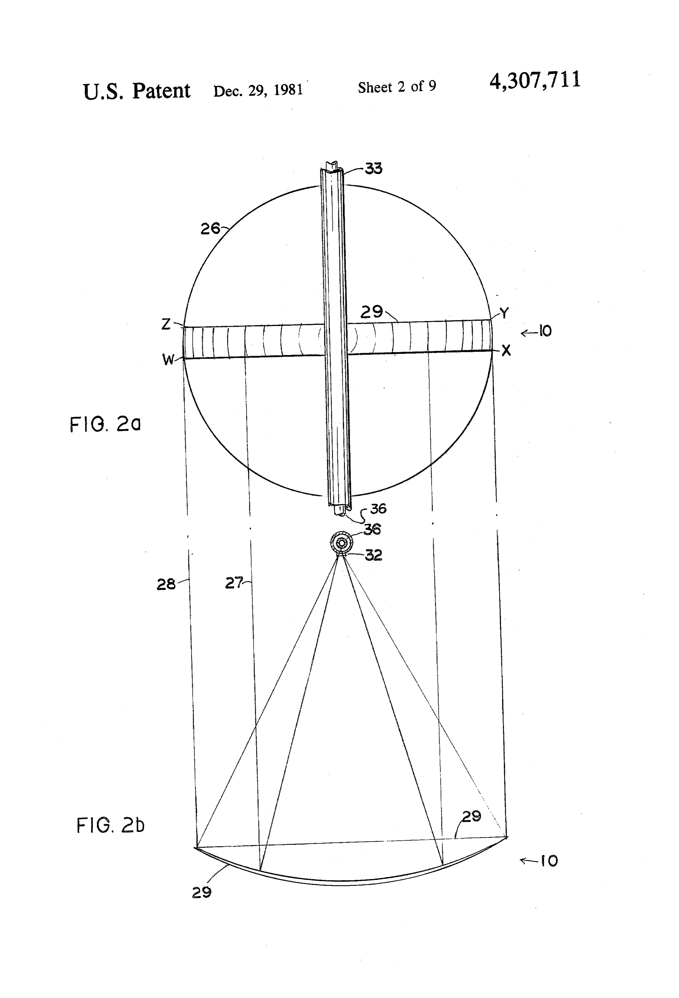
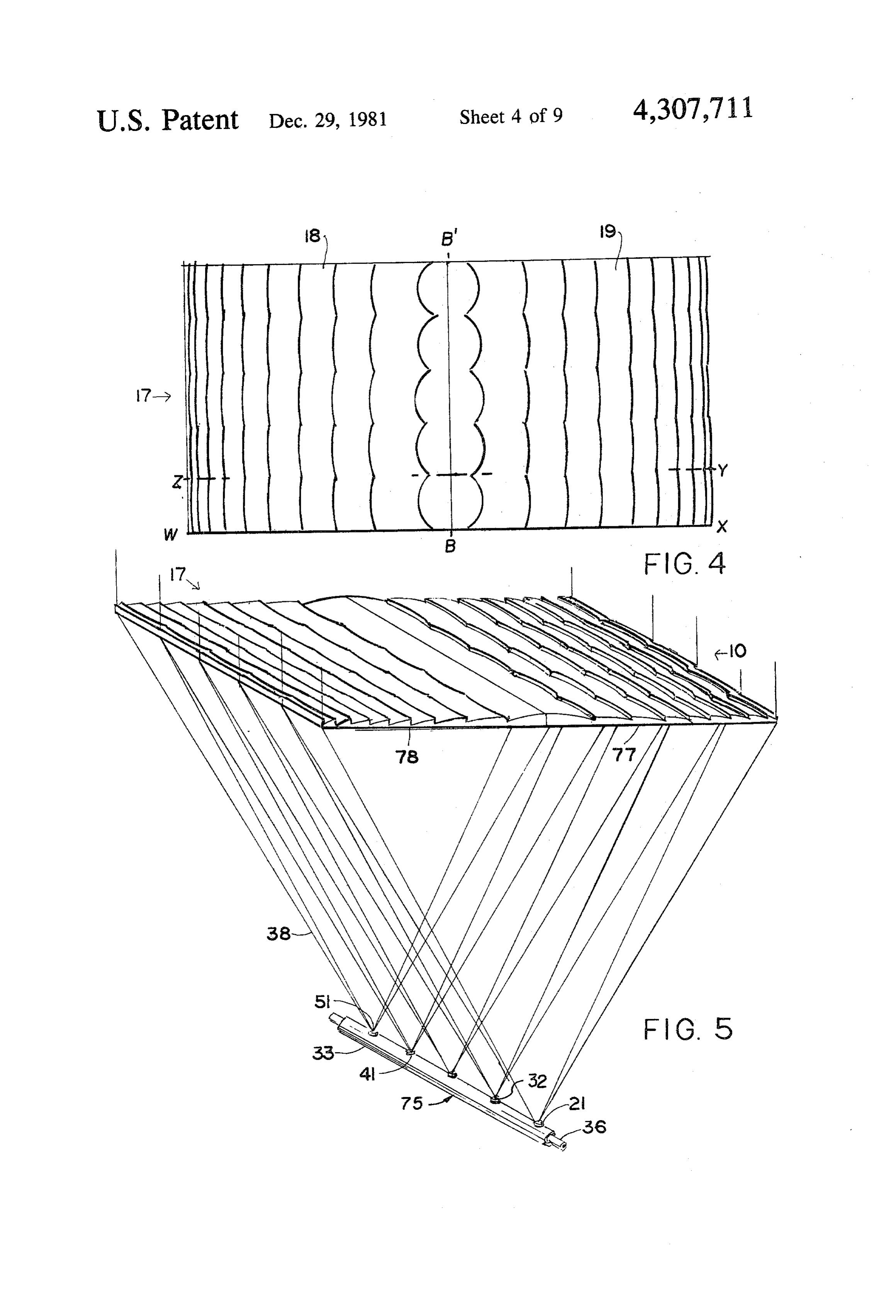
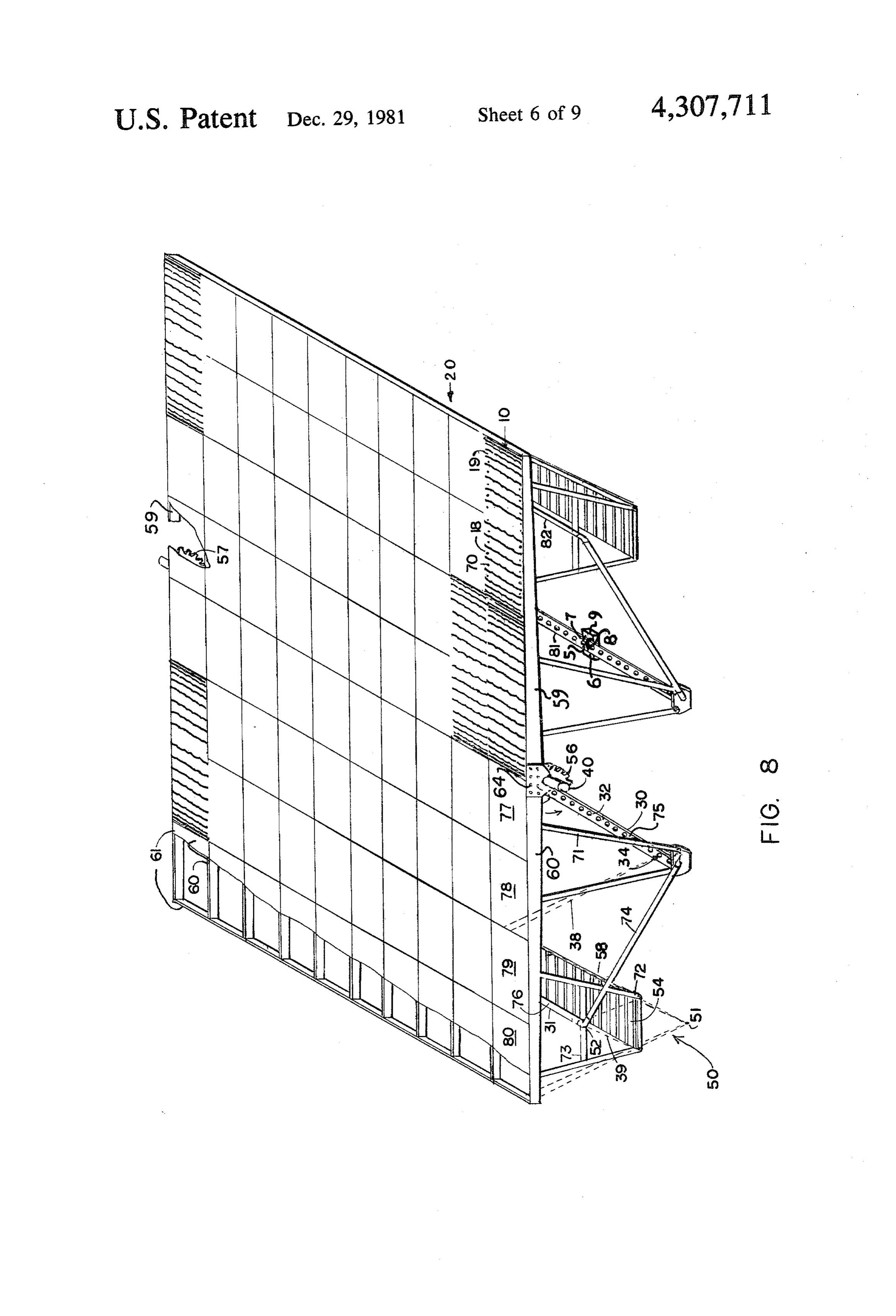
FIG. 8 shows two types of focusing. Di onto energy receiving means 75 as shown changer means. in FIG. 5 or indirect focusing through mirrors 50 onto FIGS. 3a, 3b are plan view and side view, respec energy receiving means 76, as shown in FIG. 6. tively of a refractive type focusing element means, 35 Referring now to FIGS. 2a and 2b a reflector 26 with showing the derivation of a central strip WXYZ of a focusing properties such as that of a paraboloid or a Fresnel lens, actually used in conjunction with heat spherical surface, is used as the basis for the derivation exchanger means. of an element 29 which amounts to a relatively narrow FIG. 4 is a plan view of an array of five of the central strip along the center portion of the reflector. FIG. 2b lens strips shown derived in FIGS. 3a, 3b placed side by 40 shows light rays 27 and 28 being focused towards aper side to form two symmetric lens panels. ture 32.
FIG. 5 is a side perspective view showing the lens While the reflective focusing means of FIGS. 2a and panels of FIG. 4 focusing light at 5 focal points on a 2b could concentrate the solar light onto a linear array heat exchanger, running along the focal points. of focal points 51, as shown in FIG. 8, such reflectors FIG. 6 is a side perspective view of same lens panels 45 would be harder to manufacture, to support and to keep as in FIG. 5 but with mirrors added to reflect the light properly aligned on the sun tracking platform 20. Full image back near the panels. plano-convex or double convex refractive lenses, while FIGS. 7a, 7b are side elevation cross sectional views desirable, would be extremely expensive and heavy for of the heat exchanger, its insulating cover and a glass 50 this application. The preferred type and particularly the window allowing the focused light to reach the heat basic element of the focusing means is a portion of a Fresnel lens the derivation of which is shown in FIGS.
exchanger in FIG. 7a and a solar cell in FIG. 7b.
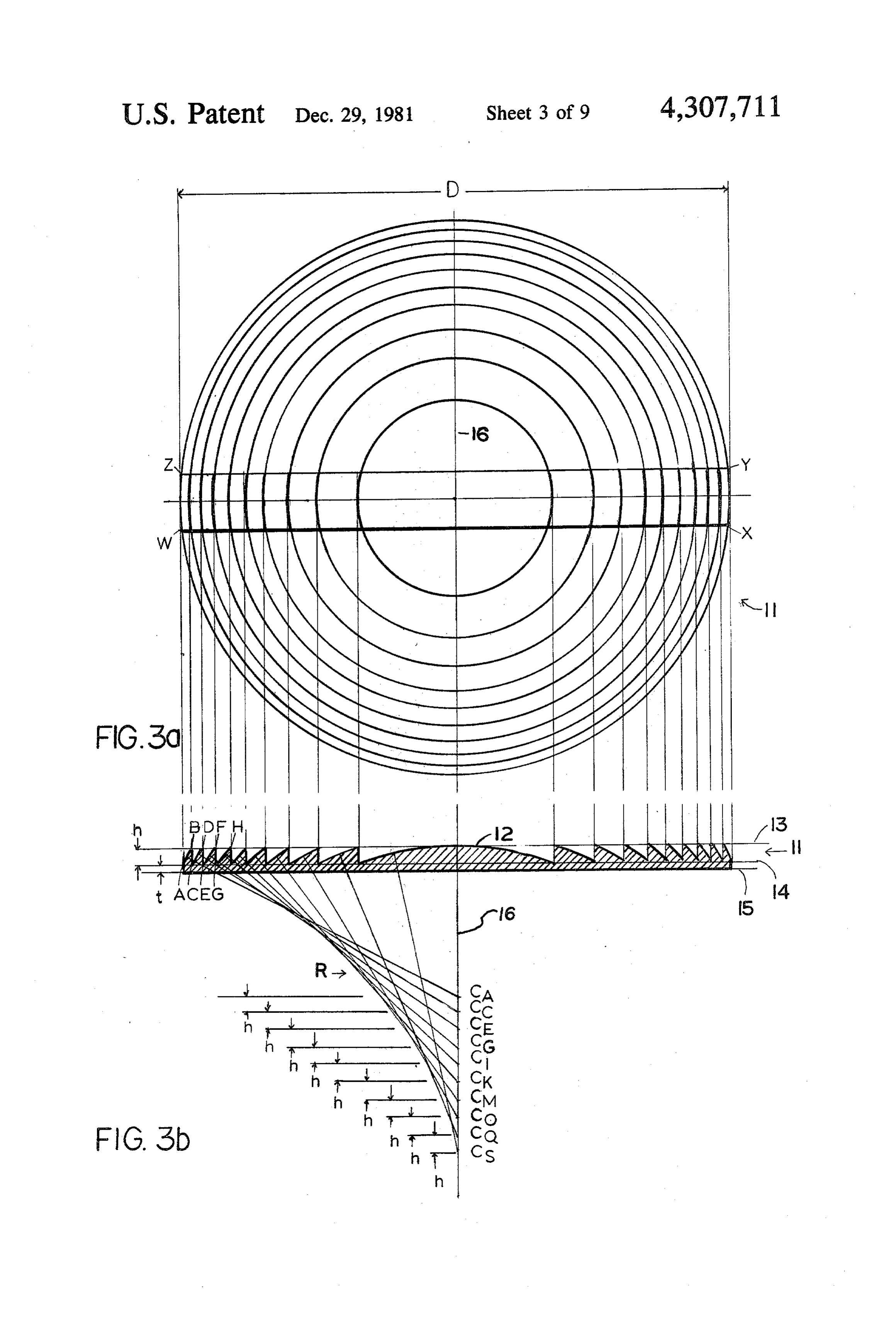
FIG. 8 is a side perspective view of a solar energy 3aTurning and 3b, now to FIGS. 3a and 3b a Fresnel lens 11 collecting platform with a plurality of lens panels in having a cross section 12 may be defined in terms of the stalled and focusing on tubular heat exchanger means 55 following parameters:
running along the foci of the lens panels through direct the diameter of the aperture of the lens D; focusing and focusing through mirrors with sections the radius R;
shown broken off for clarity. the height of the ridges h;
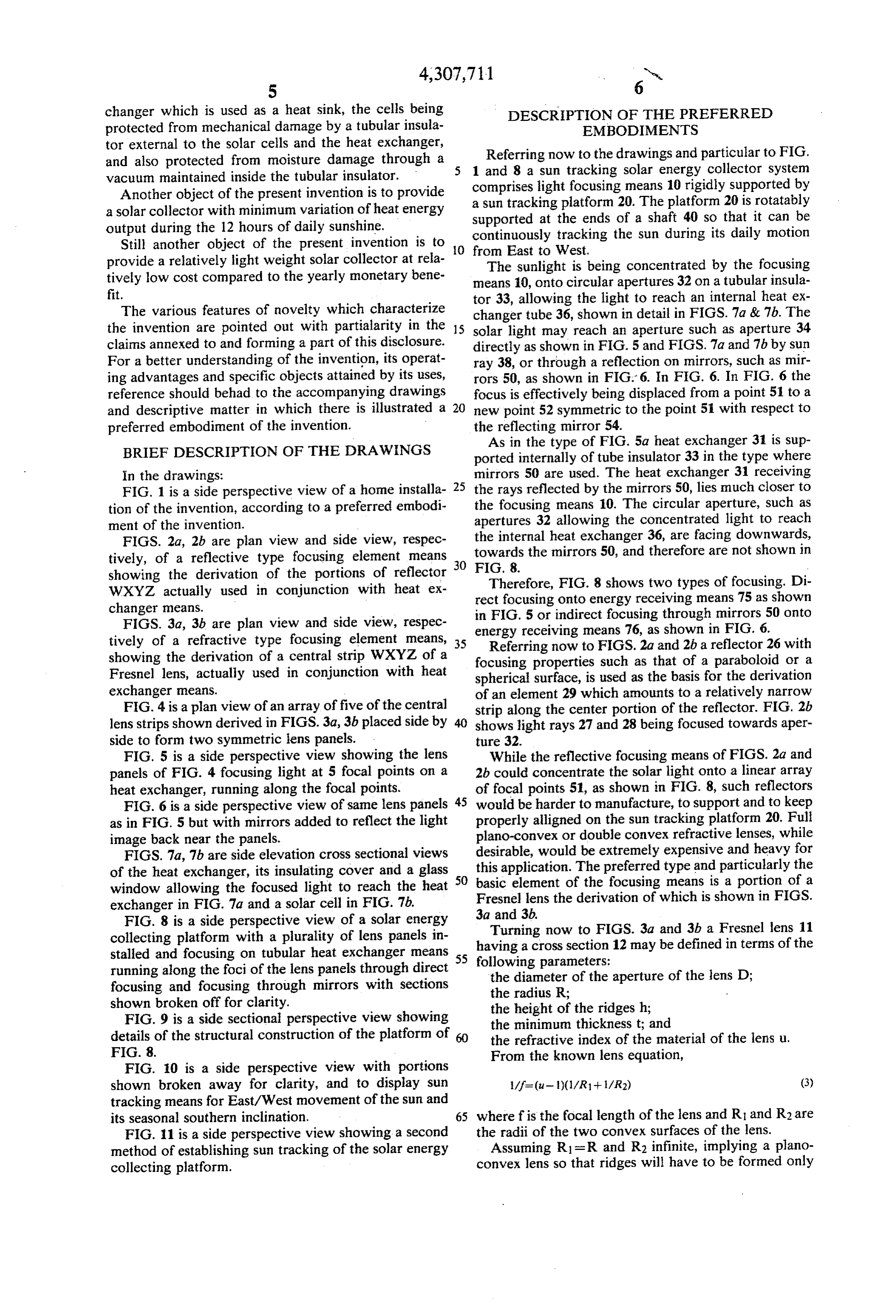
FIG. 9 is a side sectional perspective view showing the minimum thickness t; and details of the structural construction of the platform of 60 the refractive index of the material of the lens u. FIG. 8. From the known lens equation, FIG. 10 is a side perspective view with portions shown broken away for clarity, and to display sun tracking means for East/West movement of the sun and its seasonal southern inclination. 65 where f is the focal length of the lens and R1 and R2 are FIG. 11 is a side perspective view showing a second the radii of the two convex surfaces of the lens. method of establishing sun tracking of the solar energy Assuming R1 = R and R2 infinite, implying a plano collecting platform. convex lens so that ridges will have to be formed only
Page 14
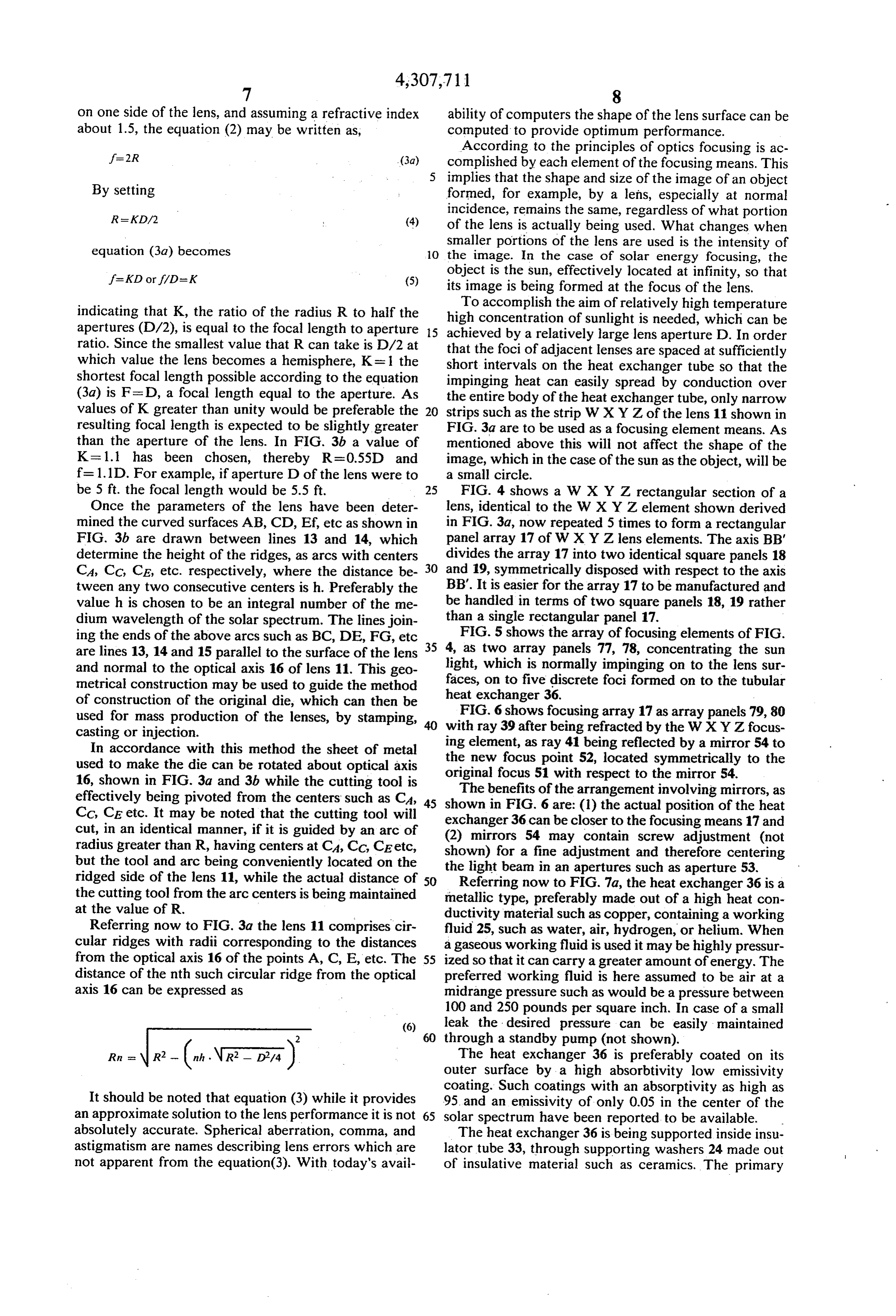
on one side of the lens, and assuming a refractive index ability of computers the shape of the lens surface can be about 1.5, the equation (2) may be written as, computed to provide optimum performance. According to the principles of optics focusing is ac complished by each element of the focusing means. This
By setting implies that the shape and size of the image of an object formed, for example, by a lens, especially at normal
incidence, remains the same, regardless of what portion of the lens is actually being used. What changes when equation (3.a) becomes smaller portions of the lens are used is the intensity of 10 the image. In the case of solar energy focusing, the
object is the sun, effectively located at infinity, so that its image is being formed at the focus of the lens.
To accomplish the aim of relatively high temperature indicating that K, the ratio of the radius R to half the high concentration of sunlight is needed, which can be apertures (D/2), is equal to the focal length to aperture 15 achieved by a relatively large lens aperture D. In order ratio. Since the smallest value that R can take is D/2 at that the foci of adjacent lenses are spaced at sufficiently which value the lens becomes a hemisphere, K= 1 the short intervals on the heat exchanger tube so that the shortest focal length possible according to the equation impinging heat can easily spread by conduction over (3.a) is F=D, a focal length equal to the aperture. As the entire body of the heat exchanger tube, only narrow values of K greater than unity would be preferable the 20 strips such as the strip WXYZ of the lens 11 shown in resulting focal length is expected to be slightly greater FIG.3a are to be used as a focusing element means. As than the aperture of the lens. In FIG. 3b a value of mentioned above this will not affect the shape of the K= 1.1 has been chosen, thereby R=0.55D and image, which in the case of the sun as the object, will be f=1.1D. For example, if aperture D of the lens were to a small circle.
be 5 ft. the focal length would be 5.5 ft. 25 FIG. 4 shows a W X Y Z rectangular section of a Once the parameters of the lens have been deter lens, identical to the WXYZ element shown derived mined the curved surfaces AB, CD, Ef, etc as shown in in FIG. 3a, now repeated 5 times to form a rectangular FIG. 3b are drawn between lines 13 and 14, which panel array 17 of WXYZ lens elements. The axis BB' determine the height of the ridges, as arcs with centers divides the array 17 into two identical square panels 18 CA, CC, CE, etc. respectively, where the distance be 30 and 19, symmetrically disposed with respect to the axis tween any two consecutive centers is h. Preferably the BB'. It is easier for the array 17 to be manufactured and value h is chosen to be an integral number of the me be handled in terms of two square panels 18, 19 rather dium wavelength of the solar spectrum. The lines join than a single rectangular panel 17.
ing the ends of the above arcs such as BC, DE, FG, etc FIG. 5 shows the array of focusing elements of FIG. are lines 13, 14 and 15 parallel to the surface of the lens 35 4, as two array panels 77, 78, concentrating the sun and normal to the optical axis 16 of lens 11. This geo light, which is normally impinging on to the lens sur metrical construction may be used to guide the method faces, heat on to five discrete foci formed on to the tubular exchanger 36.
of construction of the original die, which can then be FIG. 6 shows focusing array 17 as array panels 79, 80 used for mass production of the lenses, by stamping, casting or injection. with ray 39 after being refracted by the WXYZ focus In accordance with this method the sheet of metal ing element, as ray 41 being reflected by a mirror 54 to used to make the die can be rotated about optical axis originalthe new focus point 52, located symmetrically to the 16, shown in FIG. 3a and 3b while the cutting tool is focus 51 with respect to the mirror 54. effectively being pivoted from the centers such as CA, 45 shown The benefits of the arrangement involving mirrors, as Co, CE etc. It may be noted that the cutting tool will exchanger in FIG. 6 are: (1) the actual position of the heat cut, in an identical manner, if it is guided by an arc of (2) mirrors3654 can be closer to the focusing means 17 and may contain screw adjustment (not radius greater than R, having centers at CA, CC, CE etc, but the tool and arc being conveniently located on the shown) for a fine adjustment and therefore centering the light beam in an apertures such as aperture 53.
ridged side of the lens 11, while the actual distance of 50 Referring now to FIG.7a, the heat exchanger 36 is a the cutting tool from the arc centers is being maintained metallic type, preferably made out of a high heat con at the value of R. ductivity material such as copper, containing a working Referring now to FIG.3a the lens 11 comprises cir fluid 25, such as water, air, hydrogen, or helium. When cular ridges with radii corresponding to the distances a gaseous working fluid is used it may be highly pressur from the optical axis 16 of the points A, C, E, etc. The 55 ized so that it can carry a greater amount of energy. The distance of the nth such circular ridge from the optical preferred working fluid is here assumed to be air at a axis 16 can be expressed as midrange pressure such as would be a pressure between 100 and 250 pounds per square inch. In case of a small (6) leak the desired pressure can be easily maintained
Rn r R - (i. R dia) The heat exchanger 36 is preferably coated on its outer surface by a high absorbtivity low emissivity coating. Such coatings with an absorptivity as high as
It should be noted that equation (3) while it provides 95 and an emissivity of only 0.05 in the center of the an approximate solution to the lens performance it is not 65 solar spectrum have been reported to be available. absolutely accurate. Spherical aberration, comma, and The heat exchanger 36 is being supported inside insu astigmatism are names describing lens errors which are lator tube 33, through supporting washers 24 made out not apparent from the equation(3). With today's avail of insulative material such as ceramics. The primary
Page 15
function of the insulator tube 33 is to provide an insulat exite the junction between the two layers 45 and 46 ing space 22 between it and the heat exchanger tube 36. allowing electrons to flow from the negative connec As a vacuum the insulating space 22 will provide maxi tion 48 to the positive connection plate of heat sink 47. mum insulation. While various materials, including An external circuit connected between the connec glass, could be used to make up the insulator tube 33, tion 48, 47 can utilize the electron current flow as elec highest strength and reliability will be provided if the trical energy. A series parallel connection of a large tube 33 is made of metal. The air-tight connection at the number of cells can bring both the working voltage and ends of each straight run, needed for sealing the space current to operating levels.
between the tubes 36, 33, is preferably made of metal Only a small portion of the light absorbed by the cell which can easily be welded or brazed to each of said 10 43 is converted to electrical energy, the balance mani tubes. Since tube 33 is also made of metal it provide fests itself as heat. Further, only a small portion of this proper mechanical support and protection for the heat heat will escape through the aperture 34 back into exchanger tube 36. space. The balance will take two routes. In the first The tube 33 is provided with internal reflective sur route heat will be conducted from the cell 43 to its heat face 35, for reflecting back towards the heat exchanger 15 sink such as the heat exchanger 36 while in the second tube 36 the radiation emitted by the hot heat exchanger route heat radiated from the cell 43 arrives and is sub tube 36. The insulator tube 33, therefore, provides dual stantially absorbed by the plate or heat sink 47 and heat insulation; conductive insulation by establishing the exchanger 36 via one or more reflections from the re vacuum space 22 and radiative insulation through its flective surface 35.
reflective surface 35. 20 While normal solar cells will not withstand the high Apertures 34 spaced substantially equally along the concentrations of light referred to by the invention length of the insulator tube 33 provide passage of the recently developed cells, referred to as "concentrator focused sun ray 38 to reach the heat exchanger tube 36, cells' can process light concentrations up to 200. With at a focus region 42. normal solar cells rated up to a temperature of 257 A transparent aperture cover 21 preferably made out 25 degrees F. the concentrator cells which withstand of glass is used to provide a solid surface across the higher temperatures can be used to provide tempera apertures 34. The edge of the glass may be sealed di tures in the working fluid which will be adequate for rectly against the body of the tube 33 through special home heating and air-conditioning, hot water and even sealants. Since such sealants usually need high tempera production of additional electricity using the pressure ture treatment, it may be easier for the glass to be fabri 30 of the working fluid in the heat exchanger 36, to drive cated and sealed as a unit with a holder 41 as a separate a turbine or an engine.
process. The holder 41 with the glass can then be at While the size of the aperture 34 is desired to be small tached to the tube 33 with the combination of a screw so that only a small portion of the reflected and re thread and an anearobic sealant, for maintaining of a radiated energy will escape back to space, it may be vacuum within space 22. 35 desirable to spread the radiation through the aperture It may be noted that while a substantial amount of on to a larger surface such as the surface of the solar cell radiation is incident on a small area of the focus region 43.
42 the high conductivity of the body of the heat ex Spreading of the light beam can be easily accom changer 36 is used to quickly conduct the incident heat plished if the transparent aperture cover 21 of aperture away for the entire body of the heat exchanger thereby 40 34 is made in the form of a concave lens 44 as shown in maintaining a uniform temperature. Heat will travel FIG. 7b.
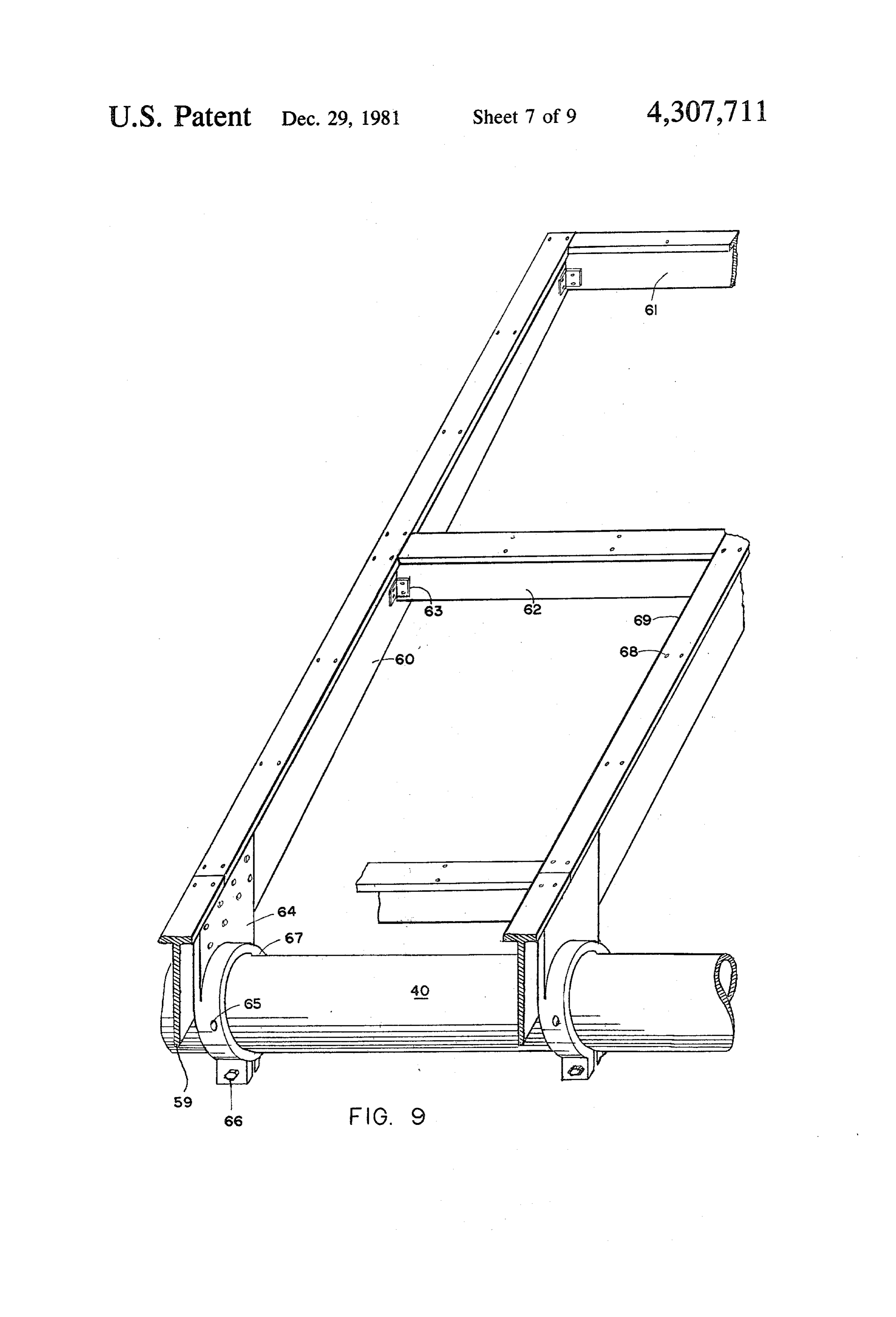
from the point of incidence of focus region 42 towards Refering again to FIG. 8 and to FIG. 9 platform 20 its opposite side along the length of the tube 36. supports a multiplicity of the light focusing means 10, in A cross section of the wall of the tube 36, other then the form of square panels such as 18 and 19. The plat a uniform wall, may exist, which will optimally distrib 45 form 20 is constructed around the shaft or spine member ute the heat in the body of the heat exchanger tube 36. 40 which is also used as a support spine for the main It is the basis of a substantially uniform temperature portion for sun tracking system. The spine member and over the body of the heat exchanger 36, that will help structure is shown in greater detail in FIG. 9. Cantilever lower radiative losses from the heat exchanger 36 members 59, 60 extend from the spine member 40 on through the aperture cover glass 21 to the outer space, 50 each side. Each pair of the cantilever members 59, 60 being that the greater portion of such radiation, falling can be fabricated from a single "I' shape extruded alu on to the reflective inner surface 35 will be returned to minum seperable in two so that each half will be tapered the heat exchanger 36. toward the end. After separation the two "T" shaped FIG. 7b shows a second embodiment of the invention beams 59, 60 are joined through a splice 64. A circum wherein the concentrated solar light illuminates a solar 55 ferential adaptor section 67 attach the pair of cantilever cell 43, whereby a significant percentage of the solar beams 59, 60 onto the spine shaft 40. Securing means energy is directly converted into electricity. Part of the such as a through bolt 65 and tightening bolt 66 may be light will be reflected by the surface of the solar cell and used for securing the adaptor section 67 to the spine part of the reflected light will escape back towards shaft 40.
space through the aperture 34. A substantial amount of 60 Aluminum spot welding may also provide further such radiation will remain inside the tube 33 by being strength to the connection between the adaptor section re-reflected from the surface 35, of the tube 33, to the 67 and the spine 40. The splice member 64 and the solar cell 43. adaptor section 67 may be preferably cast as one piece Solar cells are usually photovoltaic cells comprising a out of a suitable metal. Webs 69 formed by the top of the photosensitive surface 45, made out of N-type silicon, a 65 "T" beams provide rigidity of the cantilever members P-type layer 46 which also provides the positive con 59, 60 along the plane of the platform 20. In addition nection plate 47 and a negative connection 48. When webs 69 provide a convenient means for securing the the cell 43 is illuminated the light quanta penetrate to panels 18, 19 on to the platform 20 by screws 70 shown
Page 16
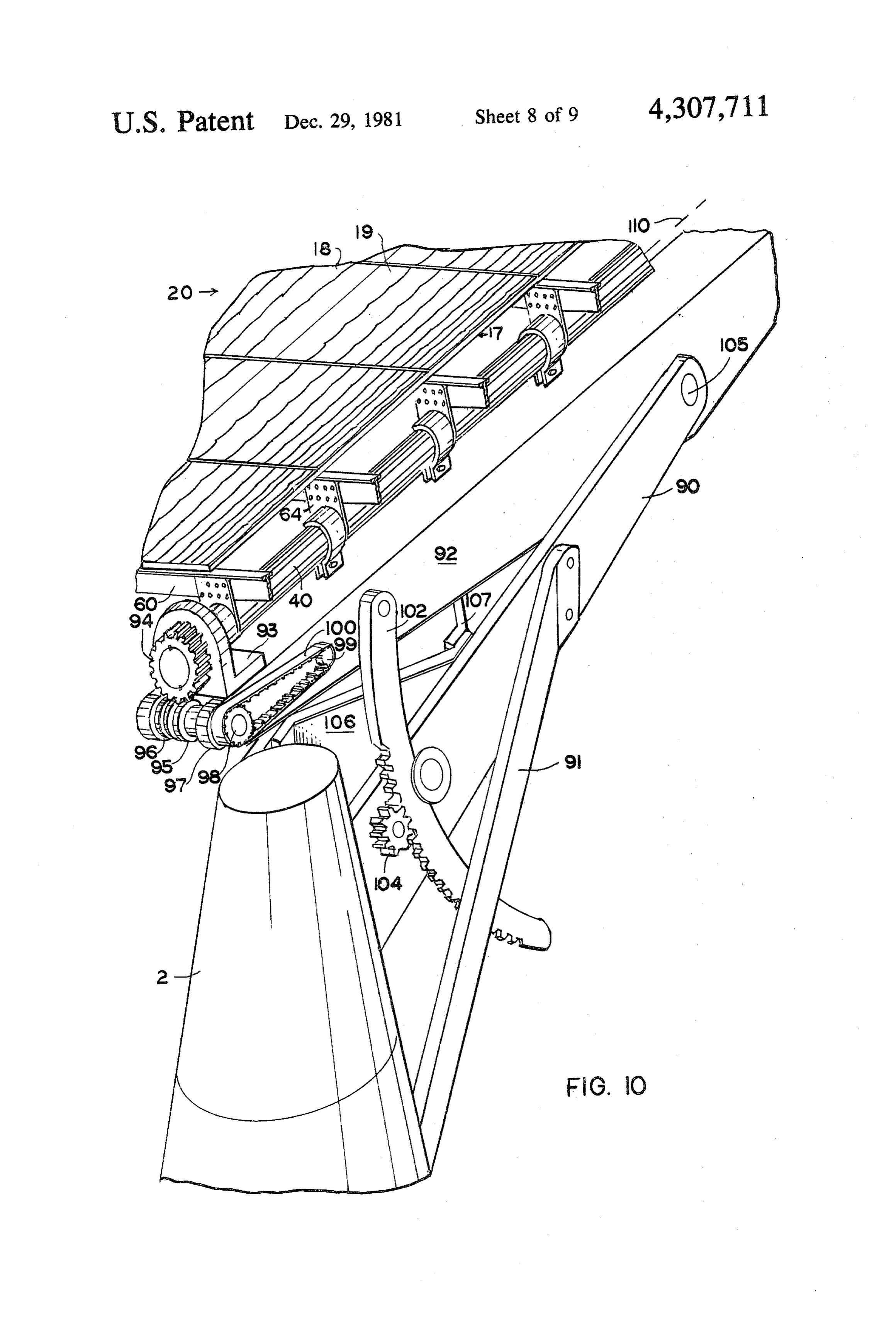
in FIG. 8 through holes 68 provide on the web 69 as second spracket 98 coaxially and rigidly attached to shown in FIG. 9. Accurate positioning and further same shaft as the worm gear 95. rigidity of the cantilever members 59, 60 in the plane of Sun tracking due to the southern seasonal declination the platform 20, is provided by brace members 62 inter of the sun is accomplished by drive motor, not shown, posed between and secure with the cantilever members driving through a gear train, a gear 104 which adjusts by means of brackets 63.
While one type of focusing, either direct focusing athetoothed angle of the “U” beam 92 about pivot 105, through arced member 102.
such as shown in FIG. 5 or focusing through mirrors 50 such as shown in FIG. 6, may be used throughout the voltage whentracking
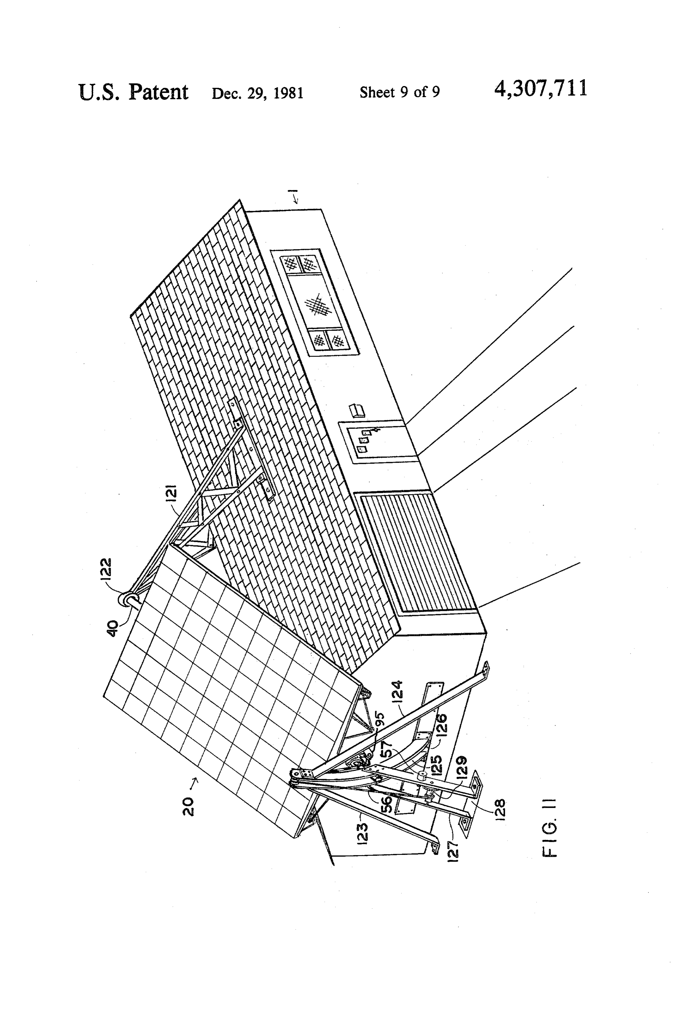
Automatic the is achieved by the rise of an error normal to the platform is displaced platform, FIG. 8 shows both types of focusing used 10 from the line to the sun. Two pairs of photosensitive with the same platform. Thus, the array panels 77 and 78 are directly focusing light into an array of foci elements such as phototransistors are employed to de formed along the heat energy receiving means 75. The tect North/South and East/West deviations. Thus pho heat energy receiving means 75 is supported by the totransistors 5 and 8 positioned next to an aperture cantilever members 60 of the platform 20, through sup 15 northward and southward, respectively, can provide a porting members 71. North/South error in terms of a voltage developed as a Panels 79 and 80 gather focused light by combining difference of currents provided by the phototransistors. their focusing through mirrors 50 at the new focal point When the platform it tilted too much to the South the 52. The energy receiving means 76 comprises heat ex transistor 8 will provide more current than transistor 5 changer 31 and heat exchanger tube 36 inside the insula 20 causing the motor driving the gear 104 to rotate in the tor 33. Apertures such as apertures 53 of insulator 33 are direction that will tilt the platform 20 Northwardly thus facing towards the mirrors 59 and therefore cannot be eliminating the error. A second pair comprising photo seen in FIG. 8. The mirrors 50 previously described in transistors 6 and 7 operate in a similar way for East/W- FIG. 6 are supported by support members 72 in con est positioning of the platform. Box 9 in the vicinity of junction with a mirror supporting platform 58. 25 the phototransistors 5, 6, 7, 8 serves to house the proper A connecting section 74 connect the energy receiv power supply and the electronic circuitry which is ing means 75, 76 to permit heat interaction therebe commercially available. An omnidirectional light detec tween. The section 74 comprises an inner tube such as tor, not shown, can provide signal to the electronic 36 and an insulator tube such as 33 but no apertures. circuitry in box 9 when the sun rises in the morning or Energy receiving means 76, 75, and 81, 82 shown in 30 the sun reappears during a cloudy day. Such signal can FIG.8 may be connected in series or in parallel depend provide sweep signals to the control circuitry so that ing on sizes and temperatures involved in a particular the direction of the platform towards the sun can be system. re-initiated.
Various methods may be employed for having the Referring now to FIG. 11, a second method is shown platform 20 supported and tracking the sun. While it 35 for supporting and guiding the platform 20, to track the may be easier to have the platform 20 supported and sun. A truss 121, supported on to the roof of the house positioned, so that its surface remains substantially nor 1, provides a swivel ball joint for rotatably supporting mal to the rays of the sun, be means attached to the roof the shaft 40 at the upper side. At the lower side the shaft of the building, it will be preferable if the platform 20 is 40 supported by a tower based on solid ground. Such inde 40 125isand permitted to be displaced between two members 126 forming an arc about a center located at the pendent means of supporting and positioning the plat swivel ball form 20 will preclude the danger of damage to the the shaft 40joint 122. The members 125 and 126 restrict from side movement but permit it to rotate house structure by the platform. about its axis. They also provide an effective slot in FIG. 1 shows such a preferred arrangement where a which the shaft 40 can be displaced vertically along the platform 20 is supported over the southern part of the 45 arc. This can be accomplished in terms of a cable 56 house roof of a house 1. The platform 20 carrying opti cal panels 18, 19, is being supported by a tower 2, hav which is wound or unwound around a winch 129 by the action of a drive motor 57. Structural members 27, 23 ing a foundation 3.
A greater detail about the preferred method of sup and 124 provide support for the weight thrust which the platform exerts mainly towards the ground support port and positioning of the platform 20 is shown in FIG. 50 members. East/West rotation of the platform is accom
Referring now to FIG. 10, the tower 2 provides an plished substantially similarly as previously described in inclined truss 90, which provides a pivot 105 about terms of a worm drive 95 and worn gear 94 shown in which the platform 20 can be tilted to point toward the FIG. 10. Guidance signals are provided as previously sun as its seasonal southern declination varies. The truss 55 described in terms of the phototransistors 5, 6, 7, 8, and 90 is internally reinforced by cross members 106, 107. the electronic circuitry in box 9.
The truss 90 is structurally re-inforced by a support While specific embodiments of the invention have member 91, rigidly connected to the tower 2. The spine been shown and described in detail to illustrate the shaft 40 is rotatably supported by a yoke formed by a application of the principles of the invention, it will be "U" beam 92 and two angle brackets 93. A gear 94 is 60 understood that the invention may be embodied other rigidly attached to the shaft 40 so that, in conjunction wise without departing from such principles. with a worn gear 95, the shaft 40 and therefore the What is claimed is:
entire platform 20 can be rotated to track the sun during 1. A solar energy collector comprising: its daily movement. The worm gear 95 is rotatably a hollow insulator member having an interior well supported by extenions 96, 97 of the U beam 92. Rota 65 defining a free space and having a plurality of aper tion of the worm gear 95 is provided by a drive motor, tures therethrough of a total surface area substan (not shown), providing rotation to a drive spiracket 99, tially less than that of a remainder of the insulator which is connected through a chain or belt 100 to a member; -
Page 17
a heat conductive member disposed in the free space, second cylindrical tube having a heat-absorbent spaced inwardly of said interior wall and adapted surface.
to receive a heat transferring medium; and 2. A solar energy collector according to claim 1 fur solar energy focusing means associated with said ther including a light transparent window disposed insulator member for focusing solar energy into the 5 across each of said apertures.
space through said apertures and onto said heat 3. A solar energy collector according to claim 2 conductive member at impinging point to heat said wherein a partial vacuum is established in the space. heat conductive member whereby a heating of said 4. A solar energy collector according to claim 1 heat conductive member is conducted away from wherein said solar energy focusing means comprise an the impinging points and to the heat transferring 10 array of substantially rectangular focusing lensing. medium; 5. A solar energy collector according to claim 1 said heat conductive member being made of material wherein said solar energy focusing means includes a which conducts heat easily; and said insulator member interior well having a radiation solar energy onto the impinging panel substantially rectangular focusing for focusing the points, said focusing reflecting surface whereby most of the energy radi 5 ated from said heat conductive member after it is panel connected to said insulator member and spaced heated is reflected back toward said heat conduc therefrom, said means for scanning the sun connected to tive member wherein said hollow insulating mem said focusing panel and connected insulator member for ber comprises a first cylindrical tube having said moving said focusing panel and connected insulator plurality of apertures disposed along a line extend- 20 member.
ing parallel to a major axis of said first cylindrical 6. A solar energy collector according to claim 1 tube, said heat conductive member comprising a wherein said solar energy focusing means comprise a second cylindrical tube having a diameter less than plurality of substantially rectangular Fresnel lenses. that of said first cylindrical tube and being metallic 7. A solar energy collector according to claim 1 with an annular space defined between an outer 25 wherein said solar energy focusing means comprises a wall of said second cylindrical tube and an inner planar panel of light refracting elements extending in a wall of said first cylindrical tube, each of said aper plane which is parallel to and spaced from a tangent tures covered, in a gas-tight manner with a window plane to an exterior surface of said first cylindrical tube plate, said annular space having a partial vacuum containing said plurality of apertures. established therein and said exterior wall of said 30 sk sk. k. sk
Provenance
- Collection
- Cited prior art
- Original PDF
- patentimages.storage.googleapis.com →
- Filed
- 1980-02-25
- Pages
- 17
- Method
- pdftotext (the PDF's own text layer) + pdftoppm 300dpi page scans
- Source
- Google Patents bibliographic record
- Granted
- 1981-12-29
- Inventors
- George J. Doundoulakis
- Transcribed from
- patentimages.storage.googleapis.com →