patent · US6227280
Sunshade of the type of a venetian blind
8 May 2001
Page 1 — bibliographic record
(12) United States Patent (10) Patent No.: US 6,227,280 B1 Wirth et al. (45) Date of Patent: May 8, 2001
(54) SUNSHADE OF THE TYPE OF A VENETIAN 2,572,957 : 10/1951 Shaw ................................ 160/236 X BLIND 4,398,587 8/1983 Boyd.
4,486.073 * 12/1984 Boyd ................................ 160/236 X (75) Inventors: Harry Wirth; Andreas Gombert; 4,509,825 4/1985 Otto et al. ........................ 160/236 X Volker Willwer; Jörg Jungjohann, all 4,773,733 9/1988 Murphy, Jr. et al.. of Freiburg (DE)
FOREIGN PATENT DOCUMENTS
(73) Assignee: Fraunhofer-Gesellschaft Zur
Forderung der angewandten 44 42 870 A1 3/1996 (DE).
Forschung e.V., Munich (DE) * cited by examiner (*) Notice: Subject to any disclaimer, the term of this patent is extended or adjusted under 35
U.S.C. 154(b) by 0 days. Primary Examiner-David M. Purol (21) Appl. No.: 09/319,442 (74) Attorney, Agent, or Firm-Staas & Halsey LLP
(86) PCT No.: PCT/DE97/03017 A Venetian type Sunshade comprising a plurality of parallel lamellae with horizontally extending respective longitudinal
S371 Date: Aug. 9, 1999 axes, which are adapted to be rotated about their respective S 102(e) Date: Aug. 9, 1999 longitudinal axes using an adjusting mechanism. The lamellae, or a layer applied on the upper Side of the lamellae, (87) PCT Pub. No.: WO98/29633 consists of a material transparent to Sunlight. Each lamella PCT Pub. Date:Jul. 9, 1998 has an upper Side, a plurality of ribs, and a third face. Each rib has a first face arranged obliquely relative to the upper (30) Foreign Application Priority Data side of the lamella and adapted to be irradiated by the Sun in Jan. 3, 1997 (DE) ............................................... 197 OO 111 an approximately vertical direction, and a Second face which is arranged flush and at an acute angle of roughly 45 (51) Int. Cl. ............................................. E06B 9/26 relative to the first flat element. The third face is approxi (52) U.S. Cl. .................. ... 160/166.1 R; 160/236 mately orthogonal to the Second faces. Adjacent ribs define (58) Field of Search ................................ 160/236, 173 R, a mutual spacing which permits a low shade irradiation and 160/168.1 R, 176.1 R, 166.1 R; 359/596, emission through the first faces when there is approximately 592 perpendicular irradiation of the first flat elements, with the optical connection between the mutual spacing being within (56) References Cited the thickness between the upper Side of a lamella and the third face.
2,103,788 12/1937 Mohrfeld. 19 Claims, 3 Drawing Sheets
Page 2
Drawing sheet — no readable text.
Page 3
Drawing sheet — no readable text.
Page 4
Drawing sheet — no readable text.
Page 5
SUNSHADE OF THE TYPE OF A VENETIAN the lamellar elements, as related to the Solar elevation angle BLIND that varies during the course of a day.
FIELD OF THE INVENTION Within FIG. 2, “Ref. View” plots the portion of the area which remains between the prismatic lamellae according to
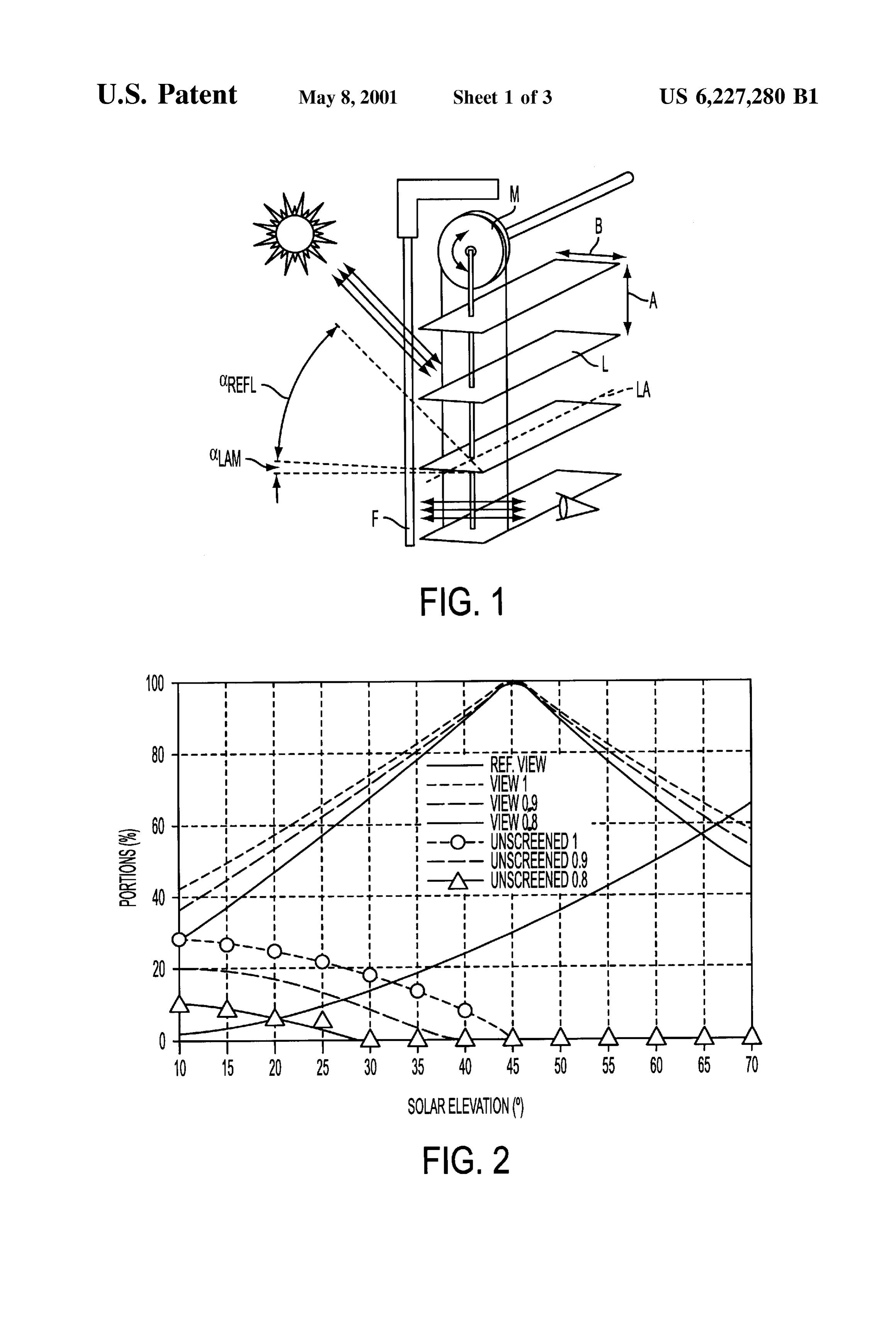
The present invention relates to a Venetian blind type the above-described European publication and which can be Sunshade having a plurality of lamellae which are arranged Seen through in the horizontal direction, in dependence on in parallel with each lamella having Substantially plane face the position of the Sun. It can be seen that, with the Sun in elements along a respective longitudinal axis wherein each a high position, the Single lamellar elements must be ori lamella may reflect received Sunlight while maintaining a ented at a Smaller angle, whereby the unrestricted through through-view along the horizontal direction. View between two adjacent lamellar elements becomes larger than in the case of Sun positions having only low
PRIOR ART elevation. “Ref. View,” as shown, is based on an aspect ratio Known Sunshades, Such as lamellar Venetian blinds made A/B of 1.
of vinyl or aluminum, do not both afford protection from the 15 Because of the requirement of an orientation of the direct glare of Sunlight inside rooms and allow Selective individual lamellae perpendicular to the incident Solar rayS, transmission of light for the entry of daylight So that artificial the through-View characteristics become Substantially light inside a room may be dispensed with. Moreover, impaired. In order to avoid the disadvantages of an orien lamellar Venetian blinds, particularly in a condition of tation Substantially perpendicular to the Sun, lamellar struc completely Screening-off, do not allow any possibility of an tures have been conceived from which the light which is optical through-view to the outside, which would be desir incident obliquely on the lamella Surface is also reflected able to improve the quality of the living and working obliquely. Such arrangements are evident from the docu environment in the rooms thus Screened-off. ments DE 44 42 870 A1 and DE 4444.509 A1. The lamellae Generic Screening Systems are known which disperse described there for precisely controlling the direct Solar Sunlight with optically non-transparent materials used for 25 irradiation have a Sun-facing Saw-tooth-like Structure which, lamellar Venetian blinds and utilize the fact that, with direct however, is coated with a metal coating. However, the Solar irradiation on Surfaces of buildings or windows, up to disadvantage of these known Sunshade Systems is the Strong 80% of the irradiating light intensity originates from a Solar heating of the metal Surfaces, because they absorb between or circumSolar Spatial angle. These Sunshade Systems, which 5 and 15% of the incident energy, depending on the actual are mainly made of optically transparent materials, have design. Moreover, the individual lamellar elements are opti directionally Selective transmissive properties and Screen-off cally non-transparent because of the metal coating. the light coming from undesired angles, preferably that from Sunshades of large area having a lamella-like Structured the Solar spatial angle. However, these Systems are Substan Surface are known, for example, from the publications GB 2 tially optically transparent for light components from other 220 025 A and GB 217O 256 A. Both cases involve facade directions. Examples of Such Sunshade Systems are known, 35 coverings transparent to Sunlight, which are preferably Suit for example, from U.S. Pat. No. 631,220, U.S. Pat. No. able for greenhouses, and deflect the Sunlight at a desired 3.255,665 and U.S. Pat. No. 737,979. angle of incidence into the interior of a greenhouse. Because the angle of Solar elevation changes Steadily in Although total reflections occur with a Suitable optical the course of a year, it is necessary either for Such direc arrangement of the optically active Surfaces of the tionally Selective Sunshade Systems to be adapted to the 40 Sunshades, in the case of FIGS. 2 and 3 of GB 2170 256, actual position of the Sun (so-called “active elements”), or the light is not reflected back in the same direction from for the directionally Selective properties to be So designed which the light is incident on the Sunshade. Glare effects in that they permanently Screen-off a very wide range of Spatial the environment are unavoidable.
angles of the sky (so-called “passive elements”). BRIEF DESCRIPTION OF THE INVENTION One example of active elements is described in the EPO 45 090830, which shows a Sunshade designed in the form of An object of the invention is to provide a Venetian blind lamellae using a material transparent to light. The plurality system that substantially allows through-view while Sub of lamellae are parallel to each other, and are each rotatable Stantially reducing glare.
about their respective longitudinal lamella axes have a plane A further object of the invention is further developing a Surface facing the Sun, the opposite Surface having a pris 50 Venetian blind type Sunshade having a plurality of lamellae matic structure preferably consisting of prismatic rods which have Substantially plane face elements of elongated aligned in parallel. For effective protection from the Sun, the configuration, wherein each lamella may be irradiated by the individual Surfaces facing the Sun must be aligned approxi Sun at Such an angle that a through-view along the horizontal mately perpendicularly to the prevailing incident light So direction is Substantially retained, the development being that the light rays incident on the individual lamellae of an 55 that the characteristics of the view through the Sunshade are optically transparent material are reflected back to the out Substantially unimpaired or only slightly impaired while any Side by total reflection. Although the known Sunshade per dazzling or glare effects caused by the Sunlight directly mits the entry of daylight into the interior of a room, it incident into the interior of a room are prevented. In blocks the through-view considerably because of the nec particular, the Sunshade should not display any Self-heating essary orientation perpendicular to the Sun. 60 and should be made of an optically transparent material. The aspect ratio A/B, which indicates the ratio of the According to the invention, a Venetian blind type Sun inter-lamellar spacing A between two adjacent lamellae of shade having a plurality of lamellae that are arranged in the Venetian blind to the lamella width B, serves as a parallel with horizontally extending longitudinal axes and geometric index for lamellar Venetian blinds. FIG. 2 shows which are rotatable about respective longitudinal axes by a diagram representing, as a percentage, the portion of the 65 means of an adjusting mechanism is designed in Such area between the lamellar elements which is available for an manner that each lamella, or a layer coated on the upper side unrestricted through-view in depending upon the Settings of of the lamella, consists of a material transparent to Sunlight
Page 6
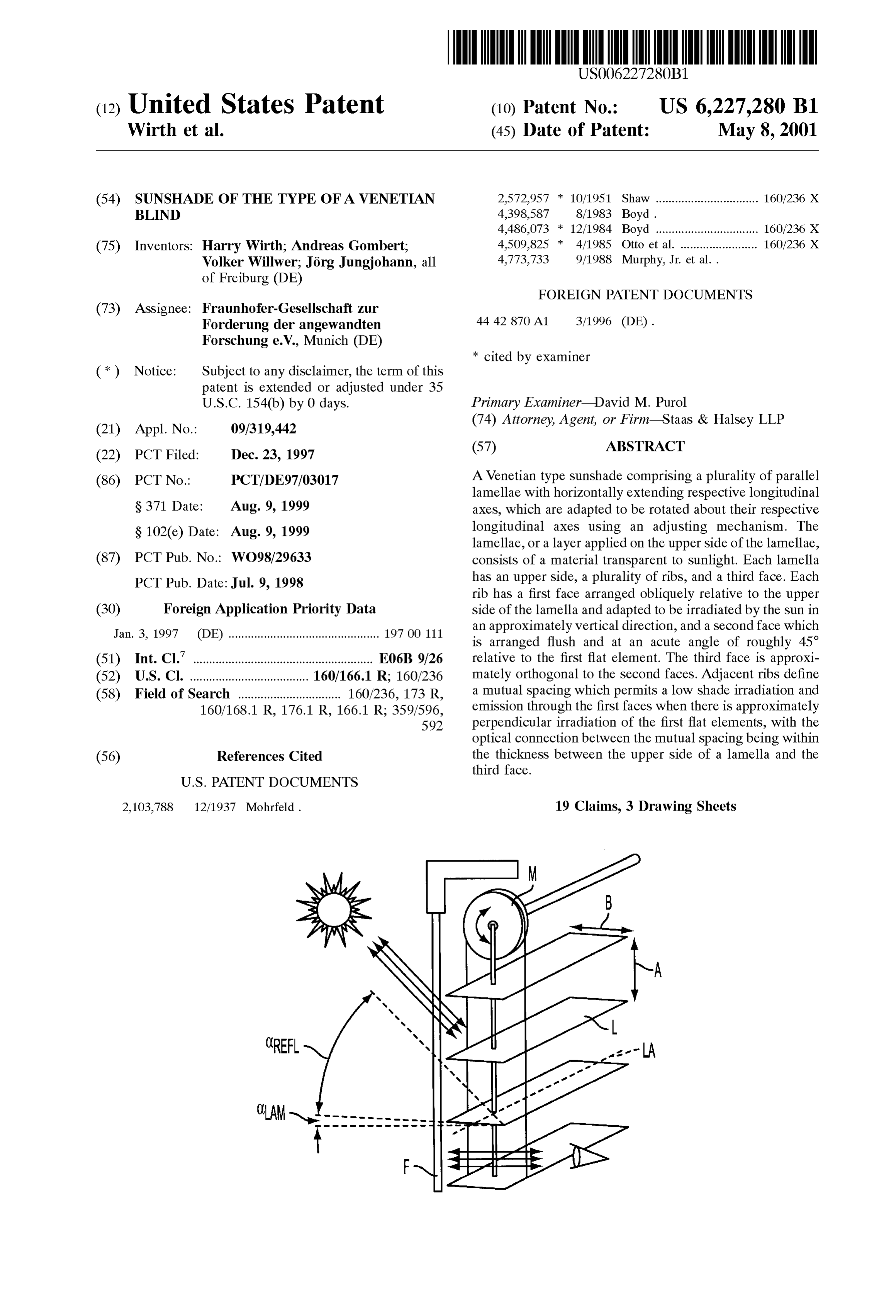
and has a croSS-Section, which is composed of the following are illustrated in the accompanying drawings, wherein like face elements: (a) first face elements which are disposed reference numerals refer to the like elements throughout. obliquely to the upper Side of the lamellae and can receives The embodiments are described below in order to explain Sunlight approximately perpendicularly; (b) second face the present invention by referring to the figures. elements which are disposed flush with and at an acute angle The Sunshade illustrated in FIG. 1 has lamellae L, the of about 45 to the first face elements; and (c) a third face horizontal orientations of which can be adjusted via a drive element which is disposed to be approximately perpendicu mechanism M, each having a width B and a mutual spacing lar to the Second face elements. A. In the example shown, the lamella arrangement is In particular, adjacent pairs of first and Second face mounted behind a window F in order to prevent light rays elements have a mutual spacing which, when Said first face which directly come from the Sun from entering the interior elements are irradiated approximately perpendicularly by of the room. In order to improve the through-view charac Sunlight, permits irradiation by and emission of the Sunlight teristics of the Sunshade, i.e. to maximize the portion of the via the first elements with little screening. Moreover, the areas enabling a through-view between the lamellae L, the only optical connections permitted acroSS this spacing are Surfaces of the lamellae are of Such nature that Solar rays within the thickness between the upper surface and the third 15 incident on the Surfaces preferably at an angle of 40 to 55 face. with respect to the Surface plane are reflected back within an The orientation of the Surfaces of the optical connecting angular range Crg. The planes of the lamellae can be moved elements parallel to the third face elements ensures that around their respective longitudinal axes LA through an direct Sunlight can leave the lamella exclusively via the first angle C. The Sunlight incident on the lamella Surfaces is face elements. This aspect is important in order that errors of reflected back preferably in the same direction as that from adjustment and other deviations from the ideal ray path do which it is incident on the Surface.
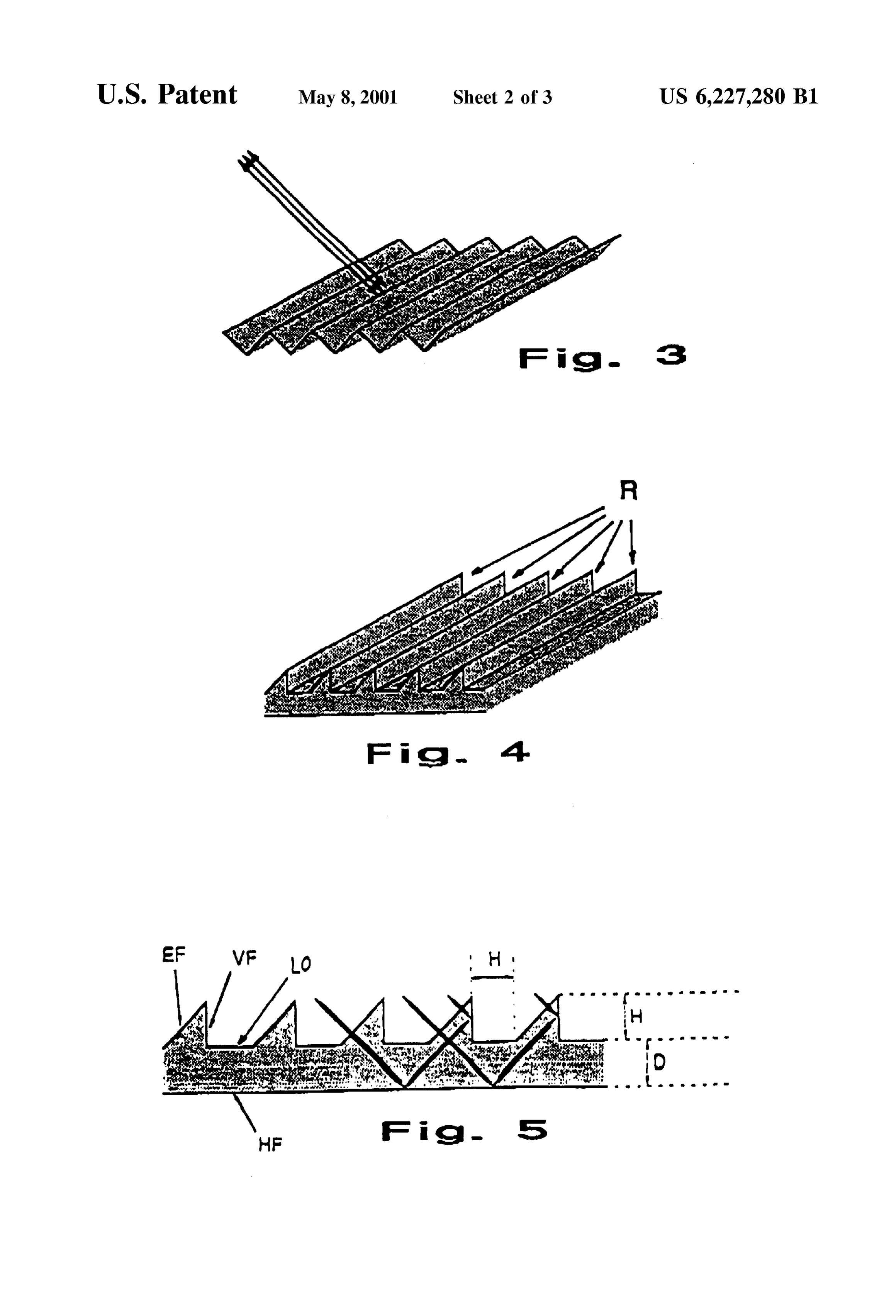
not impair the functioning of the lamella. Preferably the front lamella edges facing the Solar irra The invention is based on the concept of the Sunlight diation are provided with a reflecting coating on their being incident on the upper Side of the lamella, preferably at 25 underSides, So that back reflected light rays which are an angle of about 40 to 45, and being reflected back from reflected at a Steeper angle of reflection and are thus incident there by total reflection, preferably in the same direction as on the underside of the next higher lamella may be deflected that from which the Sunlight is incident on the Sunshade. In to the outside by the reflecting layer. this way, an effective Sun Shading can be achieved at A furrowed or Saw-tooth Surface having face portions relatively small inclinations of the individual lamellae about oriented Substantially perpendicularly to the incident light their longitudinal axes. This results in the portions of the rays basically Serves as a Suitable Surface Structure which is area available for an unrestricted horizontal through-view either additionally applied onto the Surface of each lamella between the individual lamellae being very large in com as a structured layer of transparent material, for example a parison with conventional Venetian blinds which require a transparent film, or constituted by the lamella itself. FIG. 3 normal, i.e. perpendicular, orientation of the lamellae to the 35 shows, as an example of a Suitably reflecting Surface SU. Structure, a Substantially furrowed Surface having face por Additional objects and advantages of the invention will be tions which are oriented perpendicularly to the incidence of Set forth in part in the description which follows and, in part, light and at which the incident light is reflected back in the will be obvious from the description, or may be learned by Same direction as that from which it is incident on the practice of the invention. 40
Surface.
BRIEF DESCRIPTION OF THE DRAWINGS FIG. 4 illustrates an embodiment of a lamella layer, or only an upper part of a complete lamella, according to an
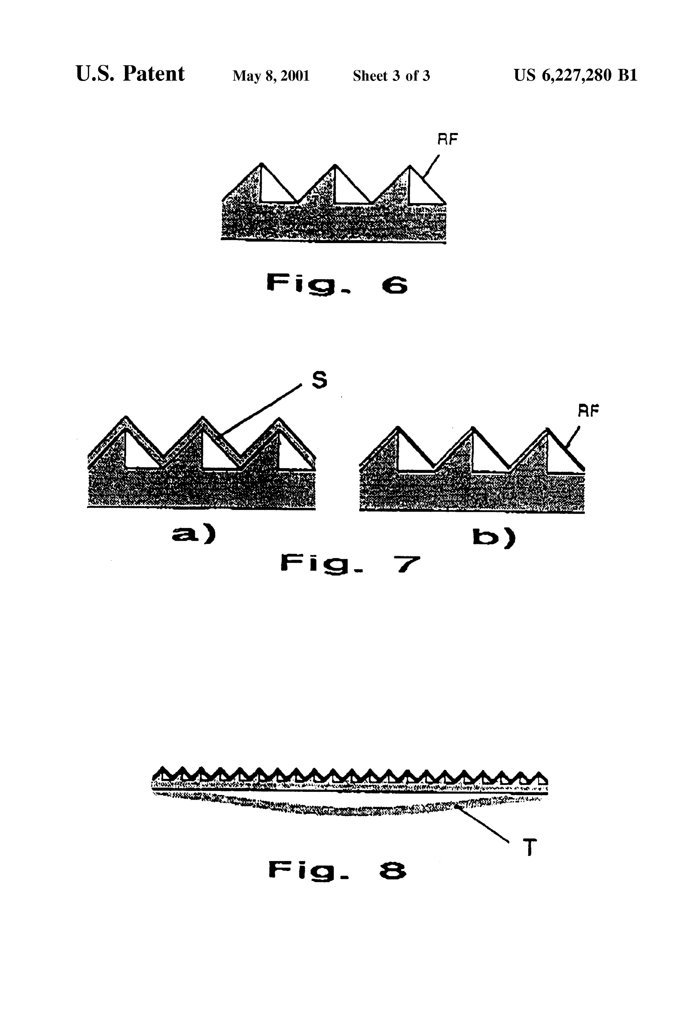
These and other objects and advantages of the invention embodiment. The Surface facing the Sun has a Succession of will become apparent and more readily appreciated from the ribs R extending in parallel and having cross-sections cor following description of the preferred embodiments, taken 45 responding to a saw-tooth Structure. The underside of the in conjunction with the accompanying drawings of which: lamella, by contrast, is formed to be plane. FIG. 1 is a Venetian blind arrangement with an adjusting FIG. 5 illustrates a cross-section of the lamella Surface mechanism. Structure according to an embodiment. The first face EF, also FIG. 2 is a diagrammatic illustration with variable aspect referred to in the following as a receiving face, is inclined to ratioS. 50 the upper Side LO of the lamella, and can be Substantially FIG. 3 is a perspective illustration of a saw-tooth struc oriented to be normal to the Sun by the lamella as a whole ture. being oriented according to the Sun. The Solar rays penetrat FIG. 4 is a perspective illustration of a lamella surface ing the receiving face EF Substantially perpendicularly are Structure according to the invention. incident on a third face HF extending parallel to the lamella FIG. 5 is a cross-sectional view through a saw-tooth 55 plane, from which they are totally reflected. The totally Structure according to the invention. reflected ray components Subsequently arrive at a Second FIG. 6 is the example of embodiment according to FIG. face VF, oriented to be substantially perpendicular to the 5 with a reflecting layer. upper side LO of the lamella, from which they are totally FIGS. 7a, b are examples of embodiments according to reflected a Second time, whereby the light rays deflected in FIG. 5 with additional reflecting layers. 60 this manner Substantially travel in a direction opposite to FIG. 8 is a Venetian blind lamella with an additional that from which they were incident on the receiving face EF. reflecting layer. The light rays deflected or back-reflected by the lamellar structure illustrated in FIG. 5 emerge into free space Sub
DESCRIPTION OF THE PREFERRED Stantially via the receiving face EF.
EMBODIMENTS 65 Because of the planar arrangement of the lamellae, it is Reference will now made in detail to the present preferred necessary, geometrically, to dispose a plurality of Successive embodiments of the present invention, examples of which parallel ribs having a Substantially saw-tooth Structure
Page 7
S 6 across the width B of the lamella L. However, due to the the recommended minimum thickness of the additional layer structural height H of the individual structural elements and S should be 0.16.H.
their mutual spacing, which preferably should be of the same AS an alternative to the Solid design of the layer according order of magnitude H, problems will arise because Succes to the embodiment of FIG. 7a, the embodiment according to Sive elements mutually Screen-off each other. The cause of FIG. 7b provides a thin coated layer on the structural the Screening is both the finite Spatial angle of the Sun and elements, wherein the layer thickness dA may be chosen to the practically unavoidable error in directing the lamellae be arbitrarily Small. Only the connections between Succes with respect to the Sun. Thus, either the receiving faces EF Sive perpendicular layers and receiving layerS should be of adjacent Structural elements will partially Screen-off each coated with a reflecting layer.
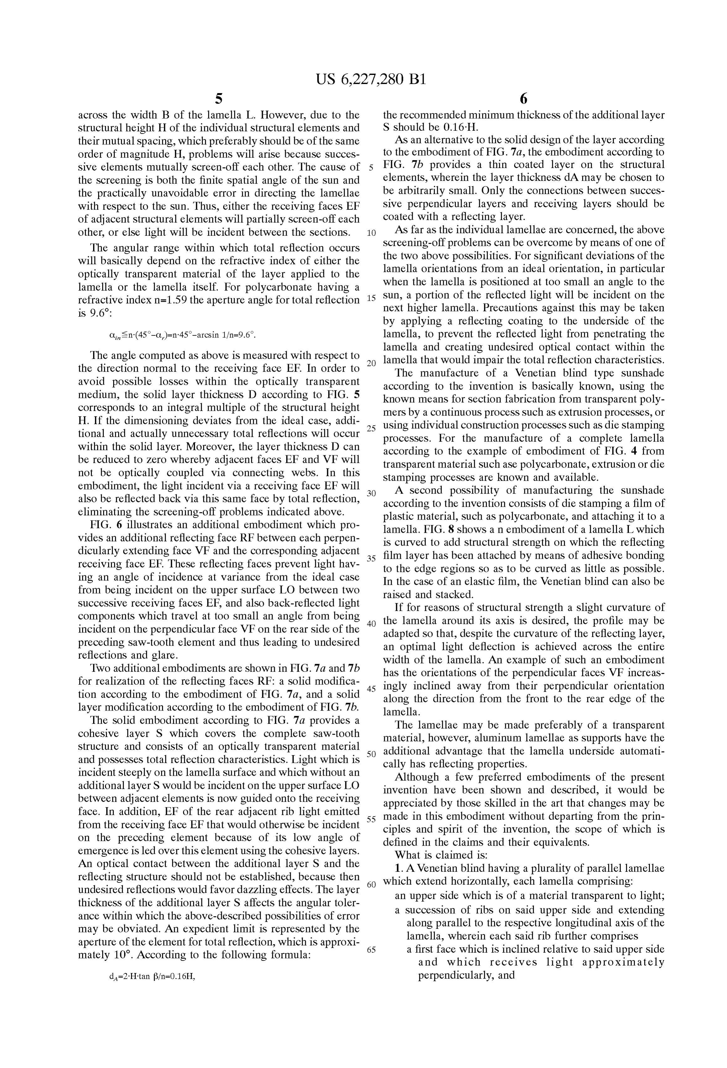
other, or else light will be incident between the Sections. AS far as the individual lamellae are concerned, the above The angular range within which total reflection occurs Screening-off problems can be overcome by means of one of will basically depend on the refractive index of either the the two above possibilities. For significant deviations of the optically transparent material of the layer applied to the lamella orientations from an ideal orientation, in particular lamella or the lamella itself. For polycarbonate having a when the lamella is positioned at too small an angle to the refractive index n=1.59 the aperture angle for total reflection 15 Sun, a portion of the reflected light will be incident on the next higher lamella. Precautions against this may be taken
by applying a reflecting coating to the underSide of the ip - lamella, to prevent the reflected light from penetrating the lamella and creating undesired optical contact within the
The angle computed as above is measured with respect to lamella that would impair the total reflection characteristics. the direction normal to the receiving face EF. In order to The manufacture of a Venetian blind type Sunshade avoid possible losses within the optically transparent according to the invention is basically known, using the medium, the solid layer thickness D according to FIG. 5 known means for Section fabrication from transparent poly corresponds to an integral multiple of the Structural height mers by a continuous process Such as extrusion processes, or H. If the dimensioning deviates from the ideal case, addi using individual construction processes Such as die Stamping tional and actually unnecessary total reflections will occur 25 processes. For the manufacture of a complete lamella within the solid layer. Moreover, the layer thickness D can according to the example of embodiment of FIG. 4 from be reduced to zero whereby adjacent faces EF and VF will transparent material Such ase polycarbonate, extrusion or die not be optically coupled via connecting webs. In this Stamping processes are known and available. embodiment, the light incident via a receiving face EF will A Second possibility of manufacturing the Sunshade also be reflected back via this same face by total reflection, according to the invention consists of die Stamping a film of eliminating the Screening-off problems indicated above. plastic material, Such as polycarbonate, and attaching it to a FIG. 6 illustrates an additional embodiment which pro lamella. FIG. 8 shows an embodiment of a lamella L which vides an additional reflecting face RF between each perpen is curved to add structural Strength on which the reflecting dicularly extending face VF and the corresponding adjacent 35 film layer has been attached by means of adhesive bonding receiving face EF. These reflecting faces prevent light hav to the edge regions So as to be curved as little as possible. ing an angle of incidence at variance from the ideal case In the case of an elastic film, the Venetian blind can also be from being incident on the upper Surface LO between two raised and Stacked.
Successive receiving faces EF, and also back-reflected light components which travel at too small an angle from being 40 theIflamella for reasons of Structural Strength a slight curvature of around its axis is desired, the profile may be incident on the perpendicular face VF on the rear side of the adapted So that, despite the curvature of the reflecting layer, preceding Saw-tooth element and thus leading to undesired an optimal light deflection is achieved across the entire reflections and glare. width of the lamella. An example of such an embodiment Two additional embodiments are shown in FIG. 7a and 7b has the orientations of the perpendicular faces VF increas for realization of the reflecting faces RF: a solid modifica 45 ingly inclined away from their perpendicular orientation tion according to the embodiment of FIG. 7a, and a solid along the direction from the front to the rear edge of the layer modification according to the embodiment of FIG.7b. lamella.
The Solid embodiment according to FIG. 7a provides a The lamellae may be made preferably of a transparent cohesive layer S which covers the complete saw-tooth material, however, aluminum lamellae as Supports have the Structure and consists of an optically transparent material 50 additional advantage that the lamella underside automati and possesses total reflection characteristics. Light which is cally has reflecting properties.
incident Steeply on the lamella Surface and which without an Although a few preferred embodiments of the present additional layer S would be incident on the upper surface LO invention have been shown and described, it would be between adjacent elements is now guided onto the receiving appreciated by those skilled in the art that changes may be face. In addition, EF of the rear adjacent rib light emitted 55 made in this embodiment without departing from the prin from the receiving face EF that would otherwise be incident ciples and Spirit of the invention, the Scope of which is on the preceding element because of its low angle of defined in the claims and their equivalents. emergence is led over this element using the cohesive layers. What is claimed is:
An optical contact between the additional layer S and the 1. A Venetian blind having a plurality of parallel lamellae reflecting Structure should not be established, because then 60 which extend horizontally, each lamella comprising: undesired reflections would favor dazzling effects. The layer an upper Side which is of a material transparent to light; thickness of the additional layer S affects the angular toler a Succession of ribs on Said upper Side and extending ance within which the above-described possibilities of error along parallel to the respective longitudinal axis of the may be obviated. An expedient limit is represented by the lamella, wherein each Said rib further comprises aperture of the element for total reflection, which is approxi 65 a first face which is inclined relative to Said upper Side mately 10. According to the following formula: and which receives light approximately perpendicularly, and
Page 8
a Second face abutting the first face and approximately tive Surfaces wherein each said intermediate reflective Sur perpendicular to Said upper Side, and face is disposed between adjacent reflective elements a third face below and approximately perpendicular to wherein each Said intermediate reflective Surface reflects the Second faces, both light incident to Said upper Side between said adjacent wherein a height of Said Succession of ribs above Said reflective elements and internally reflected light received upper side and a thickness between Said upper Side and from one of said plurality of reflective elements incident to Said third face is Such that light received by Said Said intermediate reflective Surface without causing Substan Succession of ribs penetrates the first faces, is received tial glare.
by said third face to be reflected by said third face, and 12. A Venetian blind having a plurality of lamellae, with is received by the second faces to be reflected out of the each lamella having a Surface Structure, comprising: lamella through the receiving first faces. an upper Side;
2. The Venetian blind according to claim 1, wherein the thickneSS is an integral multiple of the height. a plurality of reflection elements on Said upper Side, and 3. The Venetian blind according to claim 1, wherein the an optically transparent coatings, first and Second faces of each Said rib are slightly curved. 15 wherein 4. The Venetian blind according to claim 1, wherein each Said plurality of reflection elements use internal reflec Said rib further comprises a fourth face which is disposed tions to reflect away received light to Substantially between adjacent ribs and is reflective, wherein the fourth reduce glare while Substantially permitting through faces prevent light received between adjacent ribs from View through Said plurality of lamellae along a being incident on Said upper Side between adjacent ribs, and horizontal direction, prevent light which leaves the lamella through the first faces the Surface Structure further comprises a plurality of from being incident on the Second faces of adjacent ribs. intermediate reflective Surfaces wherein each Said 5. The Venetian blind according to claim 1, further intermediate reflective Surface is disposed between comprising a layer of optically transparent material wherein adjacent reflective elements wherein each Said inter the layer of optically transparent material covers and follows 25 mediate reflective surface reflects both light incident the contour of Said upper Side and Said Succession of ribs to Said upper Side between Said adjacent reflective without materially interfering with the total reflection char elements and internally reflected light received from acteristics of Said Succession of ribs. one of Said plurality of reflective elements incident to 6. The Venetian blind according to claim 1, wherein each Said intermediate reflective Surface without causing lamella has an underside which has a reflective a portion Substantial glare, and wherein the reflective portion reflects light received by the Said optically transparent coating which covers the underside without optically interfering with the total reflec Surface Structure wherein Said optically transparent tion characteristics of Said Succession of ribs and Said third coating guides the light incident to Said intermediate face. reflective Surface onto one of the adjacent reflective 7. A Venetian blind having a plurality of lamellae, with 35 elements, and leads internally-reflected light each lamella having a Surface Structure, comprising: received from one of said plurality of reflective an upper Side, and elements incident to Said intermediate reflective Sur a plurality of reflection elements on Said upper Side; face over one of the adjacent reflective elements. wherein Said plurality of reflection elements use internal 13. A Venetian blind having a plurality of lamellae, with reflections to reflect away received light to Substantially 40 each lamella having a Surface Structure, comprising: reduce glare while Substantially permitting through an upper Side;
View through said plurality of lamellae along a hori a plurality of reflection elements on Said upper Side, and Zontal direction, and a coating, wherein each pair of adjacent reflective elements defines wherein a mutual spacing between the adjacent reflective 45 Said plurality of reflection elements use internal reflec elements, wherein the mutual spacing is approximately tions to reflect away received light to Substantially the equal to the height of the adjacent reflective ele reduce glare while Substantially permitting through ments above the upper Side, and the thickness of the View through Said plurality of lamellae along a adjacent reflective elements below Said upper Side is an horizontal direction, integral multiple of the height. 50 the Surface Structure further comprises a plurality of 8. The Venetian blind of claim 7, where each said reflec intermediate reflective Surfaces wherein each Said tion element further comprises intermediate reflective Surface is disposed between a transmission Surface which receives light into the Sur adjacent reflective elements wherein each Said inter face Structure, and transmits internally reflected light mediate reflective surface reflects both light incident away from the Surface Structure, and 55 to Said upper Side between Said adjacent reflective reflection Surfaces which receive light from the transmis elements and internally reflected light received from Sion Surface, and provide internally reflected light to one of Said plurality of reflective elements incident to one of a plurality of transmission Surfaces of the Said intermediate reflective Surface without causing plurality of Said reflection elements. Substantial glare, and 9. The Venetian blind of claim 8, wherein each transmis 60 Said coating which covers each Said intermediate Sion Surface transmits internally reflected light correspond reflective Surface wherein Said coating guides the ing to the light received by a same transmission Surface. light incident to Said intermediate reflective Surface 10. The Venetian blind of claim 7, wherein the lamella onto one of the adjacent reflective elements, and further comprise an underSide which further comprises a leads internally-reflected light received from one of reflective portion. 65 Said plurality of reflective elements incident to Said 11. The Venetian blind of claim 7, wherein the Surface intermediate reflective Surface over one of the adja Structure further comprises a plurality of intermediate reflec cent reflective elements.
Page 9
14. A Venetian blind comprising: 15. The Venetian blind according to claim 14, wherein the a plurality of parallel lamellae which extend horizontally thickness is an integral multiple of the height. having respective longitudinal axes, each Said lamella 16. The Venetian blind according to claim 14, wherein the comprising first and Second faces of each Said rib are slightly curved. an upper Side which is of a material transparent to light, 17. The Venetian blind according to claim 14, wherein a Succession of parallel ribs on Said upper Side and each rib further comprises a fourth face which is disposed extending along parallel to the respective longitudi nal axis of Said lamella, wherein each Said rib further between adjacent ribs and is reflective, wherein the fourth comprises faces prevent light received between adjacent ribs from a first face which is inclined relative to the upper side being incident on the upper Side between adjacent ribs, and and which receives light approximately prevent light which leaves Said lamella through the first perpendicularly, and faces from being incident on Second faces of adjacent ribs. a Second face abutting the first face and approxi 18. The Venetian blind according to claim 14, further mately perpendicular to the upper Side, and comprising a layer of optically transparent material wherein a third face below and approximately perpendicular 15 the layer of optically transparent material covers and follows to the Second faces, and the contour of the Succession of ribs and the upper Side and a drive mechanism which orients Said plurality of does not materially interfere with the total reflection char parallel lamella about the respective longitudinal acteristics of the Succession of ribs.
axes in order to have the first face receive light approximately perpendicularly; 19. The Venetian blind according to claim 14, wherein wherein a height of Said Succession of ribs above the each Said lamella has an underside further comprising a upper Side and a thickness between the upper Side and reflective portion wherein the reflective portion prevents the third face is Such that light received by the Succes light received by the underSide from optically interfering Sion of ribs penetrates the first faces, is received by the 25 with the total reflection characteristics of the Succession of third face to be reflected by the third face, and is ribs and the third face.
received by the second faces to be reflected out of said lamella through the receiving first faces.
Provenance
- Collection
- Cited prior art
- Original PDF
- patentimages.storage.googleapis.com →
- Filed
- 1997-12-23
- Pages
- 9
- Method
- pdftotext (the PDF's own text layer) + pdftoppm 300dpi page scans
- Source
- Google Patents bibliographic record
- Granted
- 2001-05-08
- Inventors
- Harry Wirth; Andreas Gombert; Volker Willwer; Jörg Jungjohann; Fraunhofer Gesellschaft zur Foerderung der Angewandten Forschung eV
- Transcribed from
- patentimages.storage.googleapis.com →