patent · US4069812
Solar concentrator and energy collection system
24 January 1978
Page 1 — bibliographic record
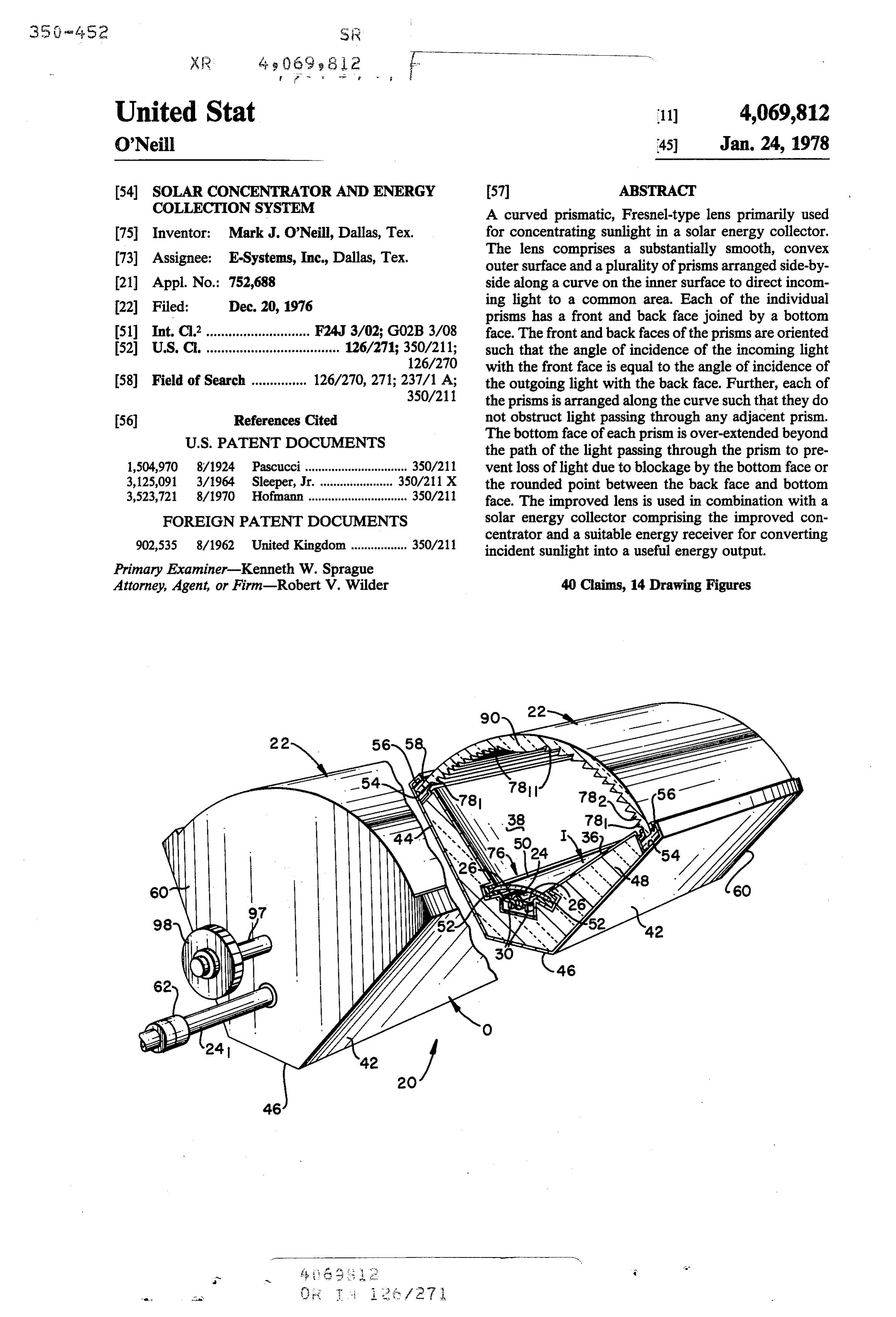
United Stat 11) 4,069,812 O'Neil 45) Jan. 24, 1978 54). SOLAR CONCENTRATOR AND ENERGY 57 ABSTRACT COLLECTION SYSTEM A curved prismatic, Fresnel-type lens primarily used 75 Inventor: Mark J. O'Neill, Dallas, Tex. for concentrating sunlight in a solar energy collector. 73) Assignee: E-Systems, Inc., Dallas, Tex. The lens comprises a substantially smooth, convex outer surface and a plurality of prisms arranged side-by (21) Appl. No.: 752,688 side along a curve on the inner surface to direct incom (22 Filed: Dec. 20, 1976 ing light to a common area. Each of the individual prisms has a front and back face joined by a bottom 51) Int. Cl? ............................ F24J 3/02; G02B 3/08 face. The front and back faces of the prisms are oriented 52 U.S. C. .................................... 126/271; 350/211; such that the angle of incidence of the incoming light 126/270 with the front face is equal to the angle of incidence of 58) Field of Search ............... 126/270, 271; 237/1 A; the outgoing light with the back face. Further, each of 350/211 the prisms is arranged along the curve such that they do 56) References Cited not obstruct light passing through any adjacent prism.
the path of the light passing through the prism to pre 1,504,970 8/1924 Pascucci............................... 350/211 vent loss of light due to blockage by the bottom face or 3,125,091 3/1964 Sleeper, Jr. ... 350/211 X the rounded point between the back face and bottom 3,523,721 8/1970 Hofmann .............................. 350/211 face. The improved lens is used in combination with a FOREIGN PATENT DOCUMENTS solar energy collector comprising the improved con
centrator and a suitable energy receiver for converting incident sunlight into a useful energy output.
Primary Examiner-Kenneth W. Sprague
Attorney, Agent, or Firm-Robert V. Wilder 40 Claims, 14 Drawing Figures
Page 2
Drawing sheet — no readable text.
Page 3
Drawing sheet — no readable text.
Page 4
Drawing sheet — no readable text.
Page 5
Drawing sheet — no readable text.
Page 6
Drawing sheet — no readable text.
Page 7
tial of converting the sun's energy into a useful form of
SOLAR CONCENTRATOR AND ENERGY energy. The loss of 10 or 20% of the energy transmitted COLLECTION SYSTEM through the lens is often times critical as to whether the
BACKGROUND
system may be used for merely heating purposes or for 5 conversion of light into energy useful for air condition
Heretofore, Fresnel lenses have been of two types, a ing, generation of electricity, or other processes. In the flat type and a curved convex type. A three-dimensional past, the flat plate collectors have been used due to the or spherical Fresnel lens is designed to focus on a point, simplicity of construction. However, flat plate collec and a two-dimensional or cylindrical lens is designed to tors need a large area and a large heat absorber, and focus on a line. 10 have very low collection efficiencies. Heat absorbers Previously, Fresnel lenses have been primarily de are often constructed from stainless steel or copper to signed for use with a point source of light to create a minimize corrosion and are therefore extremely expen wide collimated beam of light such as those used in a sive to manufacture.
lighthouse or studio stagelight. Fresnel lenses in use now have a high loss of light An example of the beam focusing lens is disclosed in 15 transmittance through the lens due primarily to reflec the patent to Pascucci, U.S. Pat. No. 1,504,970, which tions at the prism surfaces. This high reflection loss discloses a Fresnel lens having on one face concentric causes a large decrease in collection efficiency. zones united by miters, the miters being cut whereby Therefore, it is highly desirable to produce a solar they are parallel to the path of the rays passing through concentrator which has the highest transmittance and the lens. The juncture of the miters between the bottom 20 the shortest possible focal length. Such a concentrator face and the rear face of the prism is assumed to be a will achieve the highest collection efficiency at mini perfectly pointed configuration. However, in the manu mum cost. The new concentrator described below has facture of these types of lenses out of material such as these beneficial characteristics. glass or acrylic plastics the surface tension of the mate SUMMARY rial placed in the mold at the juncture of these faces will 25 cause the point to be rounded. If the mitered face is I have devised a new curved prismatic Fresnel-type constructed, as taught by Pascucci, and aligned parallel lens for use in a solar energy collector. Generally, the to the path of the rays, and if the lens is used to focus collector comprises a housing of insulating material sunlight, the rounded point will cause divergence of the having an energy receiver positioned at the bottom of light rays along that portion away from the focal point 30 the housing and the prismatic lens secured across the as the light passes through the prism. In addition, errors open top of the housing to direct light toward the en occur in manufacturing the prisms and in aiming of the ergy receiver which may be a heat absorber or other lens toward the sun. These errors will cause a portion of device such as a photovoltaic cell. the light to intercept the bottom face and thus refract The lens comprises a substantially smooth, convex away from the focal point. The loss due to light striking 35 outer surface having a plurality of prisms arranged side the rounded corner and bottom face could be anywhere by side along the curved inner surface of the lens to from 20% when the lens is glass to 5 to 10% when the direct the parallel incoming sunlight to a common area lens is an extruded plastic type lens. or target coinciding with the energy absorber. Fresnel lenses have been used in solar collectors as Each of the individual prisms has a front and back disclosed by the patent to Sleeper, U.S. Pat. No. face joined by a bottom face. The front and back faces 3,125,091, which discloses an inflatable cylindrical type of the prisms are oriented on each prism such that the lens having prisms formed therein. angle of incidence of the incoming light on the front Prisms in the Sleeper patent are superimposed on a face of the prism is equal to the angle of incidence of the circular arc which imposes restrictions on the optical outgoing light on the back face of the prism. The equal efficiency of this type of lens. The light passing through 45 angles of incidence minimize the reflection loss of the the edges of this type of circular lens is so severely light components and therefore affords the highest deflected that it is completely lost. In addition, the transmittance of light through each of the prisms and Sleeper collector teaches a flexible type solar collector therefore through the lens. Each prism is further ar which is incapable of reaching high temperatures and ranged so as not to block the light passing through the withstanding exterior weather conditions for 20 years 50 adjacent prism, and the bottom face of each prism is On Oe, over extended to a position beyond the path of light Heretofore, most prior art Fresnel lenses had longer passing within the prism to a position short of the path focal lengths with F-numbers of 1.0 or greater. This of the light passing out of adjacent prisms to compen required more material, more insulation and a greater sate for aiming errors and rounded points between the volumne of space to construct the lens and solar collec 55 bottom and back faces of the prism. tor to collect the proper amount of heat. Furthermore, The lens has a higher light transmittance than any much of the material content (and thus the cost) of the other lens with the same F-number and material compo collector is due to the housing and structural support sition. The lens can be designed with an F-number system, which can be greatly reduced by reducing the (focal length divided by width) of significantly less than lens focal length to make a more compact collector unit. 60 1.0 such that the overall depth of the units is thus mini Unfortunately, conventional Fresnel-type lenses suffer mized to reduce the materials needed to build the col great losses in transmittance as the focal length is re lectors. The shorter focal length of the lens reduces the duced. This is the reason that prior-art Fresnel lens effect of errors in aiming. The lens is capable of use in a collectors have utilized long focal length lenses with line-focus collector to produce temperatures of up to F-Numbers (focal length divided by lens width) of 1.0 65 500 F, and can be designed in a point-focus collector to or greater. produce temperatures up to 1,000 F. It should be readily apparent that solar collectors The primary object of the invention is to produce a must be highly efficient in order to utilize the full poten prismatic lens for use in solar collectors which mini

Page 8
mizes reflective losses as the light passes through the new lens with an F-number of 0.5, for three different individual prisms of the lens thereby maximizing trans solar collectors.
mittance of light therethrough. DESCRIPTION OF A PREFERRED A further object of the invention is to provide a pris EMBODIMENT matic type lens having a high efficiency and which has 5 a shorter focal length capable of having F-numbers less Referring to FIGS. 1 and 2 of the drawings, the col than 1.0. lector 20 is utilized to concentrate light energy by use of A still further object of the invention is to produce a a prismatic linear lens 22. The linear lens 22 directs the collector which is capable of producing the maximum incoming sunlight to a common focal area 76 generally amount of energy for a minimal amount of space and 10 lying in the focal plane of the linear lens 22. It is general which is lightweight for use on roofs without exces practice to use an energy receiving means which coin sively loading the support structure and which is capa cides with the common focal area of linear lens 22 to ble of producing a highly efficient energy collection convert light energy to heat for various uses. In a solar device. collector the energy receiving means is generally an A still further object of the invention is to produce a 15 absorber such as the one illustrated in FIGS. 1 and 3 lens having individual prisms which are over extended comprising a hollow elongated tube 24 having fins 26 beyond the path of light within said prisms to reduce diametrically secured thereto which may be coated the effect of errors in manufacturing the lens and in with dark coating such as chrome black to more effi aiming the lens toward the sun, and to prevent light 20 ciently absorb sunlight. Tube 24 has a passage 28 losses due to blockage by the rounded point between through which a heat exchange medium flows to absorb the back and the bottom face of the prisms. heat.
A still further object of the invention is to provide an The tube 24 may be resting on spacers 30 which space energy collector which maximizes energy concentra the tube 24 off of the interior housing. The housing tion along an energy receiver by a lens constructed of 25 comprises a generally truncated V-shaped inner hous prisms having front and back surfaces which have equal ing I having sidewalls 36 and 38 which are joined by an angles of incidence with the light passing therethrough. inner bottom 40 which are spaced from outer housing Other and further objects of the invention will be walls 42 and 44 and bottom 46. A layer of thermal insu come apparent upon referring to the detailed descrip lation 48 is positioned between the inner housing I and tion hereinafter following and by referring to the draw- 30 outer housing O to prevent transfer of heat away from ings annexed hereto. the energy receiving means. The insulation 48 may be DESCRIPTION OF DRAWINGS fiberglass or some other suitable type. A clear, con caved transparent cover 50 is positioned over the upper
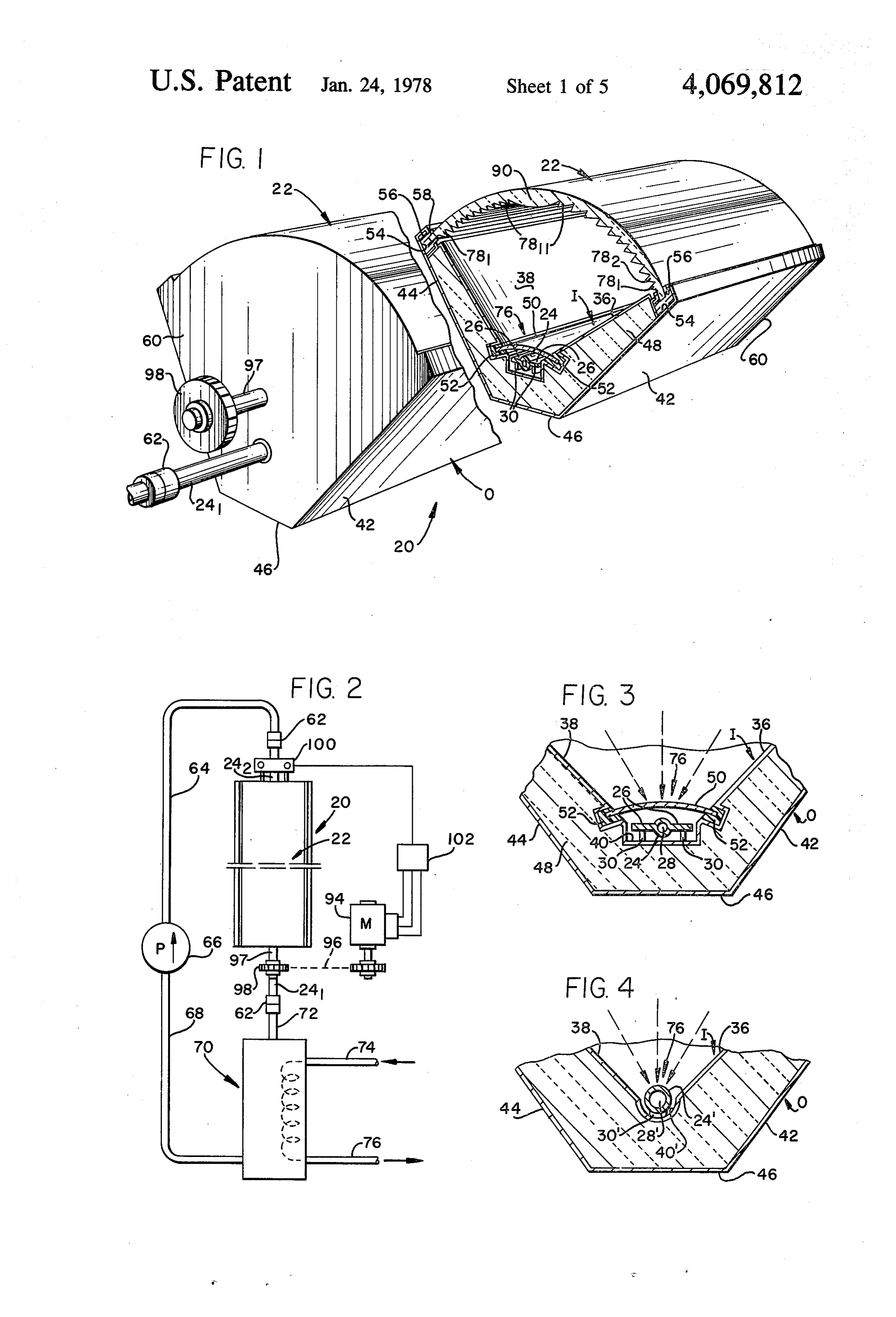
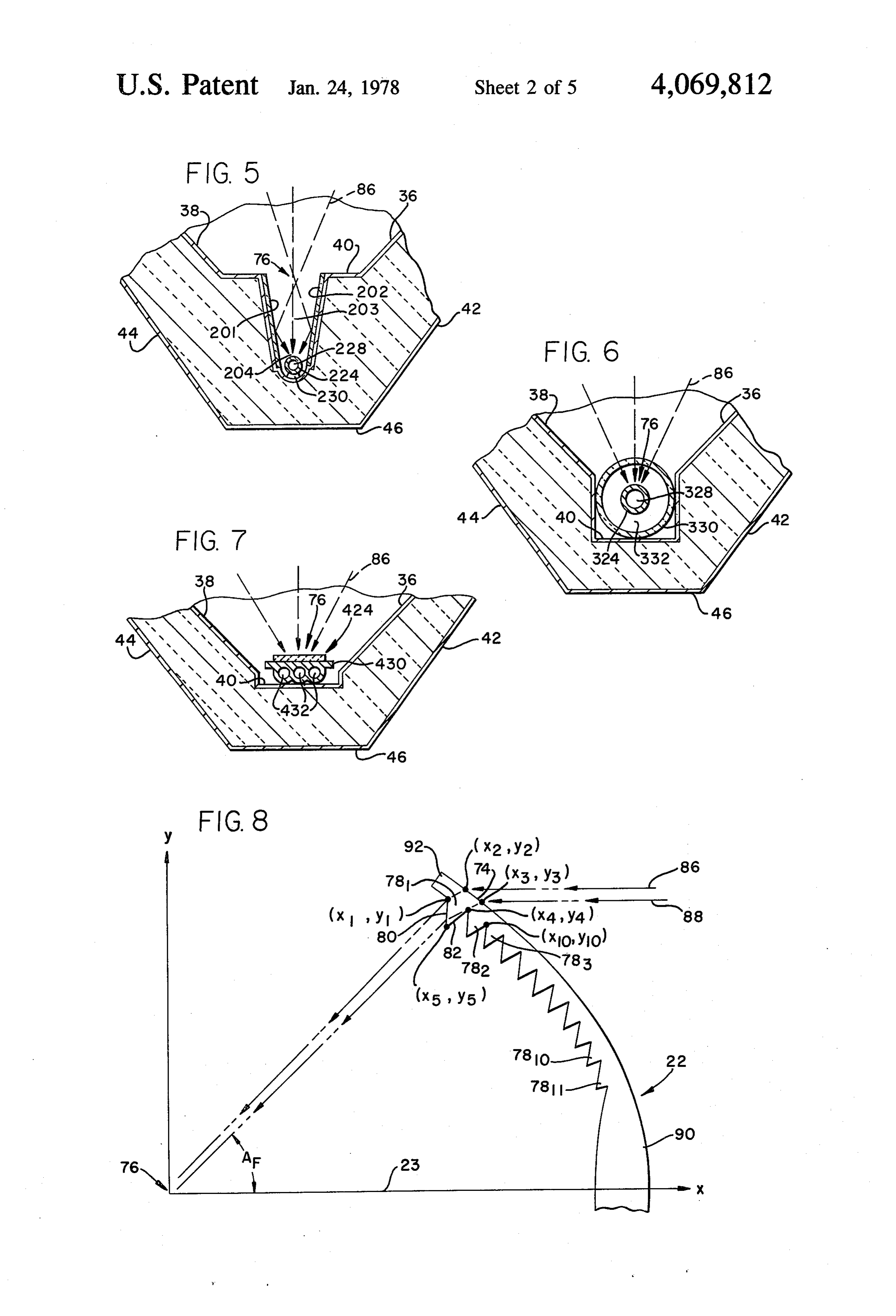
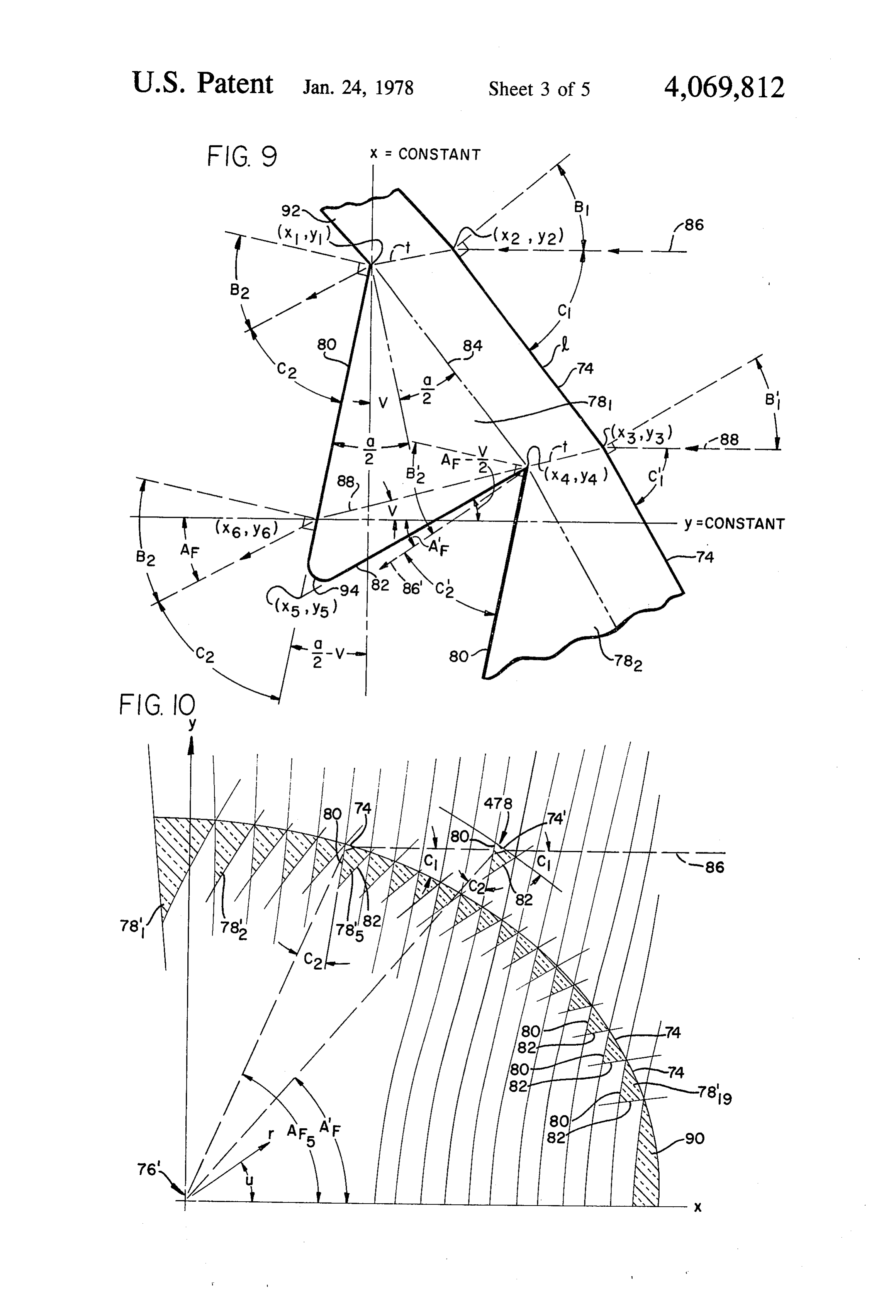
Drawings of preferred embodiments of the invention side of tube 24 in longitudinal passages 52 formed in the lower end of sidewalls 36 and 38 to decrease heat loss are annexed hereto so that the invention may be better is from and more fully understood, in which: the receiver tube 24.
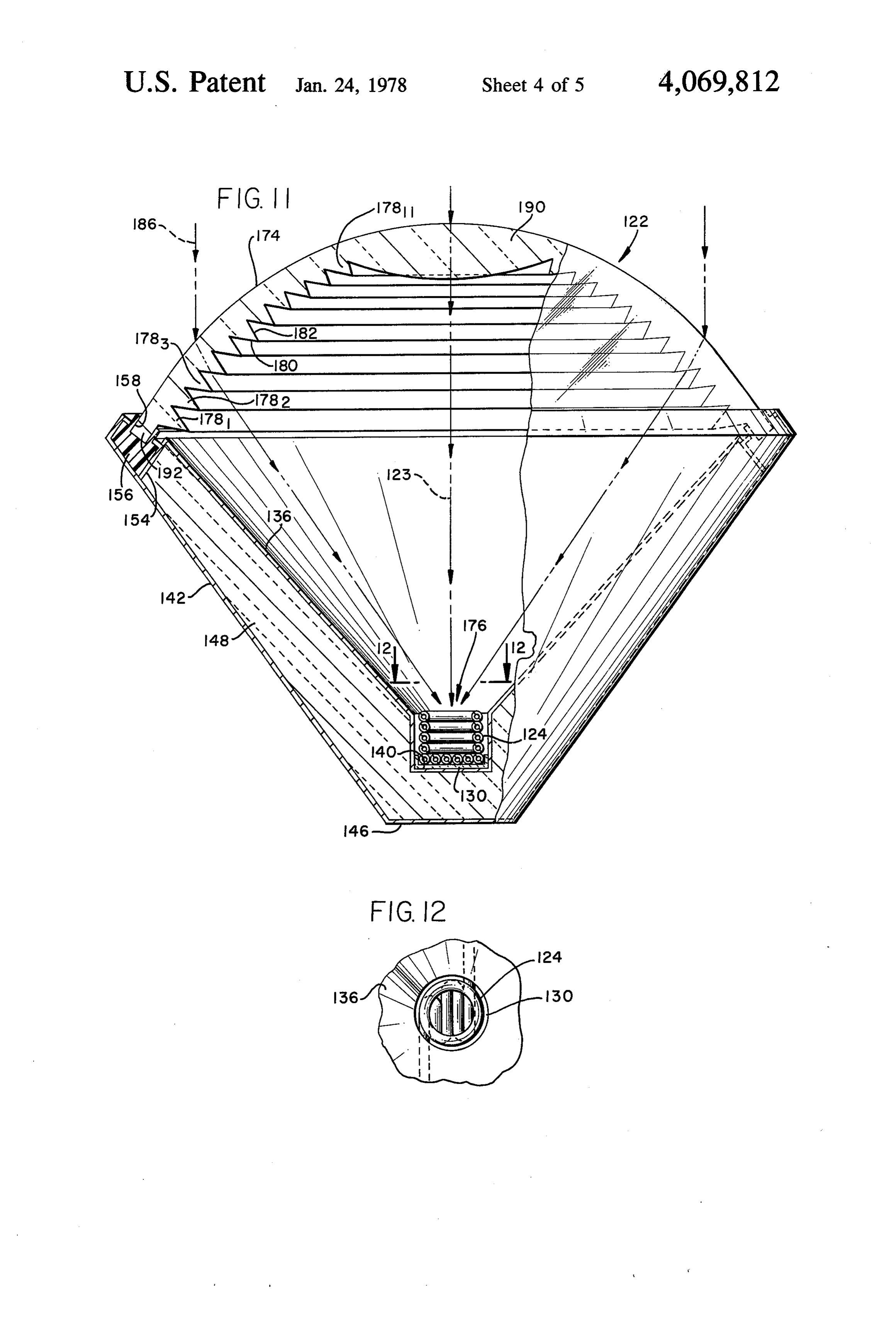
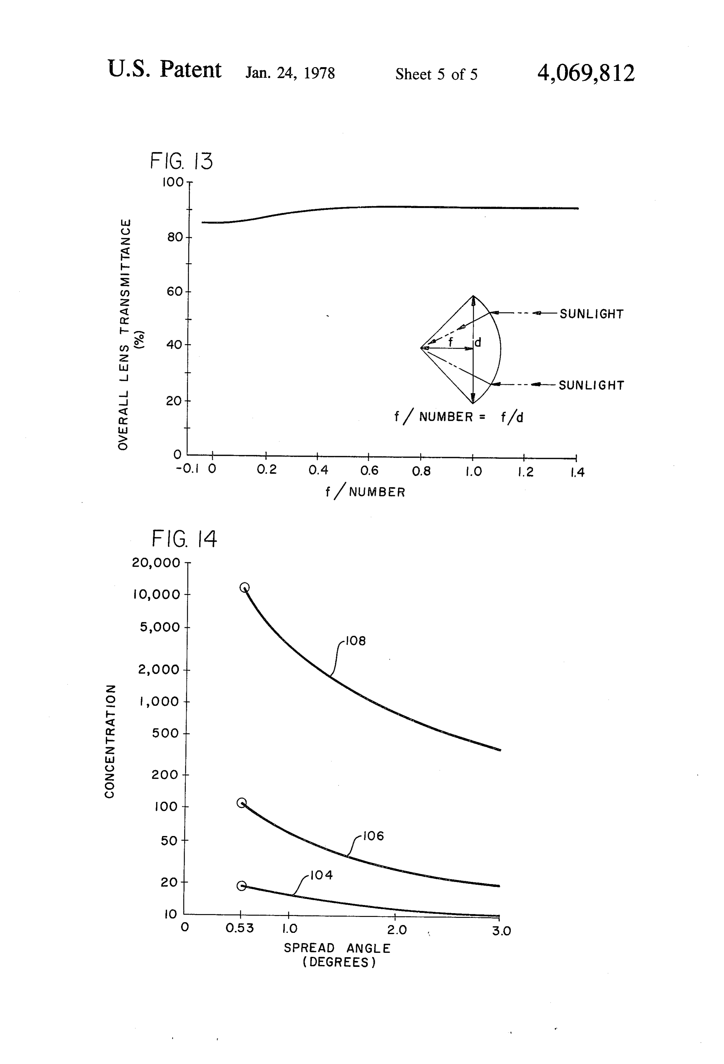
FIG. 1 is a perspective view with parts broken away A C-shaped channel 54 is formed at the upper end of to more clearly illustrate the details of construction of the outer housing sidewall 42 and 44 and joined with the the collector; inner housing sidewalls 36 and 38, respectively, to con FIG. 2 is a diagrammatic view illustrating a typical 40 nect the tops together. The channel 54 runs longitudi solar concentrator; nally along the sidewalls of the collector 20. A resilient FIG. 3 is an enlarged cross-sectional view of the gasket 56 having a slot 58 for receiving the edges of lens energy receiver; 22 is disposed longitudinally in C-shaped channel 54. FIG. 4 is an enlarged cross-sectional view of a first The gasket 56 provides a weather tight seal to protect modified form of the energy receiver illustrated in FIG. 45 the collector 20 interior from rain, dust and corrosion. 3; End panels 60 are positioned across each end of the FIG. 5 is an enlarged cross-sectional view of a second inner housing sidewalls 36 and 38 and outer housing modified form thereof; sidewalls 44 and 42 to seal and insulate the collector 20. FIG. 6 is an enlarged cross-sectional view of a third Tube 24 passes outwardly from the lower end of end modified form thereof; 50 panels 60. Tube 241 can be a flexible hose to allow the FIG. 7 is an enlarged cross-sectional view of a fourth collector 20 to rotate with sprocket 98 to track the sun. modified form thereof; As best illustrated in FIG. 2, the connection 62 on the FIG. 8 is a partial end elevational view of the lens end of tube 24 is attached to pipe 64 which is connected disconnected from the collector; to the outlet of pump 66. The pipe 68 is connected FIG. 9 is an enlarged end view of the left outermost 55 between the inlet of pump 66 and the outlet of heat prism of the lens illustrated in FIG.8; exchanger 70 having an inlet. Pipe 72 is connected be FIG. 10 is a graph diagrammatically illustrating an tween the inlet of exchanger 70 and flexible tube 24. A end view of the lens constructed by polar coordinates; heat exchange medium is pumped through pipe 64 and FIG. 11 is an elevational view of a modified form of 68 and through tube 24 of collector 20 for heating the the collector with parts broken away to more clearly 60 heat exchanger 70. Heat exchanger 70 has an inlet pipe illustrate the details of construction; 74 and an outlet pipe 76 through which another heat FIG. 12 is a cross-sectional view taken along line exchange medium is passed for connection to apparatus 12-12 of FIG. 11; to use the solar heat collected for air conditioning or FIG. 13 is a graph illustrating the overall transmit other applications. It should be readily apparent that tance of light through the lens for various F-numbers of 65 various types of arrangements for using the heated me the new lens; and dium are possible and are well known in the art and the FIG. 14 is a graph illustrating the concentration of embodiment shown in FIG. 2 is merely an example of light in sun's versus the spread angle of the light for the such an arangement. A typical heat exchange medium is
Page 9
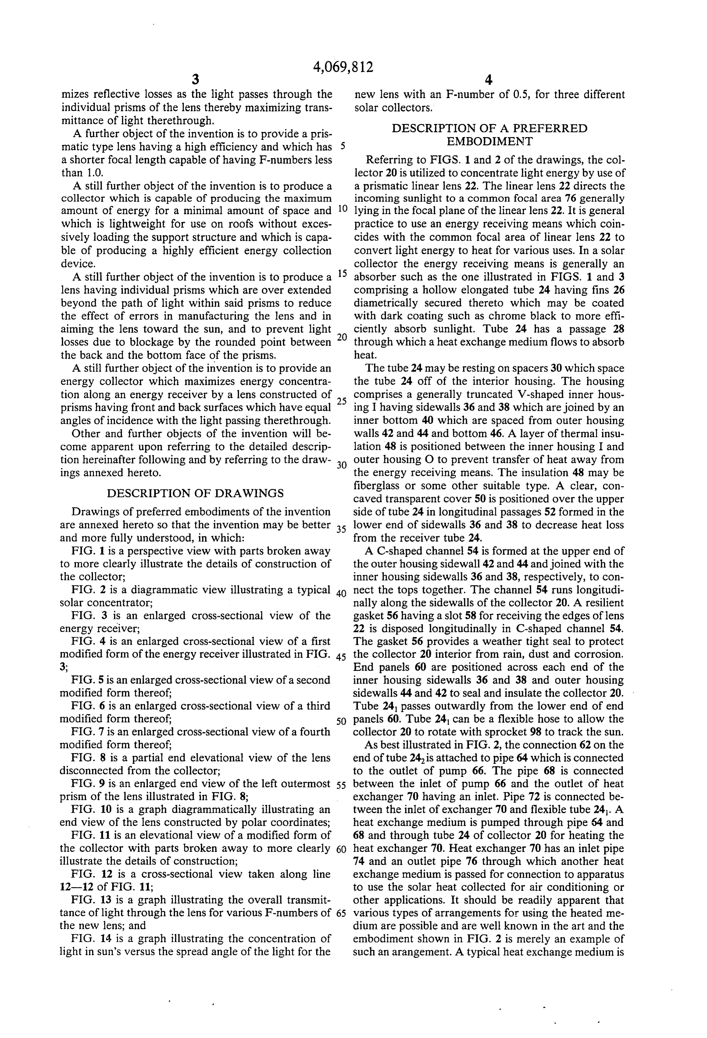
water. The axis of rotation of the collector will usually As will be more fully explained hereinafter, the de be parallel to the Earth's polar axis to facilitate tracking. sign of this lens allows for the maximum transmittance As best illustrated in FIGS. 1, 8, and 9, the prismatic T of energy through the lens while allowing focal linear lens 22 comprises a curved outer surface formed lengths of the lens 22 to be designed having an F-num by the front face 74 of a plurality of prisms 78. Prisms 78 ber in the range of slightly negative to positive infinity. are arranged as shown in FIG. 8 from the outer most The lens 22 has a design such that an F-number of 1.0 or prism 78 to the innermost prism 781. The prisms 78 are less may be produced while maintaining transmittance arranged to focus the light to a common focal area 76 levels of light about 90%. F-number is herein defined as which corresponds to the intersection of the X-Y axes. focal length divided by lens width, for example, x/2y, The inner surface of the lens 22 is defined by the remain O for the lens of FIG. 8, wherein the focal length is the ing surfaces of the plurality of prisms 781-781 each of distance between the focal point and an imaginary which has the front face 74 corresponding to the outer chord passing from one edge of the lens to the other, surface of the lens, a back face 80 and a bottom face 82 such chord passing perpendiculariv through the axis 23. to form a linear prism element 78 which has a substan 15 It should be readily apparent that in actual usage the tially truncated triangular cross-section as best illus prisms 78 would be much smaller and more numerous trated in FIG. 9. As illustrated in FIG.9, the prism base than shown in FIG. 8, to conserve material and to main line 84 shown in dashed outline is parallel to the front tain a light weight lens.
face 74 of lens 22 and has an equal length thereto. It In order to prove that maximum transmittance occurs should be readily apparent that the curved outer surface 20 when angle B1 = angle B, relative to the respective of the lens may be comprised of short, straight sections front face 74 and back face 80, I have formulated the of front face 74 which give the appearance of the following proof:
curved surface. The length of surfaces 74 is ideally Consider the refraction phenomenon for an individ minimized to be as short as practical and may in reality ual prism, wherein:
be actually curved in the construction of lens. B = the angle of incidence at the first prism face, The front face 74 is positioned at an angle B1 with the 25 B = the angle of incidence at the second prism face, incoming parallel rays 86 and 88 of sunlight diagram A = the total turning angle of the light ray, matically illustrated by dashed lines in FIGS. 8 and 9. n = the prism material index of refraction. Each prism 78 is oriented such that the incidence angle From Snell's law, one can show that: (1) A = B1 - B with the incoming light relative to the front face 74 30 sin (sinB/n) -- B - sin (sinB/n). For a thin Fres is equal to the angle of incidence B formed by the out nel lens made of non-absorbing material, such as acrylic going sunlight relative to the back face 80 of the prism plastic, light absorption losses will be small compared to 78 such that eacn prism 78 is oriented along the inner light reflection losses. Furthermore, for non-polarized surface of the lens 22 to refract the light at a specified light such as solar radiation, one can show from basic turning angle A, this angle being an angle between the 35 electromagnetic theory that the single-surface reflec axis 23 of lens 22 and the ray of light 88, to orient the tances for the prism are governed by the following light passing through each of the prisms 78 - 781 to a equations:
common focal area 76 which preferably coincides with the upper surface of the energy receiving means. The sin B - sin(sin B/n) tan’B - sin"(sinB/n) (2) equal angles of incidence B1 and B of the sunlight with the front face 74 and back face 80 as it passes there 2sinB -- sin(sin B/n)) 2tan B, + sin"(sin B/n)) through each prism 78 provide for a maximum light sin' B, - sin(sinB/n)) . tan B, - sin"(sin B/n)) () transmittance and therefore maximum efficiency of the 2tan B, + sin(sin B/n)) lens 22 and collector 20. 2sinB, + sin(sinB/n)
The second prism 78 has a turning angle A" which is 45 slightly less than A. The angles of incidence B1 and B' wherein P = the reflectance at the first prism face, with front face 74 and back face 80 are equal but the and angles have a different value from the angles of inci wherein P = the reflectance at the second prism dence Band B. It should be readily apparent that each face. The overall prism transmittance (T) is; (4) T set of angles change for each prism 78-781 in order to 50 = (1-P) (1-P), assuming no light absorption maximize the transmittance of light therethrough. within the prism. When T is maximized, its differ In the center of lens 22 where the prisms become ential should vanish:
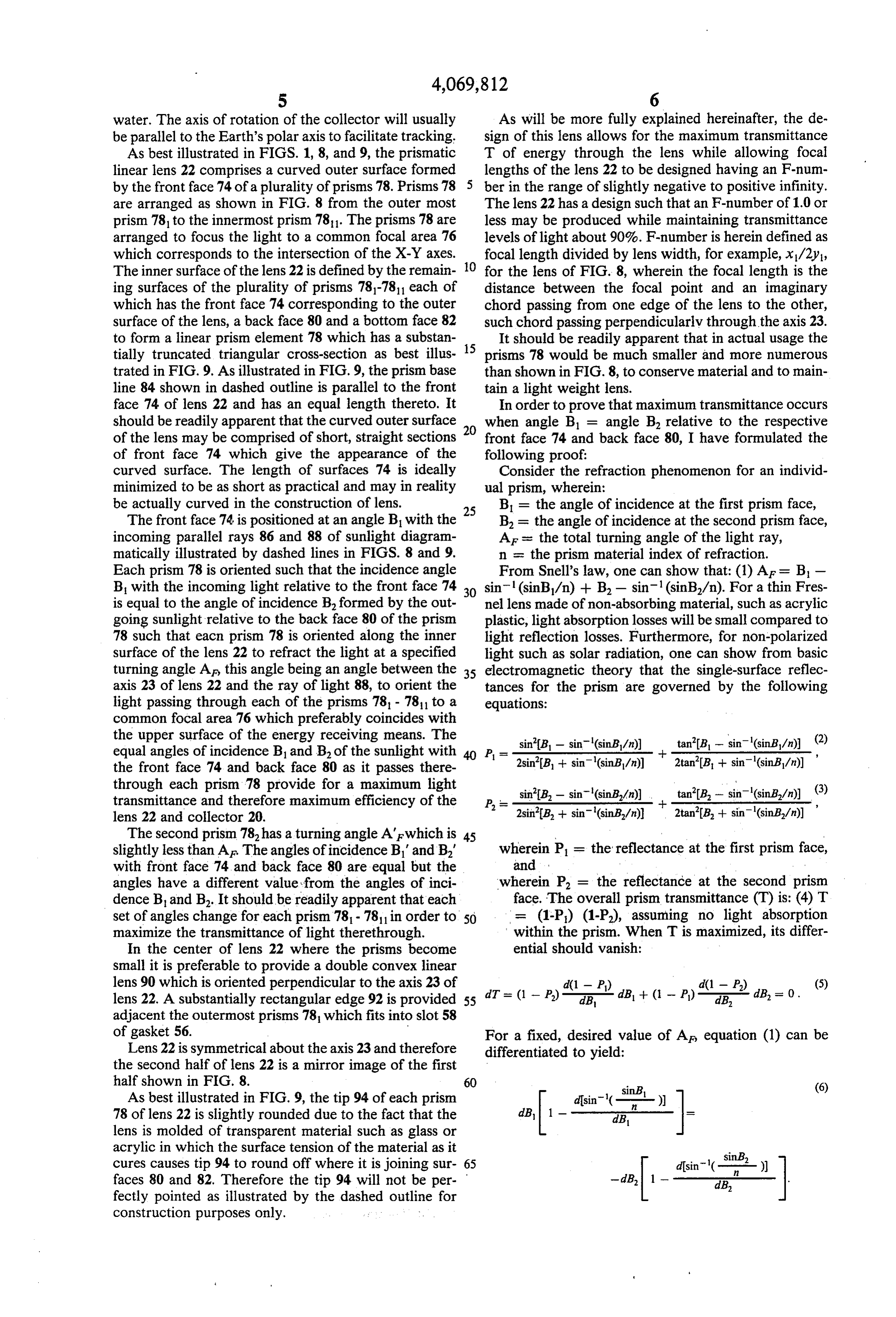
small it is preferable to provide a double convex linear lens 90 which is oriented perpendicular to the axis 23 of d(1 - P) d(1 - P.) (5) lens 22. A substantially rectangular edge 92 is provided 55 dT = (1 - P.) - as dB + ( - P) dB, dB = 0. adjacent the outermost prisms 78 which fits into slot 58 of gasket 56. For a fixed, desired value of A equation (1) can be Lens 22 is symmetrical about the axis 23 and therefore differentiated to yield:
the second half of lens 22 is a mirror image of the first half shown in FIG. 8. 60 (6) As best illustrated in FIG. 9, the tip 94 of each prism 78 of lens 22 is slightly rounded due to the fact that the
lens is molded of transparent material such as glass or acrylic in which the surface tension of the material as it cures causes tip 94 to round off where it is joining sur 65 disin ( sin B, D) faces 80 and 82. Therefore the tip 94 will not be per -dB, 1 - - dB, - fectly pointed as illustrated by the dashed outline for construction purposes only.
Page 10
Now, when B1 = B, equation (6) becomes: (7) dB = - dB. Furthermore, from equations (2) and (3), when --
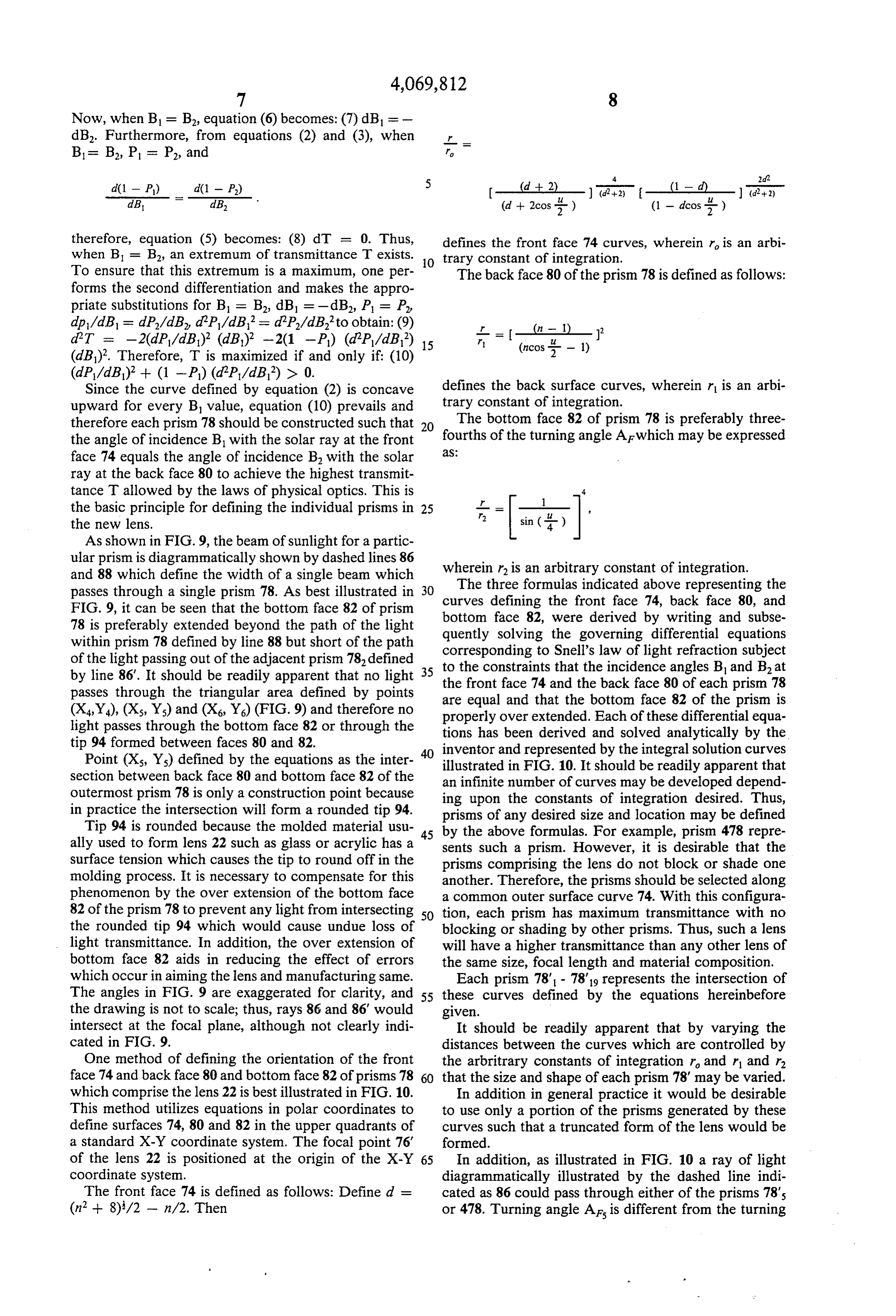
therefore, equation (5) becomes: (8) dT = 0. Thus, defines the front face 74 curves, wherein r is an arbi when B = B, an extremum of transmittance T exists. O trary constant of integration.
To ensure that this extremum is a maximum, one per The back face 80 of the prism 78 is defined as follows: forms the second differentiation and makes the appro priate substitutions for B = B, dB = -dB, P = P, dp/dB = dP/dB dP/dB = d2P/dB to obtain: (9) dT = -2(dP/dB)? (dB)? -2(1 -P) (dPP/dB) 15 r (ncos t - 1) (dB). Therefore, T is maximized if and only if: (10)
Since the curve defined by equation (2) is concave defines the back surface curves, wherein r is an arbi upward for every B1 value, equation (10) prevails and trary constant of integration.
therefore each prism 78 should be constructed such that 20 The bottom face 82 of prism 78 is preferably three the angle of incidence B with the solar ray at the front 2S fourths of the turning angle A which may be expressed face 74 equals the angle of incidence B with the solar ray at the back face 80 to achieve the highest transmit tance T allowed by the laws of physical optics. This is 4.
the basic principle for defining the individual prisms in 25 -- = 1 the new lens. r sin ( )
As shown in FIG. 9, the beam of sunlight for a partic ular prism is diagrammatically shown by dashed lines 86 wherein r is an arbitrary constant of integration. and 88 which define the width of a single beam which passes through a single prism 78. As best illustrated in 30 The three formulas indicated above representing the curves defining the front face 74, back face 80, and
FIG. 9, it can be seen that the bottom face 82 of prism bottom 78 is preferably extended beyond the path of the light quently face 82, were derived by writing and subse solving the governing differential equations within prism 78 defined by line 88 but short of the path corresponding to Snell's law of light refraction subject of the light passing out of the adjacent prism 78 defined to the constraints that the incidence angles B and B at by line 86'. It should be readily apparent that no light 35 the front face 74 and passes through the triangular area defined by points are equal and that thethebottom back face 80 of each prism 78 (X,Y), (X, Y) and (X, Y) (FIG. 9) and therefore no properly over extended. Each offace these 82 of the prism is differential equa light passes through the bottom face 82 or through the tions has been derived and solved analytically by the tip 94 formed between faces 80 and 82. 40 inventor and represented by the integral solution curves Point (X, Y) defined by the equations as the inter illustrated in FIG. 10. It should be readily apparent that section between back face 80 and bottom face 82 of the an infinite number of curves may be developed depend outermost prism 78 is only a construction point because ing upon the constants of integration desired. Thus, in practice the intersection will form a rounded tip. 94. prisms of any desired size and location may be defined Tip 94 is rounded because the molded material usu by the above formulas. For example, prism 478 repre ally used to form lens 22 such as glass or acrylic has a 45 sents such a prism. However, it is desirable that the surface tension which causes the tip to round off in the prisms comprising the lens do not block or shade one molding process. It is necessary to compensate for this another. Therefore, the prisms should be selected along phenomenon by the over extension of the bottom face a common outer surface curve 74. With this configura 82 of the prism 78 to prevent any light from intersecting 50 tion, each prism has maximum transmittance with no the rounded tip 94 which would cause undue loss of blocking or shading by other prisms. Thus, such a lens light transmittance. In addition, the over extension of will have a higher transmittance than any other lens of bottom face 82 aids in reducing the effect of errors the same size, focal length and material composition, which occur in aiming the lens and manufacturing same. Each prism 78' - 78's represents the intersection of The angles in FIG. 9 are exaggerated for clarity, and 55 these curves defined by the equations hereinbefore the drawing is not to scale; thus, rays 86 and 86' would given.
intersect at the focal plane, although not clearly indi It should be readily apparent that by varying the cated in FIG. 9. distances between the curves which are controlled by One method of defining the orientation of the front the arbritrary constants of integration r and r1 and r2 face 74 and back face 80 and bottom face 82 of prisms 78 60 that the size and shape of each prism 78 may be varied. which comprise the lens 22 is best illustrated in FIG. 10. In addition in general practice it would be desirable This method utilizes equations in polar coordinates to to use only a portion of the prisms generated by these define surfaces 74, 80 and 82 in the upper quadrants of curves such that a truncated form of the lens would be a standard X-Y coordinate system. The focal point 76 formed.
of the lens 22 is positioned at the origin of the X-Y 65 In addition, as illustrated in FIG. 10 a ray of light coordinate system. diagrammatically illustrated by the dashed line indi The front face 74 is defined as follows: Define d = cated as 86 could pass through either of the prisms 78's (n + 8)/2 - n/2. Then or 478. Turning angle Aris different from the turning
Page 11
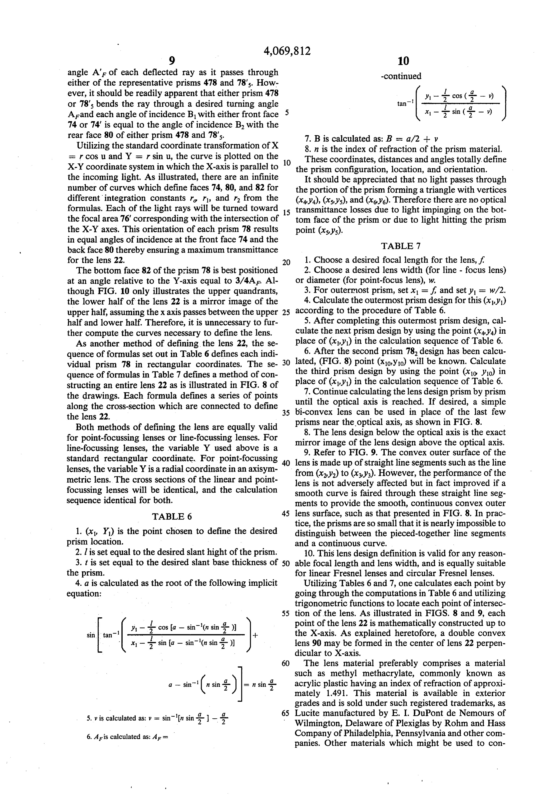
angle AF of each deflected ray as it passes through -continued either of the representative prisms 478 and 78's. How ever, it should be readily apparent that either prism 478 y - cos ( - ) or 78's bends the ray through a desired turning angle tan Arand each angle of incidence B1 with either front face 5 2 sin (; – ) 74 or 74 is equal to the angle of incidence B, with the rear face 80 of either prism 478 and 78's. 7. B is calculated as: B is a/2 -- y Utilizing the standard coordinate transformation of X 8. n is the index of refraction of the prism material. sc rcos u and Y = r sinu, the curve is plotted on the 10 These coordinates, distances and angles totally, define X-Y coordinate system in which the X-axis is parallel to the prism configuration, location, and orientation. the incoming light. As illustrated, there are an infinite It should be appreciated that no light passes through number of curves which define faces 74, 80, and 82 for the portion of the prism forming a triangle with vertices different integration constants r r1, and r2 from the (x,y), (xsys), and (xsys). Therefore there are no optical formulas. Each of the light rays will be turned toward 15 transmittance losses due to light impinging on the bot the focal area 76' corresponding with the intersection of tom face of the prism or due to light hitting the prism the X-Y axes. This orientation of each prism 78 results point (xsys).
in equal angles of incidence at the front face 74 and the TABLE 7 back face 80 thereby ensuring a maximum transmittance for the lens 22. 20 1. Choose a desired focal length for the lens, f. The bottom face 82 of the prism 78 is best positioned 2. Choose a desired lens width (for line - focus lens) at an angle relative to the Y-axis equal to 3/4AF. Al or diameter (for point-focus lens), w.
though FIG. 10 only illustrates the upper quandrants, 3. For outermost prism, set x = f, and set y = w/2. the lower half of the lens 22 is a mirror image of the 4. Calculate the outermost prism design for this (x,y) upper half, assuming the x axis passes between the upper 25 according to the procedure of Table 6. half and lower half. Therefore, it is unnecessary to fur 5. After completing this outermost prism design, cal ther compute the curves necessary to define the lens. culate the next prism design by using the point (x,y) in As another method of defining the lens 22, the se place of (x,y) in the calculation sequence of Table 6. quence of formulas set out in Table 6 defines each indi 6. After the second prism 78 design has been calcu vidual prism 78 in rectangular coordinates. The se 30 lated, (FIG. 8) point (x,y) will be known. Calculate quence of formulas in Table 7 defines a method of con the third prism design by using the point (xio yo) in structing an entire lens 22 as is illustrated in FIG. 8 of place 7.
of (x,y) in the calculation sequence of Table 6.
Continue calculating the lens design prism by prism the drawings. Each formula defines a series of points until the optical along the cross-section which are connected to define 35 bi-convex lens canaxisbeisused reached. If desired, a simple in place of the last few the lens 22.
Both methods of defining the lens are equally valid prisms near the optical axis, as shown in FIG. 8. for point-focussing lenses or line-focussing lenses. For mirror image of the lens design optical 8. The lens design below the above axis is the exact the optical axis.
line-focussing lenses, the variable Y used above is a 9. Refer to FIG. 9. The convex outer surface of the standard rectangular coordinate. For point-focussing 40 lens is made up of straight line segments such as the line lenses, the variable Y is a radial coordinate in an axisym from (x,y) to (x,y). However, the performance of the metric lens. The cross sections of the linear and point lens is not adversely affected but in fact improved if a focussing lenses will be identical, and the calculation smooth curve is faired through these straight line seg sequence identical for both. ments to provide the smooth, continuous convex outer TABLE 6 45 lens surface, such as that presented in FIG.8. In prac tice, the prisms are so small that it is nearly impossible to 1. (xi, Y) is the point chosen to define the desired distinguish between the pieced-together line segments prism location. and a continuous curve.
2. l is set equal to the desired slant hight of the prism. 10. This lens design definition is valid for any reason 3. t is set equal to the desired slant base thickness of 50 able focal length and lens width, and is equally suitable the prism. for linear Fresnel lenses and circular Fresnel lenses. 4. a is calculated as the root of the following implicit Utilizing Tables 6 and 7, one calculates each point by equation: going through the computations in Table 6 and utilizing trigonometric functions to locate each point of intersec 55 tion of the lens. As illustrated in FIGS. 8 and 9, each y --2 cos (a - sin(n sin 2-) point of the lens 22 is mathematically constructed up to sita -1 -- the X-axis. As explained heretofore, a double convex x - 2- sin (a - sin(n sin 2-)) lens 90 may be formed in the center of lens 22 perpen dicular to X-axis.
60 The lens material preferably comprises a material such as methyl methacrylate, commonly known as a - sinn sin 2- ||= n sin 2- acrylic plastic having an index of refraction of approxi mately 1.491. This material is available in exterior grades and is sold under such registered trademarks, as 65 Lucite manufactured by E. I. DuPont de Nemours of 5. y is calculated as: y = sinn sin :- - g Wilmington, Delaware of Plexiglas by Rohm and Hass 6. Aris calculated as: AF = Company of Philadelphia, Pennsylvania and other com panies. Other materials which might be used to con
Page 12
struct this lens would be polystyrene having an index of near-perfect focussing will occur all day. Thus, this refraction of 1.590 or polycarbonate having an index of third and preferred tracking system will vary the re refraction of 1.586 or methacrylate styrene copolymer ceiver position within the collector to maintain it at F sold under the tradename NAS. These materials may be cos D, wherein D is the declination angle. Since the extruded from a die using conventional molding meth 5 declination angle varies slowly, daily or even weekly ods to produce the lens in a linear from or the material corrections of receiver position will suffice to provide may be calendered and bent to the desired curved sur highly accurate focussing. Thus, manual adjustment or face under conventional method of manufacture well automatic adjustment means for receiver location could known in the art. The desired widths of lens 22 would be provided without much additional cost. This track be subject to various factors but may be in a range 10 ing method will provide concentrations equivalent to anywhere from about 1 to 4 feet (30 - 120cm.) and two-directional tracking.
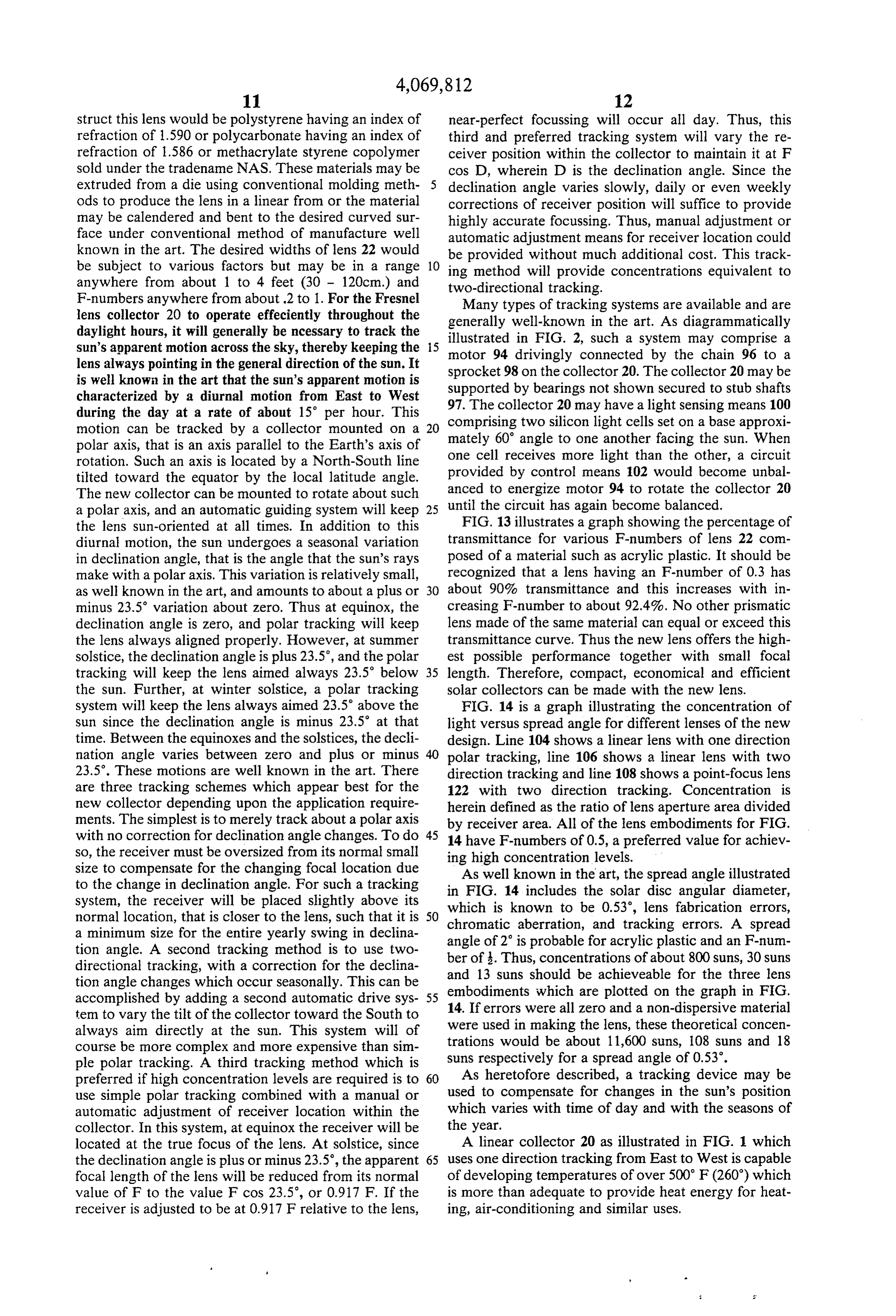
F-numbers anywhere from about .2 to 1. For the Fresnel Many types of tracking systems are available and are lens collector 20 to operate effeciently throughout the generally well-known in the art. As diagrammatically daylight hours, it will generally be ncessary to track the sun's apparent motion across the sky, thereby keeping the 5 illustrated motor 94 in FIG. 2, such a system may comprise a drivingly connected by the chain 96 to a lens always pointing in the general direction of the sun. It sprocket 98 on the collector 20. The collector 20 may be is well known in the art that the sun's apparent motion is supported by bearings not shown secured to stub shafts characterized by a diurnal motion from East to West 97. The collector 20 may have a light sensing means 100 during the day at a rate of about 15 per hour. This comprising two silicon light cells set on motion can be tracked by a collector mounted on a 20 mately 60' angle to one another facing athebase approxi sun. When polar axis, that is an axis parallel to the Earth's axis of one cell receives more light than the other, a circuit rotation. Such an axis is located by a North-South line tilted toward the equator by the local latitude angle. provided by control means 102 would become unbal The new collector can be mounted to rotate about such anced to energize motor 94 to rotate the collector 20 a polar axis, and an automatic guiding system will keep 25 until the circuit has again become balanced. FIG. 13 illustrates a graph showing the percentage of the lens sun-oriented at all times. In addition to this diurnal motion, the sun undergoes a seasonal variation transmittance for various F-numbers of lens 22 com in declination angle, that is the angle that the sun's rays posed of a material such as acrylic plastic. It should be make with a polar axis. This variation is relatively small, recognized that a lens having an F-number of 0.3 has as well known in the art, and amounts to about a plus or 30 about 90% transmittance and this increases with in minus 23.5 variation about zero. Thus at equinox, the creasing F-number to about 92.4%. No other prismatic declination angle is zero, and polar tracking will keep lens made of the same material can equal or exceed this the lens always aligned properly. However, at summer transmittance curve. Thus the new lens offers the high solstice, the declination angle is plus 23.5', and the polar est possible performance together with small focal tracking will keep the lens aimed always 23.5' below 35 length. Therefore, compact, economical and efficient the sun. Further, at winter solstice, a polar tracking solar collectors can be made with the new lens. system will keep the lens always aimed 23.5° above the FIG. 14 is a graph illustrating the concentration of sun since the declination angle is minus 23.5 at that light versus spread angle for different lenses of the new time. Between the equinoxes and the solstices, the decli design. Line 104 shows a linear lens with one direction nation angle varies between zero and plus or minus polar tracking, line 106 shows a linear lens with two 23.5. These motions are well known in the art. There direction tracking and line 108 shows a point-focus lens are three tracking schemes which appear best for the 122 with two direction tracking. Concentration is new collector depending upon the application require herein defined as the ratio of lens aperture area divided ments. The simplest is to merely track about a polar axis by receiver area. All of the lens embodiments for FIG. with no correction for declination angle changes. To do 45 14 have F-numbers of 0.5, a preferred value for achiev so, the receiver must be oversized from its normal small size to compensate for the changing focal location due ingAshigh concentration levels.
to the change in declination angle. For such a tracking in FIG. 14known well in the art, the spread angle illustrated includes the solar disc angular diameter, system, the receiver will be placed slightly above its normal location, that is closer to the lens, such that it is 50 which is known to be 0.53, lens fabrication errors, chromatic aberration, and tracking errors. A spread a minimum size for the entire yearly swing in declina angle of 2 is probable for acrylic plastic and an F-num tion angle. A second tracking method is to use two ber directional tracking, with a correction for the declina and of13 .Suns Thus, concentrations of about 800 suns, 30 suns tion angle changes which occur seasonally. This can be embodimentsshould which be achieveable for the three lens are plotted on the graph in FIG.
accomplished by adding a second automatic drive sys 14. If errors were all zero
and a non-dispersive material tem to vary the tilt of the collector toward the South to always aim directly at the sun. This system will of were used in making the lens, these theoretical concen course be more complex and more expensive than sim trations would be about 11,600 suns, 108 suns and 18 ple polar tracking. A third tracking method which is suns respectively for a spread angle of 0.53. preferred if high concentration levels are required is to 60 As heretofore described, a tracking device may be use simple polar tracking combined with a manual or used to compensate for changes in the sun's position automatic adjustment of receiver location within the which varies with time of day and with the seasons of collector. In this system, at equinox the receiver will be the year.
located at the true focus of the lens. At solstice, since A linear collector 20 as illustrated in FIG. 1 which the declination angle is plus or minus 23.5', the apparent 65 uses one direction tracking from East to West is capable focal length of the lens will be reduced from its normal of developing temperatures of over 500 F (260) which value of F to the value F cos 23.5', or 0.917 F. If the is more than adequate to provide heat energy for heat receiver is adjusted to be at 0.917 F relative to the lens, ing, air-conditioning and similar uses.
Page 13
MODIFIED FORM lens along the axis thereof such that the light rays 86 are focused in the area 76 on the surface of tube 324. If
It is generally necessary to use a point focussing lens desired a vacuum may be drawn on the annular space for developing high temperatures of around 1,000 F 332 thereby reducing heat losses from tube 324 and (538° C). As illustrated in FIGS. 11 and 12, the point 5 improving collector efficiency.
focusing lens 122 is used with circular cone shaped A fourth embodiment is illustrated in FIG. 7 in which housing having circular sidewalls 142 and bottom 146. a photovoltaic cell 424 is constructed longitudinally The lens 122 has an end 192 disposed in slot 158 of along the focal area 76 of the lens such that the light rubber gasket 156. The annular gasket 156 is disposed in strikes a cell 424 in a concentrated area. The cell 424 is the annular channel 154 formed between the outer hous 10 secured to a metal heat exchanger 430 having passages ing 142 and inner housing 136 on top thereof. The inner 432 formed therein such that the cooling means may be housing 136 has an inner bottom 140 formed adjacent passed therethrough to keep photovoltaic cell 424 from the focal area 176 of the lens 122. Insulation 148 is lo overheating and to provide heated fluid for other uses. cated within the space formed between the inner hous Various types of suitable cells are available for use. The ing 136 and outer housing 142. Lens 122 is constructed 15 cell generally comprises a semi-conductor material such similarly to the longitudinal lens 22 except the lens is as cadmium sulfide cells or silicon cells. Such photovol formed with annular prisms 1781-17811 having a double taic cells produce electricity directly from the concen convex lens 190 formed in the center perpendicualr to trated sunlight, said electricity being useable for power the axis 123 of the lens 122. Each of the prisms 178 has ing conventional equipment. Since photovoltaic cells a front face 174 and a back face 180 joined by a bottom 20 are currently expensive, their use within the new collec face 182. The lens 122 concentrates the light causing tor offers economic advantages, since only a small area equal angles of incidence B(90°-C) and B(90-C) of cells is required for a large area of collector lens with front face 174 and back face 180 as light passes aperture.
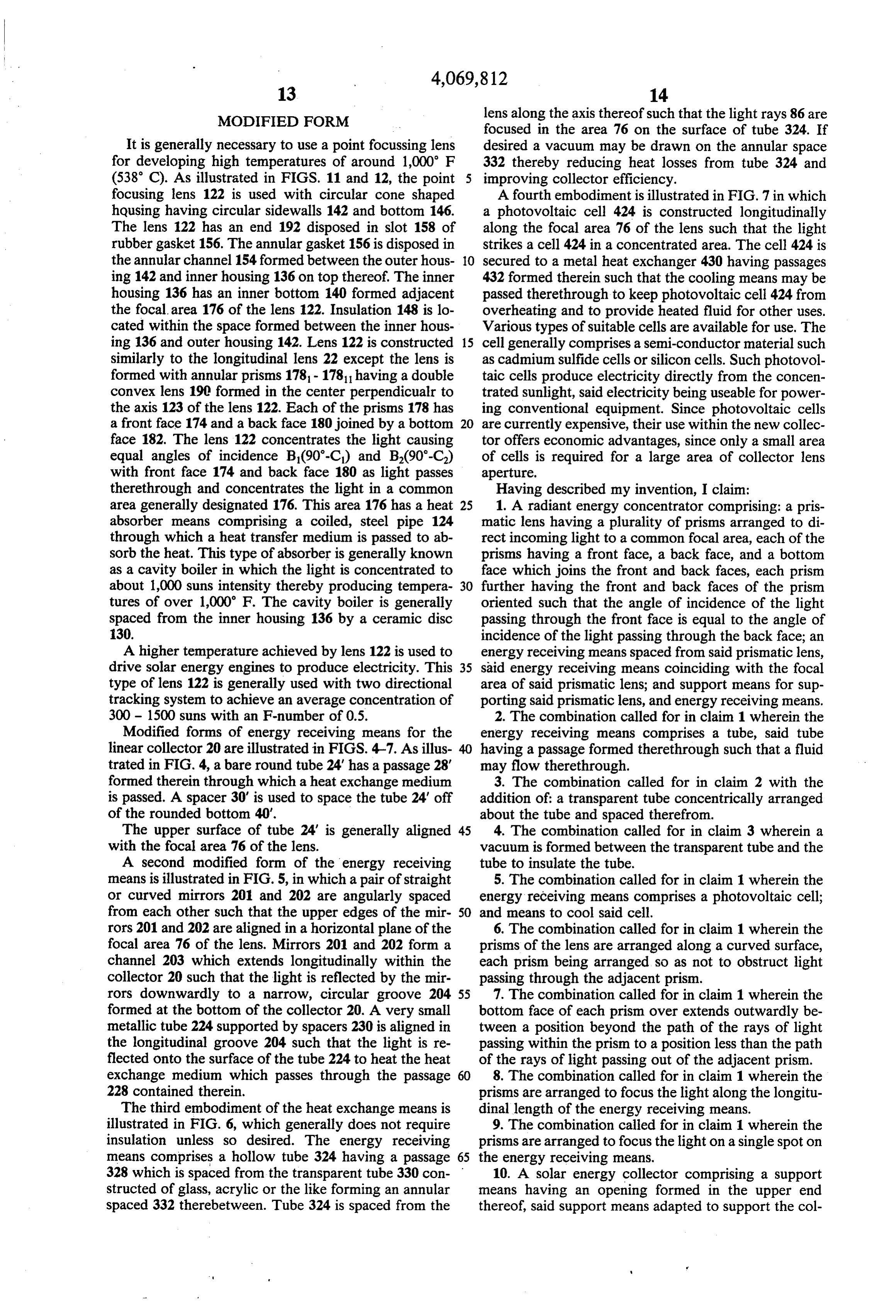
therethrough and concentrates the light in a common Having described my invention, I claim: area generally designated 176. This area 176 has a heat 25 1. A radiant energy concentrator comprising: a pris absorber means comprising a coiled, steel pipe 124 matic lens having a plurality of prisms arranged to di through which a heat transfer medium is passed to ab rect incoming light to a common focal area, each of the sorb the heat. This type of absorber is generally known prisms having a front face, a back face, and a bottom as a cavity boiler in which the light is concentrated to face which joins the front and back faces, each prism about 1,000 suns intensity thereby producing tempera 30 further having the front and back faces of the prism tures of over 1,000 F. The cavity boiler is generally oriented such that the angle of incidence of the light spaced from the inner housing 136 by a ceramic disc passing through the front face is equal to the angle of 30. incidence of the light passing through the back face; an A higher temperature achieved by lens 122 is used to energy receiving means spaced from said prismatic lens, drive solar energy engines to produce electricity. This 35 said energy receiving means coinciding with the focal type of lens 122 is generally used with two directional area of said prismatic lens; and support means for sup tracking system to achieve an average concentration of porting said prismatic lens, and energy receiving means. 300 - 1500 suns with an F-number of 0.5. 2. The combination called for in claim 1 wherein the Modified forms of energy receiving means for the energy receiving means comprises a tube, said tube linear collector 20 are illustrated in FIGS. 4-7. As illus 40 having a passage formed therethrough such that a fluid trated in FIG. 4, a bare round tube 24' has a passage 28' may flow therethrough.
formed therein through which a heat exchange medium 3. The combination called for in claim 2 with the is passed. A spacer 30' is used to space the tube 24' off addition of: a transparent tube concentrically arranged of the rounded bottom 40'. about the tube and spaced therefrom. The upper surface of tube 24' is generally aligned 45 4. The combination called for in claim 3 wherein a with the focal area 76 of the lens. vacuum is formed between the transparent tube and the A second modified form of the energy receiving tube to insulate the tube.
means is illustrated in FIG. 5, in which a pair of straight 5. The combination called for in claim 1 wherein the or curved mirrors 201 and 202 are angularly spaced energy receiving means comprises a photovoltaic cell; from each other such that the upper edges of the mir 50 and means to cool said cell.
rors 201 and 202 are aligned in a horizontal plane of the 6. The combination called for in claim 1 wherein the focal area 76 of the lens. Mirrors 201 and 202 form a prisms of the lens are arranged along a curved surface, channel 203 which extends longitudinally within the each prism being arranged so as not to obstruct light collector 20 such that the light is reflected by the mir passing through the adjacent prism. rors downwardly to a narrow, circular groove 204 55 7. The combination called for in claim 1 wherein the formed at the bottom of the collector 20. A very small bottom face of each prism over extends outwardly be metallic tube 224 supported by spacers 230 is aligned in tween a position beyond the path of the rays of light the longitudinal groove 204 such that the light is re passing within the prism to a position less than the path flected onto the surface of the tube 224 to heat the heat of the rays of light passing out of the adjacent prism. exchange medium which passes through the passage 60 8. The combination called for in claim 1 wherein the 228 contained therein. prisms are arranged to focus the light along the longitu The third embodiment of the heat exchange means is dinal length of the energy receiving means. illustrated in FIG. 6, which generally does not require 9. The combination called for in claim 1 wherein the insulation unless so desired. The energy receiving prisms are arranged to focus the light on a single spot on means comprises a hollow tube 324 having a passage 65 the energy receiving means.
328 which is spaced from the transparent tube 330 con 10. A solar energy collector comprising a support structed of glass, acrylic or the like forming an annular means having an opening formed in the upper end spaced 332 therebetween. Tube 324 is spaced from the thereof, said support means adapted to support the col
Page 14
lector; an energy receiving means positioned in the comprising a line disposed parallel to the longitudinal lower portion of the interior of said support means; a axis of the lens.
curved prismatic lens spaced from said energy receiving 22. The combination called for in claim 15 wherein means, said lens being secured to the upper end of said the prisms are arranged to direct light to a common area support means, said lens comprising a plurality of 5 comprising a concentrated spot.
prisms arranged to direct light to a common focal area, 23. The combination called for in claim 15 wherein each prism having a front face which forms the outer the focal length of the lens is less than the width of the surface of the lens, a back face and a bottom face which lens such that the F-number of the lens is less than 1.0. form the interior surface of the lens, the improvement 24. A curved Fresnel prismatic lens comprising: a comprising: the front and back faces of each prism being 10 plurality of prisms arranged along a curved surface to oriented such that the angle of incidence of the light direct incoming light to a common focal point, each of passing through the front face is equal to the angle of the prisms having a front face, a back face, and a bottom incidence of light passing through the back face. face which joins the front and back faces, each prism 11. The combination called for in claim 10 wherein further having the front and back faces oriented such the prisms of the lens are arranged along a curved sur 15 that the angle of incidence of the light passing through face, each prism being arranged so as not to obstruct the front face is equal to the angle of incidence of the light passing through the adjacent prism. light passing through the back face, and wherein the 12. The combination called for in claim 10 wherein bottom face of each prism extends outwardly from a the bottom face of each prism extends outwardly be position beyond the path of the rays of light passing tween a position beyond the path of rays of light passing 20 within the prism to a position less than the path of the within the prism to a position less than the path of the rays of light passing out of the adjacent prism so as not rays of light passing out of the adjacent prism. to obstruct any light passing through the prisms. 13. The combination called for in claim 10 wherein 25. The combination called for in claim 24 wherein the support means and lens are linear and adapted to the bottom face of the prism is oriented such that the focus light along a longitudinal area parallel to the lon 25 angle between the lens optical axis and the bottom face gitudinal axis of the lens. of the prism is greater than one-half the turning angle of 14. The combination called for in claim 10 wherein the light passing through the prism but less than the the lens is spherical and the support means is rounded to turning angle of the light. 26. The combination called for in claim 2 wherein the focus light in a common spot on the energy receiving
CaS. 30 prisms are arranged to direct light to a common area 15. A Fresnel prismatic lens comprising: a plurality of comprising a line parallel to the longitudinal axis of the prisms arranged to direct light to a common area, each lens.
of the prisms having a front face, a back face, and a 27. The combination called for in claim 16 wherein bottom face which joins the front and back faces, each the prisms are arranged to direct light to a common area prism further having the front and back faces of the 35 comprising a concentrated spot.
prism oriented such that the angle of incidence of the 28. The combination called for in claim 17 wherein light passing through the front face is equal to the angle the prisms are arranged to focus along a line. of incidence of the light passing through the back face. 29. The combination called for in claim 17 wherein 16. The combination called for in claim 15 wherein the prisms are arranged to focus on a spot. the prisms are arranged along a curved surface, each 30. The combination called for in claim 15 wherein prism being arranged so as not to obstruct light passing the lens is linear.
through the adjacent prism. 31. The combination called for in claim 15 wherein 17. The combination called for in claim 15 wherein the lens is spherical.
the bottom face of each prism over extends outwardly 32. The combination called for in claim 15 with the between a position beyond the path of the rays of light 45 addition of: a support means; and energy receiving passing within the prism to a position less than the path means spaced from said lens by said support means such of the rays of light passing out of the adjacent prism. that the light passing through the lens is focused on the 18. The combination called for in claim 16 wherein energy receiving means.
the bottom face of each prism over extends outwardly 33. A method of concentrating energy from light rays between the position beyond the path of the rays of 50 emitted from a source of energy comprising the steps of: light passing within the prism to a position less than the providing a plurality of prisms having a front and back path of the rays of the light passing out of the adjacent face joined by a bottom face; refracting the light prism. through the front and back faces of the prisms to a 19. The combination called for in claim 18 wherein common focal area such that the angles of incidence the bottom face of the prism is oriented such that the 55 with the rays refracted through the prisms is equal with angle between the lens optical axis and the bottom face respect to the front and back faces of the prism. 34. The method called for in claim 33 with the addi of the prism is an angle at least greater than one-half the turning angle of the light passing through the prism but tional steps of: arranging the prisms along the curved less than the full turning angle of the light passing there surface such that each prism does not obstruct light through. 60 passing through the adjacent prism. 20. The combination called for in claim 15 with the 35. The combination called for in claim 33 with the addition of: a support means adapted to support said additional steps of over-extending the bottom face of prismatic lens; and an energy receiving means posi each prism beyond the path of the rays passing there tioned by said support means and coinciding with the within.
focal point of the prismatic lens such that sunlight is 65 36. The combination called for in claim 1 with the concentrated on the energy receiving means. addition of means pivotally securing said support 21. The combination called for in claim 15 wherein means such that the longitudinal axis of said support the prisms are arranged to direct light to a common area means is aligned with a polar axis; means to move said
Page 15
support means for diurnal tracking of the sun; means to position of said one prism within the said prismatic move the energy receiving means relative to the lens lens means.
and align said energy receiving means at the sharpest 38. The energy concentrator as set forth in claim 37 focus of the lens as the sun changes angles of declination wherein said prismatic lens means is symmetrical rela relative to the lens. tive to a central plane passing through the receiving 37. A radiant energy concentrator comprising: axis, said radial distance being a function of the angle energy receiving means disposed along a receiving the the central plane makes with a plane passing through receiving axis and said one of said prisms.
axis;
a prismatic lens means comprised of a plurality of 1 O wherein said radialconcentrator
distance to any one of said prisms juxtaposed prisms arranged to form a generally decreases as the distance curvilinear outer surface to direct incoming light to central plane increases. from said one prism to the said energy receiving means; and 40. The energy concentrator as set forth in claim 39 means for supporting said prismatic lens means rela wherein said prism includes a front face, a back face, tive to said energy receiving means such that said 15 and a bottom face joining the front and back faces, each prismatic lens means is disposed from and curved prism being formed such that a light ray impinging upon about said energy receiving means, said prismatic said front face at a given incidence angle will pass lens means being formed in such a manner that the through said prism and emerge at substantially the same radial distance from the receiving axis to any one of given angle relative to saidisback face. said prisms varies in accordance with the relative 20
Provenance
- Collection
- Cited prior art
- Original PDF
- patentimages.storage.googleapis.com →
- Filed
- 1976-12-20
- Pages
- 15
- Method
- pdftotext (the PDF's own text layer) + pdftoppm 300dpi page scans
- Source
- Google Patents bibliographic record
- Granted
- 1978-01-24
- Inventors
- Mark J. O'Neill; E Systems Inc
- Transcribed from
- patentimages.storage.googleapis.com →