patent · US2277311
Sun water heater
24 March 1942
Page 1
Drawing sheet — no readable text.
Page 2
Drawing sheet — no readable text.
Page 3
Patented Mar. 24, 1942 2,277,311
UNITED STATES PATENT OFFICE
SUN WATER HEATER,
Charles M. Freeman, Manatee, Fla., assignor of one-half to D. B. Whittle, Palmetto, Fla.
Application May 24, 1940, serial No. 337,063
The present invention relates to improvements Strata of the hot and cold water Will be kept sep in Sun Water heaters, and more particularly re arated throughout the entire length of a long lates to a domestic or other hot water storage tank to thereby avoid any rapid dissipation of System in which the heat rays of the sun are the heat.
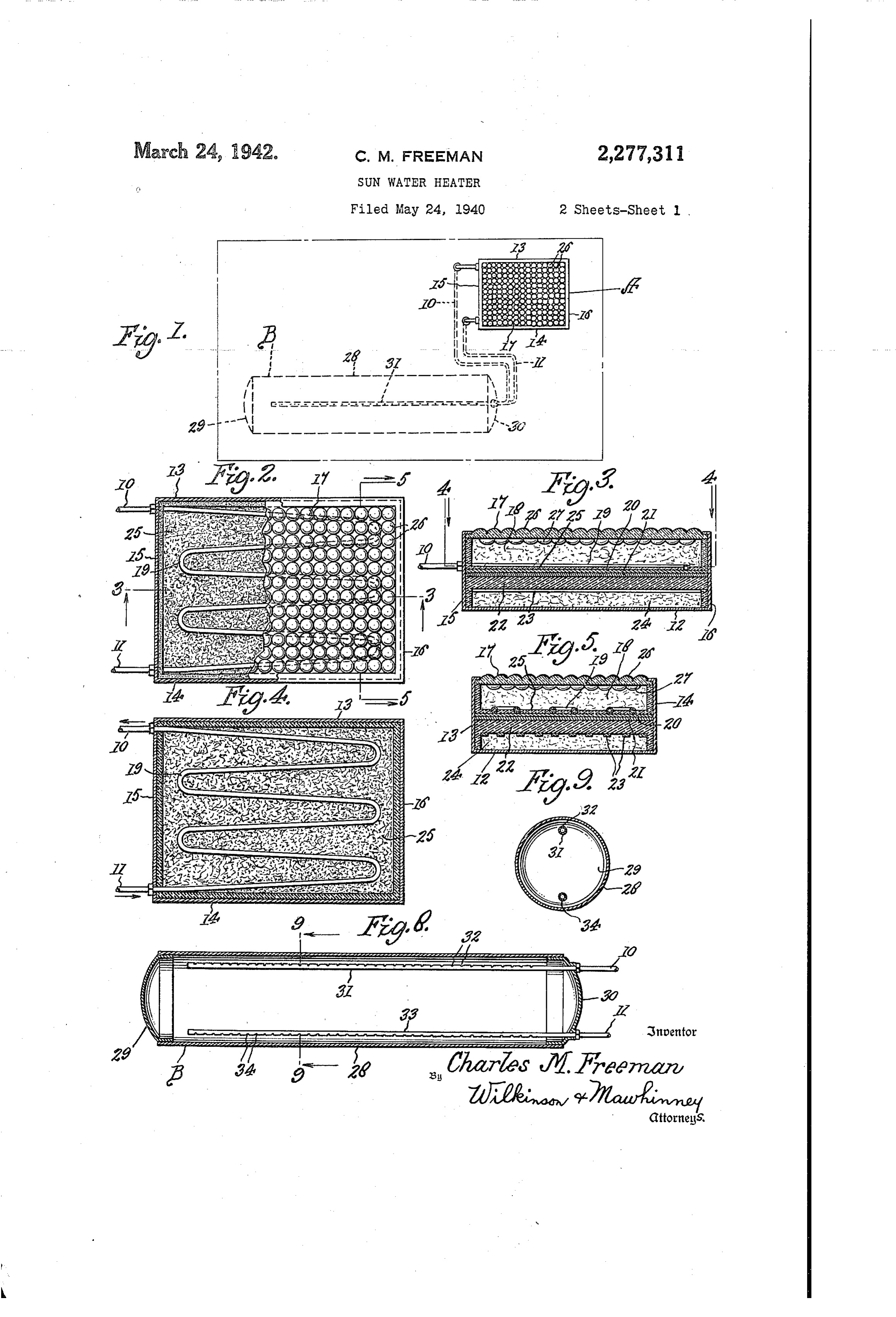
utilized in a novel form of heater to raise the With the foregoing and other objects in view emperature of the water to that high degree nec the invention will be described more particularly eSSary for use in a System of this character. hereinafter and will be more particularly point A primary object of the invention is to utilize ed out in the subjoined claims. a lens construction which Will pick up the Sun's In the drawings, in which like parts are de 5'ayS from Various angles and concentrate and () noted by similar reference characters throughout intensify the heat effect of the sun's rays by di the Several views:
recting Such rays upon a confined area for appli Figure 1 is a diagrainmatic view showing an cation to the Water undergoing heat treatment to in proved heater and connected water system the end that the natural heat energy of the sun constructed in accordance with the present in as applied to the heater will be multiplied by 5 Vention.
Concentration of rays in a manner to establish Figure 2 is a top plan view, on an enlarged high efficiency in the heater with comparatively Scale, Of the improved heater unit with parts Snail eXposure area and comparatively Small Wa broken a Way and parts shown in section. ter capacity in the heater per se to nevertheless Figure 3 is a vertical longitudinal section taken supply relatively large quantities of Water to a on the line 3-3 in Figure 2. relatively large storage tank Whereby hot Water Figure 4 is a horizontal Section taken on the in ample quantities will always be available for line 4-4 in Figure 3.
any household or other uses. Figure 5 is a vertical transverse section taken Another obect of the invention is to provide on the line 5-5 in Figure 2.
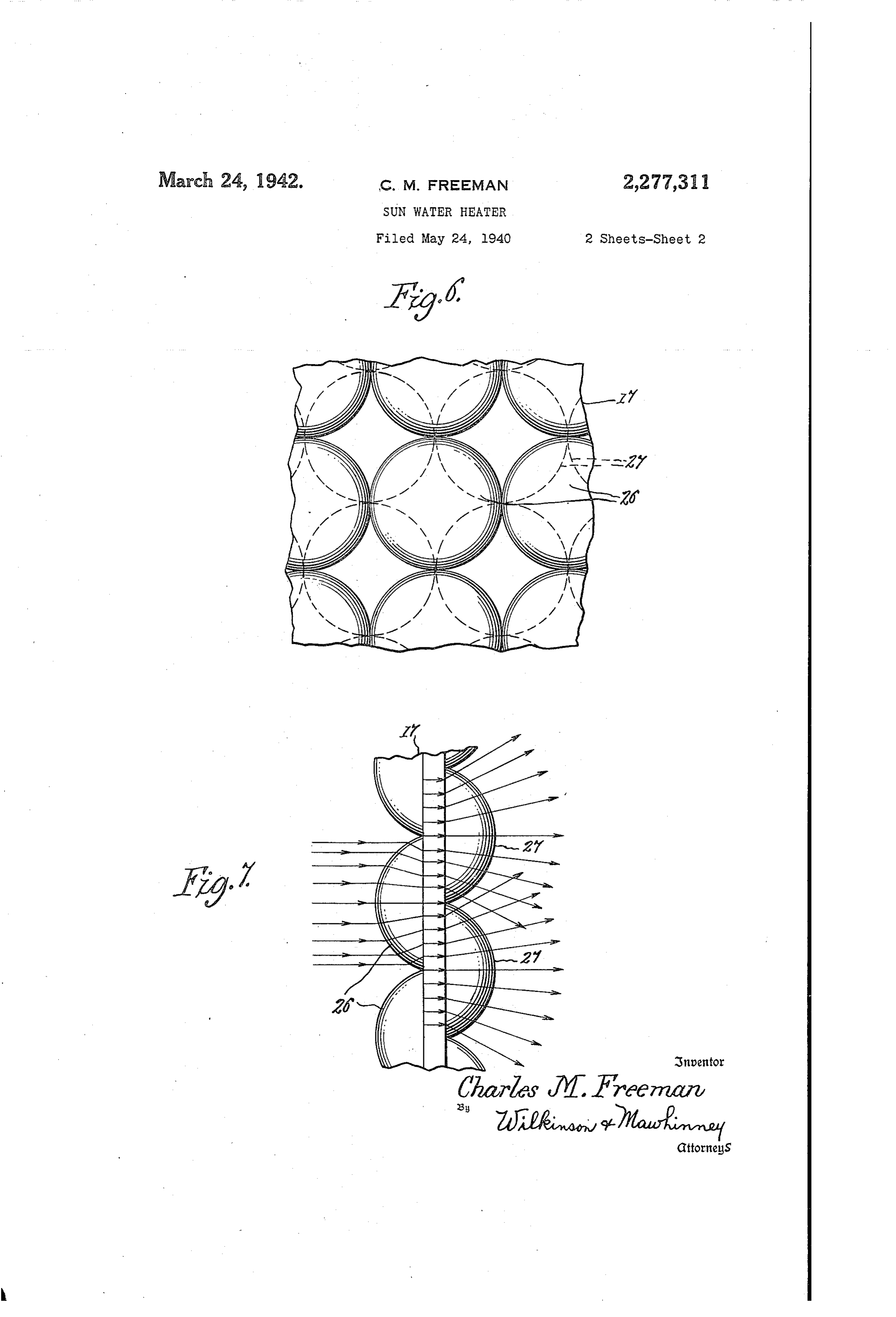
an improved form of eins in conbination. With a Figule 6 is a fragmentary plan view of the type of Water containing coil in which the in in proved lens employed.
coming Sun's rays are initially condensed to con Figure 7 is a schematic view of the lens with centrate the heat energy and thereafter Suitably the bulls separated and indicating the condens diffused into a large number of foci directed ing and diffusing effect upon the heat rays. upon the convolutions of the water containing 34) Figure 8 is a longitudinal section taken through coils and also upon the heat-reflecting Walls of an impi'oved Water storage tank employed, and the coil chamber, and if desirable upon certain Figure 9 is a cross section taken on the line heat absorbent material disposed in the chamber 3-9 in Figure 8.
in and about the coil convolutions, Such mate Referring more particularly to the drawings. A rial being for the purpose of absorbing quanti represents the improved heating unit and B a ties of the heat during daylight hours, and act Water Storage tank, the two elements being con ing in turn to yield up and give off this heat dur nected together by the pipes iO and of which ing the night or during periods of cloudy weather () is the hot water pipe circulating the hot When the Sun is obscured. Water from the heater A to the storage tank B, The invention also has for a further purpose and is the cold Water pipe which circulates an improved construction of heater unit resulting the cold Water from the lower part of the Stor in a high insulating value to retain the residual age tank B to the intake side of the heater A. heat in the heating chamber and in the water Referring more particularly to Figures 2 to 7 and in the heat absorbent material and in the 45 inclusive the improved heater unit comprises conductive reflecting walls of the Water heating generally a container made up of a bottom 2, chamber to avoid generally the dissipation of sides 3 and 4 and end walls 5 and 6. All such heat and the consequent ineficiency of the of such walls may be insulated in any approved heater; and in other words to proinote the effi ale.
ciency of the heater and to retain its absorbed The top of the container receives in its upper heat. part a lens it which is mounted therein in any A still further object of the invention is to appropriate manner. Such lens 7 encloses the provide an improved storage tank in which the heating chamber 3 in which is disposed the supply of hot water and the drawing off of the water coil 9 composed of an appropriate nun coid water is accomplished in a novel manner and by a novel pipe arrangement whereby the i55 ber of convolutions. The Water coil at one end
Page 4
connects with the hot water pipe 0 and at plate or sheet 29 and heat absorbent material 25 the other end with the cold Water pipe i. thereon.
The coil 9 is supported upon a plate or sheet Consequently heat, the effect of which is great 20 of some heat retaining material preferably ly intensified over that of the natural Sun's rays having good conductivity such as copper. Be at the point of interception, is directed upon the low the plate 20 is a metallic insulation 2 com water within the coil 9 and upon the absorbent posed preferably of aluminium alloy. Beneath material 25 so that a high degree of heat will be this sheet of aluminium alloy is a body 22 of conveyed to the water in coil 9 during periods non-metallic insulation such as rock Wool, cork, Of Sunshine Which heat is Substantially radiant Celotex or the like. This body 22 is supported O heat from the Sun. Moreover through the con upon metal strips or metal lathing 23. BelOW ductivity of the metal walls of the coil 9 the the insulation 22 is an air space 24 which may plate 20 will receive a high degree of heat which communicate With such insulation 22 through it Will conduct back to the coil 9 and the Water the strips or laths 23. therein. Moreover the heat absorbent material In the heating chamber 8 between the con 5 25 Will absorb a great amount of this heat during volutions of the coil 9 is preferably placed suit periods of Sunshine, which heat will be given off able heat absorbent maerial, such for instance durig obscuration periods of the Sun. The high as catlinite or soapstone. This material 25 ex degree of heat referred to is a high degree rela tends up from the plate 2 about half the height tively to external atmospheric temperature. This of the coil 9. So as to leave large Surface area.S 20 atmospheric temperature naturally varies widely of the convolutions of the coil 9 exposed to for Various points on the earth relatively to the the heat rays. chainging position of the sun at various seasons The lens is constructed of glass or other Of the year. Therefore the atmospheric ten translucent material and is made with upper perature and the radiant heat rays from the Sun bulbs 26 and lower bulbs 2. The upper bulbs 25 Will differ widely dependent upon location and are convex on the upper faces to intercept di time both of the day and of the season. The im rectly the rays of the sun no matter what the proved device greatly intensifies and magnifies inclination or the declination of that body may the effect of the normal radiant heat of the Sun's be. The bulbs 26 are in effect condensing lenses. rays. Actual tests made in September 1940 in They are numerous and of relatively small diam 30 Manatee, Florida, under an outside temperature eter. They act to collect and concentrate and of 85 F. showed an increase in water tempera to intensify the heat effect from the sun's rays ture up to 201° E.
and to direct the same across the intermediate The construction of the insulation Will hold flat portion of the glass lens plate 7 to the this heat in the heat absorbent material 25 over inner bulbs 27. These latter bulbs 27 are convex 35 long periods of time. The coil 9 preferably upon their lower faces and are diffusing lenses. Slopes slightly from one end to the higher end They are also numerous and may be of the same is which may be accomplished by inclining the diameter as the upper bulbs but they are offset plate 2 very slightly in the container. relatively to the bulbs 26. In other words the The lens employed herein is somewhat similar bulbs 26 and 2 are not coaxial. Their axes are 40 to that used for light reflecting purposes in the displaced relatively to one another. Patent No. 1,649,708, granted November 15, 1927, As best shown in Figures 6 and 7 the bulbs to Elmer R. Large and Charles M. Freeman, 26 and 27 are so arranged that the bulbs 27 Referring more particularly to Figures 8 and 9 have segments thereof overlapping with the cir the Storage tank B is shown to be formed of a cles of the upper bulbs 25. In the particular 45 Substantially cylindrical wall 28 and end heads form of the invention herein illustrated as an 29 and 30. Unlike ordinary storage tanks which example, segments of four such lower bulbs 27 are upended, this tank is laid with its axis sub overlap the circle of each upper bulb 26, except Stantially horizontal so that its length is hori at the edges or marginal portions of the lens it ZOntal and it has a relatively small vertical where the continuity of the pattern is neces 50 dimension.
sarily interrupted. The hot water pipe 9 has a long extension 3 As indicated in Figure 7, the direction of the lying Substantially horizontally throughout the major length of the tank. A great number of heat rays is shown as being changed upon en tering the convex upper bulbs or lenses 26 to relatively Small perforations 32 are made in the convergent lines to thereby concentrate the 55 pipe extension 3. These perforations are pref heat energy received in the heat rays from erably in a single line. All perforations have their the sun. Due to the substantially flat chair axis Substantially vertical. The perforations acter of the intermediate portion of the plate Open upwardly toward the round roof of the the lenses 26 are plano-form interiorly as are Cylindrical tank 23 and are spaced from such roof. also the upper surfaces of the lower bulbs or 60 The cold water pipe has an extension 33 lenses 27. The concentrated and intensified lying Substantially horizontally and substantially sun's rays are intercepted and picked up by the throughout the length of the tank near the bot OWer bulbs 2 and diffused within the chamber ton thereof. A line of minute perforations 34 8, it being understood that the concentrated extends downwardly from the pipe 33 toward the heat effect from a single upper bulb 26 is dis 65 rounded bottom of the tank but spaced there tributed to four underlying lower bulbs 2 and from.
that therefore the diffusing value of four bulbs Hot Water entering by Way of pipe and its 27 is available to direct the concentrated en extension 3 issues upwardly in small streams ergy from each upper bulb 26. Also each lower from the numerous perforations 32 toward the bulb 27 receives heat energy waves or rays from 70 round roof. Thus the hot water enters quietly four of the upper bulbs 26. The net effect is to at many points throughout the long horizontal produce in the heating chamber 8 a multitude length of the tank and is diverted quietly by the of focal heat points at the foci of the lower rounded roof down in opposite directions in the bulbs 27. The convolutions of the coil 9 are 75 body of liquid in the tank. The cold Water in located at such foci as is also substantially the the same way is drawn quietly through the
Page 5
numerous perforations 34 all forming individual 2. In a Sun water heater, a heating unit com outlets into the cold water pipe f, and the cold prising a heating chamber, a water coil in said water being guided downwardly to such numerous chamber, and a lens exposed to the Sun's rays outlets 34 by the round bottom portion of the and extending over said chamber and the coil tank. Thus the liquid body in the tank is kept therein, said lens having condensing bulbs on in a relatively quiescent state without that agita the upper surface thereof for intercepting the tion which would unduly tend to admix the cold Sun's rays at all angles of inclination made by With the hot water and thus dissipate the heat the Sun in its diurnal passage, and diffusing of the tank. The arrangement also tends to bulbs on the lower surface of said lens for re maintain the stratum of hot water in the upper O ceiving and diffusing the concentrated rays re portion of the tank, this stratum being maintain ceived from the external condensing bulbs, and able in a very large body due to the horizontal Said Water coil having convolutions located to elongation of the tank. The arrangement Con receive heat rays directed thereon by the dif tributes to the efficiency of the storage tank and fusing bulbs of Said lens. avoids undue drop in temperature. 15 3. In a Sun Water heater, a heating unit com The coil 9 is preferably made with relatively prising a heating chamber, a water coil in said few convolutions. Due to the nature of the lens chamber having convolutions, a plate backing 7 few convolutions are all that is necessary to Said coil and having high heat conductive and the highest efficiency. More convolutions only heat radiating properties, a lens over the coil contribute to the complexity and expense of a 20 in the chamber, said lens comprising external heater and also cause slower circulation and Condensing bulbS eXposed to the Sun for inter therefore the storage tank is apt to be exhausted cepting the Sun's rays, and inner diffusing bulbs of hot water in a shorter Space of time than eXposed to the coil and to said plate and serv where fewer coils are used. Of course only rela ing to direct the intercepted sun's rays and dif tively few of the foci of the lower bulbs 27 im 25 fuse them upon the convolutions of said coil pinge directly upon the few convolutions of coil and to Said plate.
f 9 but due to the arrangement of the bulbs 26 4. In a Sun Water heater, a heating unit com and 27 the action is adequate, particularly when prising a heating chamber, a water coil located assisted by the heat conduction of the plate 20 in Said chamber, a lens in said chamber above and the heat given off by the heat absorbent 30 the Water coil comprising upper external con material 25 when such material is used. densing bulbs exposed to the rays of the Sun, It is obvious that various changes and modi and inner diffusing bulbs spaced from said coil, fications may be made in the details of construc the inner and outer bulbs being relatively off tion and design of the above Specifically described Set.
embodiment of this invention without departing 35 5. In a Sun Water heater, a heating unit Com from the spirit thereof, such changes and modi prising a chamber, a water coil in said chamber, fications being restricted only by the Scope of the a lens in the chamber above the coil comprising following claims, inner and Outer bulbs, said outer bulbs being What is claimed is: condensing bulbs exposed to the Sun's rays for Condensing and Concentrating the same, said 1. In a sun water heater, a heating unit com 40 inner prising a container having a bottom, Sides and bulbs being diffusing bulbs for diffusing ends, a transparent lens fitted in the top of Said the concentrated rays from said outer bulbs, said container and having upper and lower bulbs inner and outer bulbs being offset axially from thereon for intercepting, concentrating and dif 45 ity ofanother,
One
Said the marginal portions of a plural inner bulbs overlapping each of said fusing the rays from the Sun into Said container, outer bulbs.
a heat absorbing metallic plate in Said container 6. In a Sun Water heater, a heating unit com Spaced substantially above the bottom thereof prising a heating chamber, a heat conducting but Spaced below said lens and forming between plate, a Water coil disposed on said plate, heat Said lens and Said plate a heating chamber, a 50 absorbent material on the plate between the water coil in said chamber spaced below said lens, convolutions of the coil, and a lens in the cham an aluminum alloy insulation sheet directly be ber above the plate having condensing and dif loW Said plate, and non-metallic insulation below fusing portions for intercepting and concen Said aluminum alloy insulation, the bottom of trating the Sun's rays and diffusing said rays Said container and said body of non-metallic 55 upon the Coil and the interposed absorbent insulation being Spaced apart to provide an in material.
Sulating air Space therebetween. CHARLES MI, FREEMAN.
Provenance
- Collection
- Cited prior art
- Original PDF
- patentimages.storage.googleapis.com →
- Filed
- 1940-05-24
- Pages
- 5
- Method
- pdftotext (the PDF's own text layer) + pdftoppm 300dpi page scans
- Source
- Google Patents bibliographic record
- Granted
- 1942-03-24
- Inventors
- Charles M Freeman; D B WHITTLE
- Transcribed from
- patentimages.storage.googleapis.com →