patent · US4205654
Solar energy unit
3 June 1980
Page 1 — bibliographic record
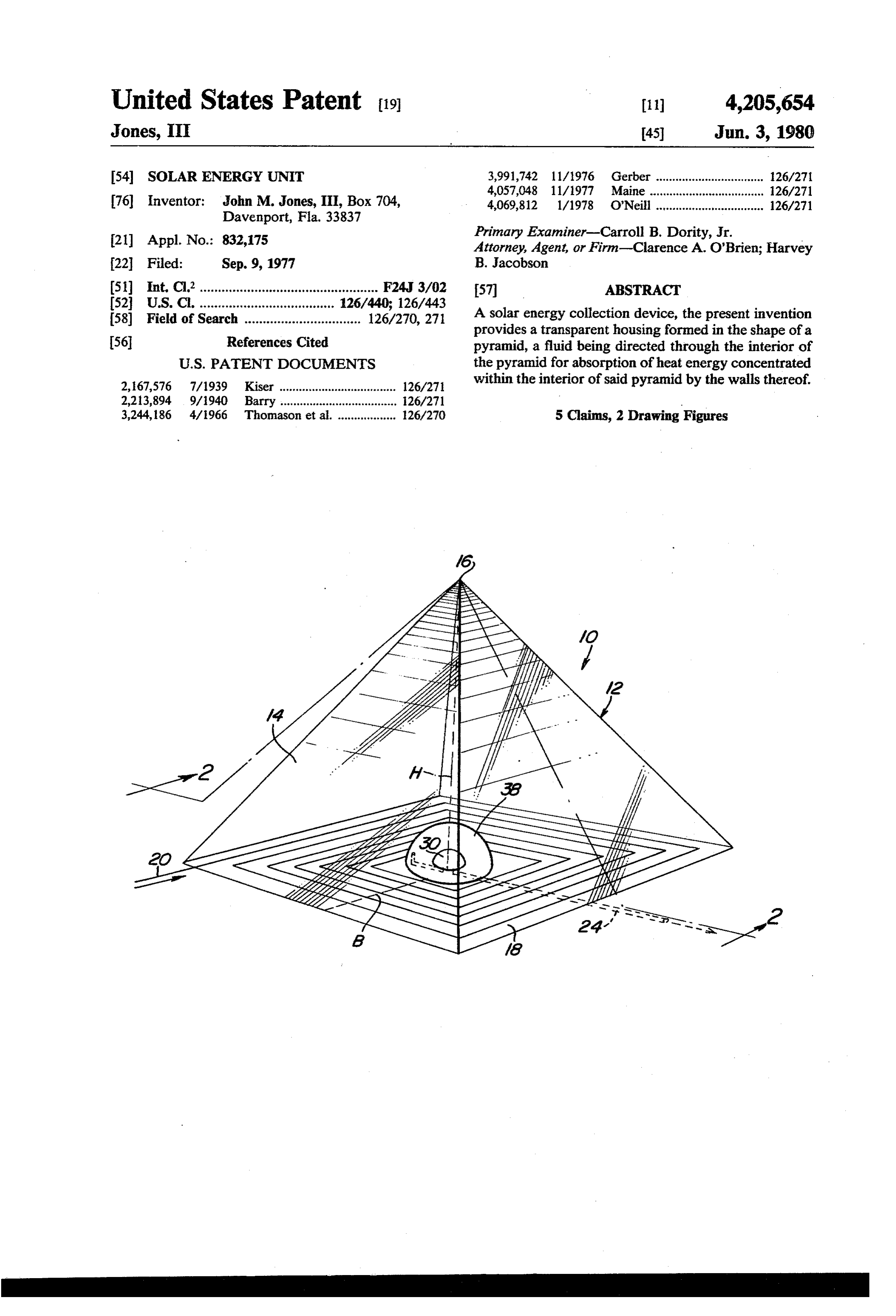
United States Patent (19) 11) 4,205,654 Jones, III 45) Jun. 3, 1980 54). SOLAR ENERGY UNIT 3,991,742 11/1976 Gerber ................................. 126/271 4,057,048 11/1977 Maine ...... ... 126/271 76 Inventor: John M. Jones, III, Box 704, 4,069,812 1/1978 O'Neill ................................. 126/271 Davenport, Fla. 33837 21 Appl. No.: 832,175 Primary Examiner-Carroll B. Dority, Jr. Attorney, Agent, or Firm-Clarence A. O'Brien; Harvey 22 Filed: Sep. 9, 1977 B. Jacobson 51) int. C.’................................................. F24J 3/02 (57 ABSTRACT 52 U.S. C. ..................................... 126/440; 126/443 A solar energy collection device, the present invention 58) Field of Search ................................ 126/270, 271 provides a transparent housing formed in the shape of a 56 References Cited pyramid, a fluid being directed through the interior of
2, 67,576 7/1939 Kiser .................................... 126/271 within the interior of said pyramid by the walls thereof. 2,213,894 9/1940 Barry .................................... 26/271 3,244,186 4/1966 Thomason et al. .................. 126/270 5 Claims, 2 Drawing Figures
Page 2
Drawing sheet — no readable text.
Page 3
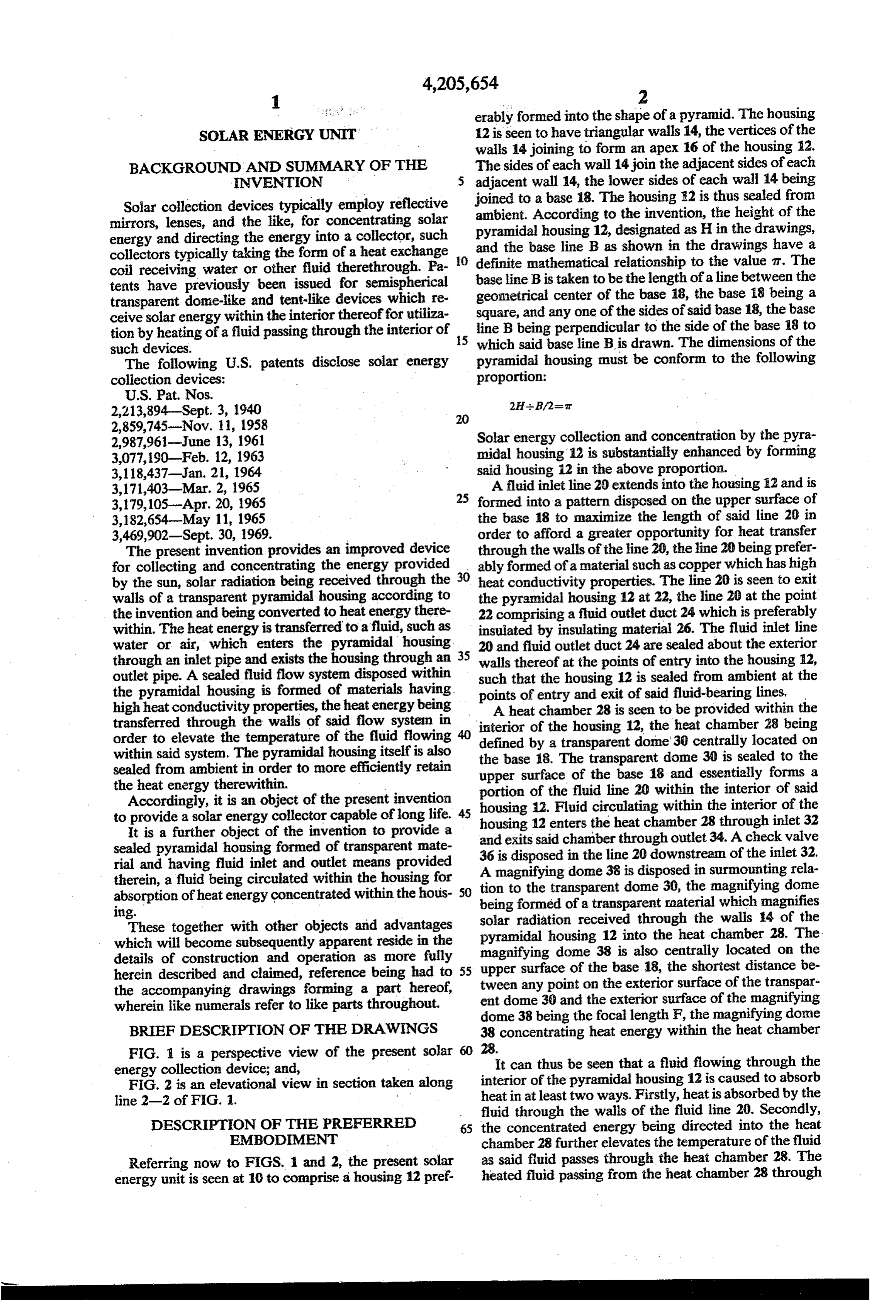
erably formed into the shape of a pyramid. The housing
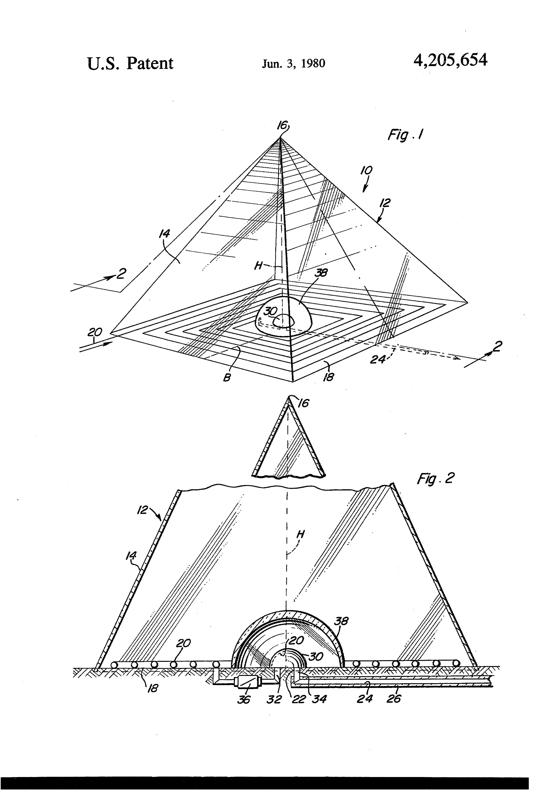
SOLAR ENERGY UNIT 12 is seen to have triangular walls 14, the vertices of the walls 14 joining to form an apex 16 of the housing 12.
BACKGROUND AND SUMMARY OF THE The sides of each wall 14 join the adjacent sides of each ENVENTION 5 adjacent wall 14, the lower sides of each wall 14 being Solar collection devices typically employ reflective ambient.to According joined a base 18. The housing 2 is thus sealed from to the invention, the height of the mirrors, lenses, and the like, for concentrating solar energy and directing the energy into a collector, such pyramidal housing 12, designated as H in the drawings, and the base line B as shown in the drawings have a collectors typically taking the form of a heat exchange 10 definite coil receiving water or other fluid therethrough. Pa base linemathematical
B is taken to relationship to the value it. The be the length of a line between the tents have previously been issued for semispherical transparent dome-like and tent-like devices which re geometrical center of the base 18, the base 18 being a ceive solar energy within the interior thereof for utiliza square, and any one of the sides of said base 18, the base tion by heating of a fluid passing through the interior of 15 line B being perpendicular to the side of the base 18 to such devices. which said base line B is drawn. The dimensions of the The following U.S. patents disclose solar energy pyramidal housing must be conform to the following collection devices: proportion:
U.S. Pat. Nos.
2,213,894-Sept. 3, 1940 2H-B/2-seat
2,859,745-Nov. 11, 1958 Solar energy collection and concentration by the pyra 2,987,961-June 13, 1961 midal housing 12 is substantially enhanced by forming
3,118,437-Jan. 21, 1964 said housing 12 in the above proportion. 3,171,403-Mar. 2, 1965 A fluid inlet line 20 extends into the housing 12 and is 25 formed into a pattern disposed on the upper surface of
3,182,654-May 11, 1965 the base 18 to maximize the length of said line 20 in 3,469,902-Sept. 30, 1969. order to afford a greater opportunity for heat transfer The present invention provides an improved device through the walls of the line 20, the line 20 being prefer for collecting and concentrating the energy provided ably formed of a material such as copper which has high by the sun, solar radiation being received through the 30 heat conductivity properties. The line 20 is seen to exit walls of a transparent pyramidal housing according to the pyramidal housing 12 at 22, the line 20 at the point the invention and being converted to heatenergy there 22 comprising a fluid outlet duct 24 which is preferably within. The heatenergy is transferred to a fluid, such as insulated by insulating material 26. The fluid inlet line water or air, which enters the pyramidal housing 35 20 and fluid outlet duct 24 are sealed about the exterior through an inlet pipe and exists the housing through an walls thereof at the points of entry into the housing 12, outlet pipe. A sealed fluid flow system disposed within such that the housing 12 is sealed from ambient at the the pyramidal housing is formed of materials having.
high heat conductivity properties, the heatenergy being points of entry and exit of said fluid-bearing lines, A heat chamber 28 is seen to be provided within the transferred through the walls of said flow system in order to elevate the temperature of the fluid flowing 40 interior of the housing 12, the heat chamber 28 being defined by a transparent dome 30 centrally located on within said system. The pyramidal housing itself is also the base 18. The transparent dome 30 is sealed to the sealed from ambient in order to more efficiently retain upper surface of the base 18 and essentially forms a the heat energy therewithin. portion of the fluid line 20 within the interior of said Accordingly, it is an object of the present invention housing 12. Fluid circulating within the interior of the to provide a solar energy collector capable of long life. 45 housing 12
It is a further object of the invention to provide a and exits saidenters the heat chamber 28 through inlet 32 sealed pyramidal housing formed of transparent mate 36 is disposed in the linethrough chamber
outlet 34. A check valve downstream of the inlet 32.
rial and having fluid inlet and outlet means provided A magnifying dome 38 is disposed in surmounting rela therein, a fluid being circulated within the housing for tion to the transparent dome 30, the magnifying done absorption of heatenergy concentrated within the hous being formed of a transparent raaterial which magnifies
These together with other objects and advantages solar radiation received through the walls 14 of the pyramidal housing 12 into the heat chamber 28. The which will become subsequently apparent reside in the details of construction and operation as more fully magnifying dome 38 is also centrally located on the herein described and claimed, reference being had to tween any pointofonthethebase 55 upper surface 18, the shortest distance be exterior surface of the transpar the accompanying drawings forming a part hereof, wherein like numerals refer to like parts throughout. ent dome 36 and the exterior surface of the magnifying dome 38 being the focal length F, the magnifying dome
BRIEF DESCRIPTION OF THE DRAWINGS 38 concentrating heat energy within the heat chamber FIG. 1 is a perspective view of the present solar 60 28.It can thus be seen that a fluid flowing through the energy collection device; and,
FIG. 2 is an elevational view in section taken along interior of the pyramidal housing 12 is caused to absorb heat in at least two ways. Firstly, heat is absorbed by the
fluid through the walls of the fluid line 20. Secondly,
DESCRIPTION OF THE PREFERRED 65 the concentrated energy being directed into the heat EMBODIMENT chamber 28 further elevates the temperature of the fluid Referring now to FIGS. 1 and 2, the present solar as said fluid passes through the heat chamber 28. The energy unit is seen at 10 to comprise a housing 12 pref. heated fluid passing from the heat chamber 28 through
Page 4
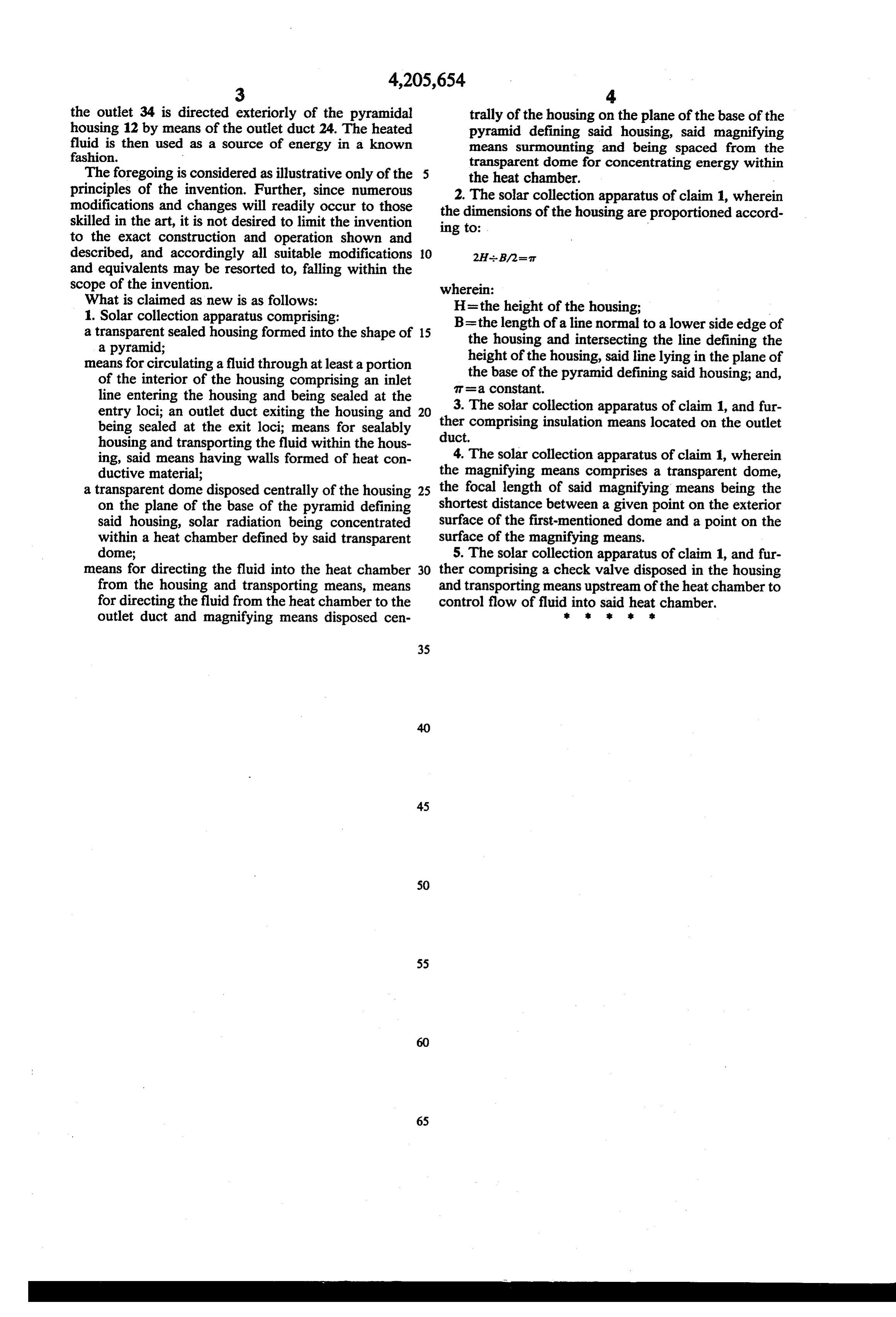
the outlet 34 is directed exteriorly of the pyramidal trally of the housing on the plane of the base of the housing 12 by means of the outlet duct 24. The heated pyramid defining said housing, said magnifying fluid is then used as a source of energy in a known means surmounting and being spaced from the fashion. transparent dome for concentrating energy within The foregoing is considered as illustrative only of the the heat chamber.
principles of the invention. Further, since numerous 2. The solar collection apparatus of claim 1, wherein modifications and changes will readily occur to those the dimensions of the housing are proportioned accord skilled in the art, it is not desired to limit the invention ing to:
to the exact construction and operation shown and described, and accordingly all suitable modifications 10 and equivalents may be resorted to, falling within the scope of the invention. wherein:
What is claimed as new is as follows: H=the height of the housing:
1. Solar collection apparatus comprising:
a transparent sealed housing formed into the shape of 15 B=the length of a line normal to a lower side edge of the housing and intersecting the line defining the a pyramid; height of the housing, said line lying in the plane of means for circulating a fluid through at least a portion the base of the pyramid defining said housing; and, of the interior of the housing comprising an inlet T=a COnStant.
line entering the housing and being sealed at the entry loci; an outlet duct exiting the housing and 20 3. The solar collection apparatus of claim 1, and fur being sealed at the exit loci; means for sealably ther comprising insulation means located on the outlet housing and transporting the fluid within the hous duct.
ing, said means having walls formed of heat con 4. The solar collection apparatus of claim 1, wherein ductive material; the magnifying means comprises a transparent dome, a transparent dome disposed centrally of the housing 25 the focal length of said magnifying means being the on the plane of the base of the pyramid defining shortest distance between a given point on the exterior said housing, solar radiation being concentrated surface of the first-mentioned dome and a point on the within a heat chamber defined by said transparent surface of the magnifying means.
dome; 5. The solar collection apparatus of claim 1, and fur means for directing the fluid into the heat chamber 30 ther comprising a check valve disposed in the housing from the housing and transporting means, means and transporting means upstream of the heat chamber to for directing the fluid from the heat chamber to the control flow of fluid into said heat chamber. outlet duct and magnifying means disposed cen sk E k
Provenance
- Collection
- Cited prior art
- Original PDF
- patentimages.storage.googleapis.com →
- Filed
- 1977-09-09
- Pages
- 4
- Method
- pdftotext (the PDF's own text layer) + pdftoppm 300dpi page scans
- Source
- Google Patents bibliographic record
- Granted
- 1980-06-03
- Inventors
- John M. Jones, III
- Transcribed from
- patentimages.storage.googleapis.com →