patent · US2872915
Solar energy apparatus
10 February 1959
Page 1
Drawing sheet — no readable text.
Page 2
Drawing sheet — no readable text.
Page 3
Drawing sheet — no readable text.
Page 4
United States Patent Office 1.
Patented Feb. 10, 1959
of apparatus is further improved by providing one or more helical vanes within the fluid circulating tube.
These vanes increase the rate and efficiency with which 2,872,915 the heat is removed from the tube by creating a cen SOLAR ENERGY APPARATUS trifugal force and turbulence in the fluid stream. As a result, a greater proportion of the fluid sweeps the
William Spencer Bowen, Westfield, N.J. inner surface of the tube to provide a more efficient heat exchange relationship.
Application February 2, 1956, Serial No. 563,099 Further, a greater improvement in the efficiency of O the fluid circulating tube is obtained by providing fins or 3 Claims. (CI. 126-271) annular rings around the tube. The fins aid in absorbing the energy received from the light rays and also add structural strength to the tube. The latter advantage allows the fabrication of a thin-walled tube, with the
This invention relates to an improved apparatus for 5 result collecting and utilizing solar energy. that the path of travel for the heat from the point Solar energy collecting devices, including parabolic the of contact of the sun's rays to the circulating fluid within tube is reduced. Structural strength is also an im mirrors, are beset by a number of critical problems which portant advantage where the circulating fluid is under have contributed to the inefficiency of prior solar energy pressure.
conversion systems. Thus, while the difficulties regard These and further advantages of the invention will be ing the collector and the concentration of the rays of more readily understood when the following description the sun at a particular point have been overcome, the is read in connection with the accompanying drawings, problems involved in retaining the collected energy as in which:
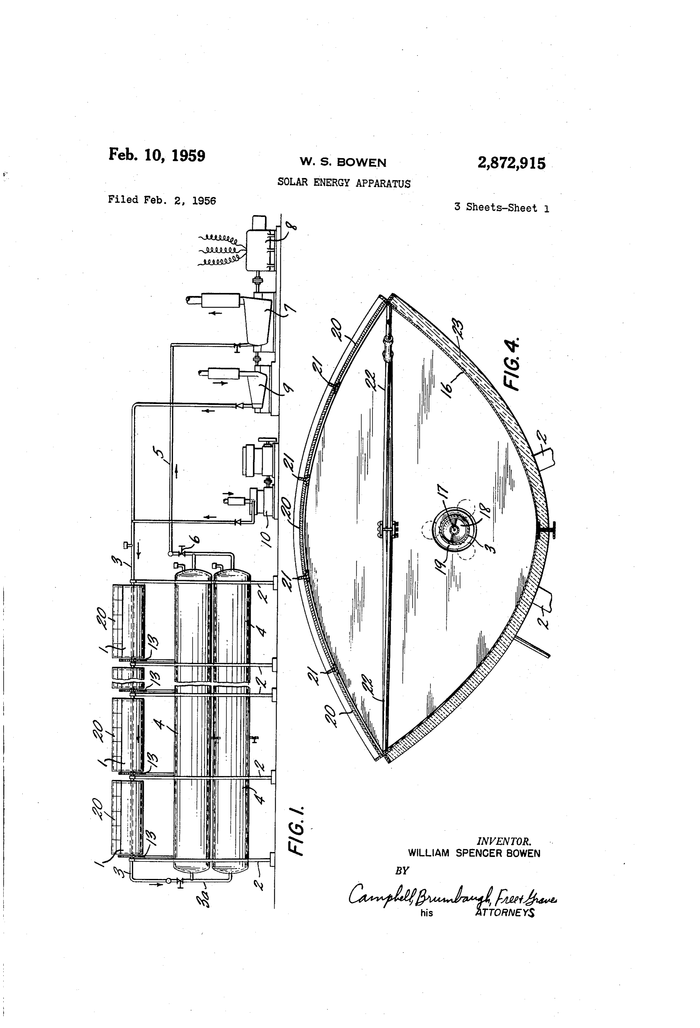
heat have become critical and have proved more difficult Figure 1 is an elevation, partially in schematic form, to solve. Attempts to prevent heat losses from these of a typical system embodying the solar energy mecha devices have included insulating the collector surfaces nism of the present invention;
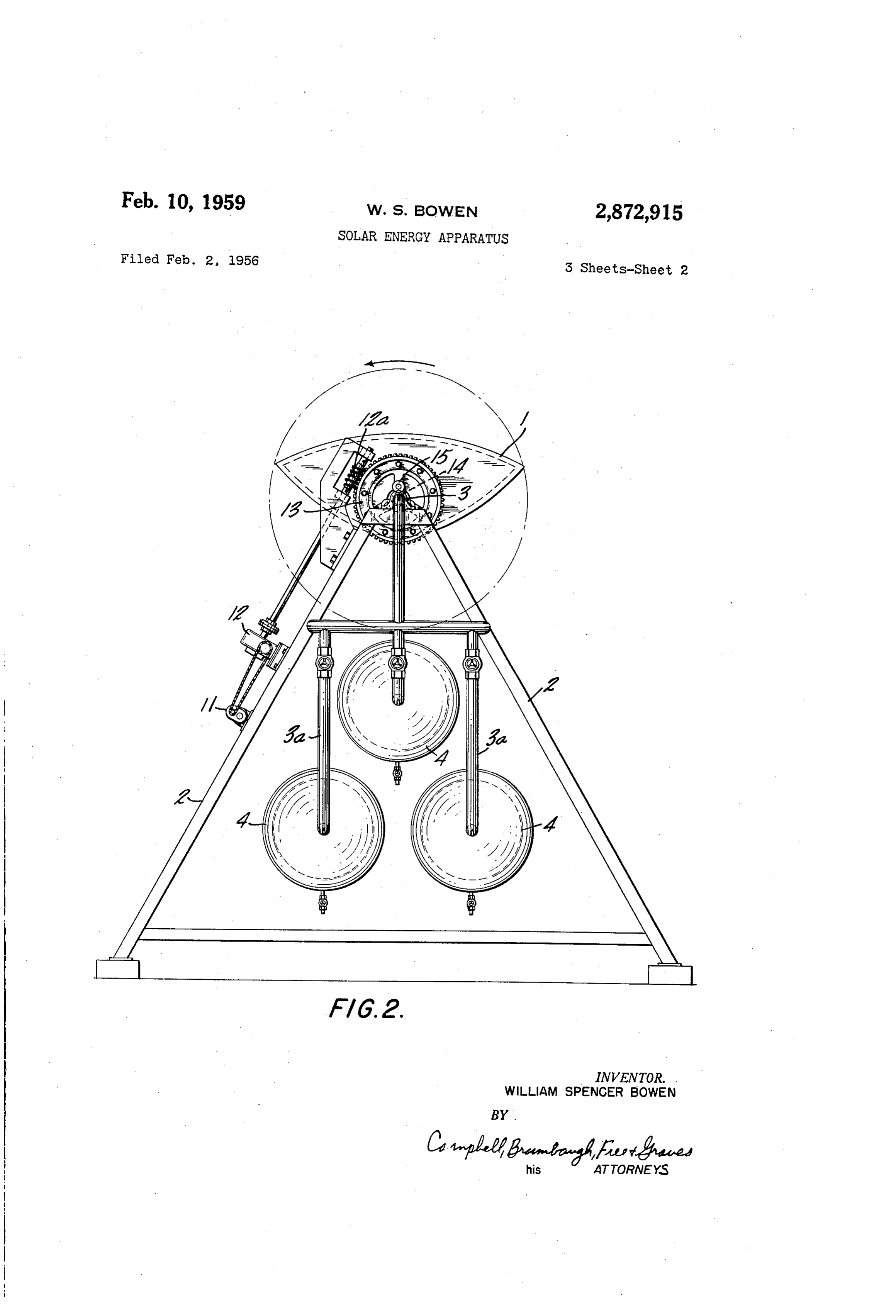
and covering its open end with a transparent material Figure 2 is an end elevation of the solar energy mech to reduce convection losses. These and other measures anism of Figure 1;
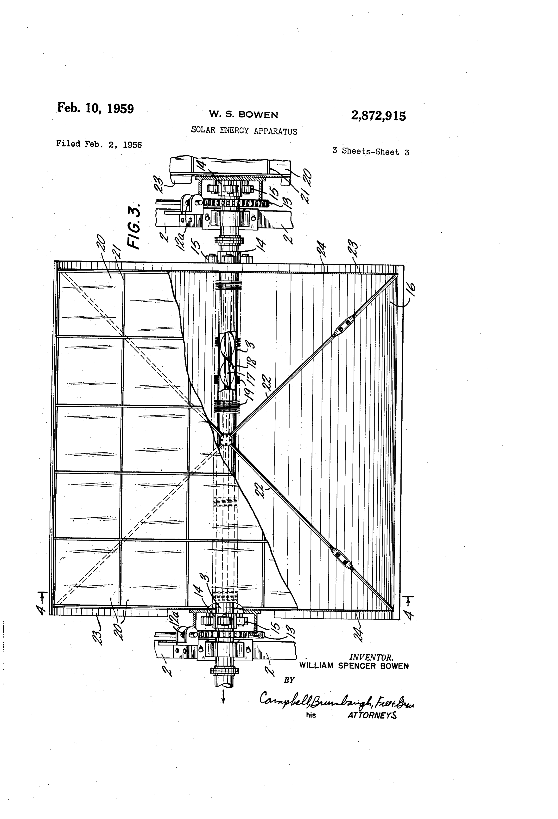
have been only partially successful, however. Figure 3 is a plan view of a solar energy collector A major cause of heat losses in parabolic mirror col 30 constructed in accordance with the present invention; and lectors resides in heat radiation from the point of con Figure 4 is a transverse section of Figure 3 taken along centration of the sun rays. In other words, since the the view line 4-4 looking in the direction of the arrows. sunlight is converted to heat at a fluid carrying tube, heat Referring to the embodiment of the invention shown waves are radiated therefron and reflected in the same in the drawings and especially to Figure 1, a series of manner as light waves. Those radiant heat waves which solar energy collectors 1, each including a pair of para return and stroke the parabolic mirror are reflected up. bolic mirrors described in detail hereinafter, are rotat ward in parallel planes and lost. Those which initially ably mounted on support frames 2. A tube 3 extends travel away from the mirror are also wasted. Where through each pair of mirrors and is positioned therein a transparent covering is placed over the mirror opening in a manner to be explained below. The tube 3 is pro to reduce convection losses, a small amount of radiant 4) vided with an extension 3a leading to storage tanks 4 heat is reflected back but not properly focused to be of mounted in any suitable manner (not shown) within the much heating volue. Therefore, most, if not all, of frames 2. Leading from the storage tanks 4 is another the radiant heat emitted from the heated tube is lost. conduit 5, controlled by a valve 6, which is connected Another problem with these devices is that of increas to a turbine 7 driving a generator 8 and a compressor 9. ing the efficiency of the heat removing means at the An auxiliary air compressor 10 may be used during the point of concentration of the sun's rays. A tube or pipe initial stages of operation of the solar energy collecting is generally provided about the principal focus of the mechanism.
parabolic mirror, a fluid being circulated through this The drive elements rotating the collectors 1 are best pipe or tube to absorb the heat and remove it from the shown in Figure 2. A motor 11 drives a speed reducer 12 apparatus. In this regard, it is important that the heat 50 coupled by a worm gear 2a to a large gear drum 13 be removed as quickly as possible so that heat losses, which is in turn fixed to the end of each of the collectors particularly those due to radiation, are minimized. 1. Of course, the collectors 1 may be appropriately Accordingly, a primary object of the present invention joined and rotated by a single driving mechanism. Each is to provide solar energy collecting and utilizing appa of the driving mechanisms is timed so that the mirrors ratus of greatly improved efficiency. 55 will make one complete revolution every twenty-four Another object of the invention is to prevent to a hours.
great extent the usual losses of heat due to radiation One of the solar energy collectors 1, shown in detail in a parabolic mirror solar energy collector. in Figures 3 and 4, is rotatably mounted on the tube 3 A further object of the invention is to provide more by means of an annular surface 14 which supports roller efficient means for removing heat from a solar energy 30 bearings 15 carried thereby. Thus, the tube 3 serves collector. as both a shaft for the rotation of the solar energy collect These and other objects of the invention are accom ing device 1 and as a fluid conduit for the passage of a plished by disposing a secondary transparent parabolic heat transfer fluid. Preferably, the tube 3 is formed of mirror as a cover over a primary reflecting mirror so a highly heat conductive metal with a black surface. that the axis of principal focus of the secondary trans However, it may be desirable to cause photo-chemical parent parabolic mirror coincides with that of the pri changes within the fluid and in this event, the tube 3 mary reflecting parabolic mirror. This arrangement in may be made of a transparent material such as "Lucite' or glass so that light waves, particularly the short wave creases the efficiency of a solar energy mechanism of the lengths, may penetrate it.
parabolic mirror type by greatly reducing radiation heat 70 The collector losses. 1 comprises a highly polished primary It has also been found that the efficiency of this type parabolic semicylindrical reflector or mirror 16 which has an axis of principal focus at line 17. The primary re
Page 5
flector 16 may be formed, for example, of highly pol wardly only a very small proportion of received solar ished copper clad steel, and serves to collect all primary energy, plane waves or parallel rays from the sun and converge The fins or annular rings 19 aid in trapping the sun them on the tube 3 which is positioned coaxially with light and in converting it into heat. Light rays falling the axis of principal focus 17. A double helical guide on the tube 3 at an angle other than 90° are reflected vane 18 positioned within the tube 3 assists is mixing the from a fin surface to an adjacent fin surface, losing fluid to provide for efficient heat, transfer. in addition, energy at each contact with a ring. The fins in turn the exterior of the tube 3 is formed with fins 19 which conduct the heat to the tube 3. As aforementioned, the greatly improve its heat absorbing properties. The con fins also provide additional structural strength to the verged rays heat the tube 3 and the fluid circulating () tube 3, which is particularly desirable where a thin tube therethrough which flows from the collector 1 through is employed and where the fluid is under pressure. the pipe section 3a into the storage tanks 4. A fluid, for example air, passing through the tube 3 To complete the solar energy collector , a secondary efficiently picks up heat energy since the vanes 18 sweep transport parabolic mirror 20 comprising a series of panes it around the tube interior. Therefore, when the air of glass, sheets of methyl methacrylate polymer such as discharges from the solar energy collector into the "Lucite,” or similar transparent material is arranged in storage tanks 4, is may be employed in operating the tur the form of a parabola having its axis of principal focus bine 7.
at line 17 supported by an appropriate frame 2. The More particularly, the operating cycle of the system sheets or panes are preferably curved to conform to the is10 initiated with the diesel motor driven air compressor delivering air at about 100 p.s. i. through tube 3.
parabola, although they may be flat, and fitted into a Once the apparatus is in operation, the valve 6 is opened. parabolic frame 21. The collector i is strengthened by bracing it with crisscrossed tie rods and turn buckles 22. to supply heated air to the turbinc 7 which, in addition Suitable insulation material 23 may be disposed on the to driving the generator 8, operates the compressor 9. primary mirror 16 and on side plates 24 to further reduce 2 5 sincethisthetime,
At the diesel compressor 0 can be shut down compressor 9 takes over its function. The heat losses.
The transparent mirror 20 may in addition be formed heated compressed air collected in the storage tanks may be used immediately to produce electricity by operating of well-known one-way light transfinission elements. the turbine-generator combination 7, 8 or, if desired, may Examples of these include half-silvered or partially
Silvered glass or transparent plastic mirrors which have 30 beThe stored for future use.
exemplary system has been described with par one surface partially covered with finely divided silver or ticular reference to the use of compressed air as the heat other suitable metallic film. These elements transmit light received from the sun but reflect a considerable absorbing and exchange fluid. Other fluids such as water amount of the light and radiant heat waves striking the are better conductors of heat and may be used where its under-surface of the mirror. supply is plentiful. However, the most favorable weather In place of metal films, more transparent materials such conditions for the operation of solar energy systems are. as zinc sulfate and titanium dioxide, when applied to generally found in arid regions and for this reason, air glass in thin, discontinuous coatings, will allow passage. must, It of necessity, be utilized in such systems.
will be understood that the above-described embodi of up to 98% of the sunlight, but will reflect on the ment of the order of 20 to 30% of light rays and radiant heat waves d) will occur toinvention is illustrative only and modifications those skilled in the art. Therefore, the from the interior surface, for example.
The transmission efficiency of the transparent mirror invention disclosed is not to be limited to the specific apparatus herein but is to be defined by the appended is further increased by reducing the reflectivity of the exterior surface of the transparent element. Consider claims. I claim:
able reduction in reflectivity is obtained, for example, by 1. In apparatus for collecting solar energy, a primary treating the outer surface with a 1% solution of acid semicylindrical sodium phosphate for eighteen hours as 80° C. Solu semicylindrical parabolic mirror, a secondary transparent parabolic partial mirror forming a closure tions of copper sulfate (2%) and phosphoric acid (1%) may also be employed according to well known proced over primary and having the same axis of principal focus as the mirror, a heat receiving tube positioned coaxially ures with similar reduction in reflectivity. with the common axis of principal focus, a portion of In a typical operation of the above described embodi ment of the invention, the principal axis i7 is disposed the heat radiated from the lower half of the heat receiving tube being reflected by the primary mirror to the sec in a north and south direction with the solar energy col ondary mirror and reflected therefrom to the heat re lectors 1 preferably being at the south end. The ro tatable Solar energy collectors 1 are then revolved from 5 5 ceiving tube, and a portion of the heat radiated from the upper half of the heat receiving tube being reflected east to west following the sun in its course. lf greater by the secondary mirror to the primary mirror and re efficiency is desired, the north end of the system may flected therefrom to the heat receiving tube. be suitably raised to place the solar energy collectors 2. In apparatus for collecting solar energy, a primary in a plane perpendicular to the sun's rays.
The parallel rays of the Sun pass through the transpar 60 relative to the parabolic
Semicylindrical mirror arranged to be concave
Sun, a secondary transparent semicylin ent secondary reflector 20 and are focused by the parabolic drical parabolic partial mirror arranged to be convex rela mirror 16 on the centrally located tube 3 which may be tive to the stan while forming a closure over and having blackened to promote absorpton of the heat energy. the same axis of principal focus as the primary mirror, Absorption of energy is also promoted by the fins 19. a heat receiving tube positioned coaxially with the com Since the tube 2 attains a high temperature, heat en mon axis of principal focus, a double helical guide vane ergy is radiated therefrom in all directions. The heat positioned within the heat receiving tube, a portion of the waves impinging on the primary reflector 16 are reflected heat radiated from the lower half of the heat receiving in parallel planes toward the secondary parabolic re tube being reflected by the primary mirror to the sec flector 20. Therefore, a substantial portion of them will ondary mirror and reflected therefrom to the heat receiv be returned to the tube 3. In addition, those radiated ing tube, and a portion of the heat radiated from the heat waves which strike the secondary reflector 20 are upper half of the heat receiving tube being reflected by the secondary mirror to the primary mirror and reflected reflected in parallel planes to the primary reflector 16 which focuses them on the tube 3. In view of the fore therefrom to the heat receiving tube. going, it will be apparent that each of the collectors 1 75 3. In apparatus for collecting solar energy, a primary acts similarly to a "black body' since it radiates out Semicylindrical parabolic mirror arranged to be concave
Page 6
relative to the sun, a secondary transparent semicylindrical 6 parabolic partial mirror arranged to be convex relative to 820,127 Pope ------------------- May 8, 1906 the sun while forming a closure over and having the same 1,024,436 Cortault --------------- Apr. 23, 1912 axis of principal focus as the primary mirror, a heat re 1,457,565 Warrick ----------------- June 5, 1923 ceiving tube positioned coaxially, with the common axis 1,683,266 Shipman ---------------- Sept. 4, 1928 of principal focus, the secondary transparent semicylin 1,707,812 Lynch ------------------ Apr. 2, 1929 drical parabolic mirror being formed of a one-way light 1,833,876 McGrath -------------- Nov. 24, 1931
transmission substance arranged to transmit a greater 1989,999 Niederle ----------------- Feb. 5, 1935 amount of light to the interior of the apparatus, a por 2,068,955 Kritzer ----------------- Jan. 26, 1937 tion of the heat radiated from the lower half of the heat O 2,156,352 Peterson ---------------- May 2, 1939 receiving tube being reflected by the primary mirror to 2,182,222 Courtis et al. ------------ Dec. 5, 1939 the secondary mirror and reflected therefrom to the heat 2,460,482 Abbot ------------------ Feb. 1, 1949 receiving tube, and a portion of the heat radiated from 2,467,885 Freund ---------------- Apr. 19, 1949 the upper half of the heat receiving tube being reflected 2,575,478 Wilson ----------------- Nov. 20, 1951 by the secondary mirror to the primary mirror and re 5 flected therefrom to the heat receiving tube.
References Cited in the file of this patent
UNITED STATES PATENTS
Provenance
- Collection
- Cited prior art
- Original PDF
- patentimages.storage.googleapis.com →
- Filed
- 1956-02-02
- Pages
- 6
- Method
- pdftotext (the PDF's own text layer) + pdftoppm 300dpi page scans
- Source
- Google Patents bibliographic record
- Granted
- 1959-02-10
- Inventors
- Bowen William Spencer
- Transcribed from
- patentimages.storage.googleapis.com →