patent · US4045246
Solar cells with concentrators
30 August 1977
Page 1 — bibliographic record
United States Patent (19) (11) 4,045,246 Mlavsky et al. (45) Aug. 30, 1977
(54) SOLAR CELLS WITH CONCENTRATORS trated Solar Energy," Solar Energy vol. 10, No. 3, pp.
75 Inventors: Abraham I. Mlavsky, Lincoln, Mass.; R. Winston, "Principles of Solar Concentrators of a Roland Winston, Chicago, Ill. Novel Design," Solar Energy, vol. 16, pp. 89-95 (1974). B. H. Beam et al. "Experiments on Solar Photovoltaic 73) Assignee: Mobil Tyco Solar Energy Power Generation Using Concentrator and Liquid Corporation, Waltham, Mass. Cooling," Proc. 11th IEEE Photovoltaic Specialists 21 Appl. No.: 603,276 Conference, Scottsdale, Ariz., May 6-8, 1975, pp.
(22 Filed: Aug. 11, 1975 Chemical & Engineering News, July 21, 1975, p. 16. Chemical & Engineering News, Aug. 5, 1974, pp.
51) Int, C. ............................................. H01, 31/04 18-20, (52) U.S. Cl. ............................... 136/89 PC; 126/270; Primary Examiner-John H. Mack 126/271 Assistant Examiner-Aaron Weisstuch 58 Field of Search ..................... 136/89, 206, 89 PC; Attorney, Agent, or Firn-Schiller & Pandiscio
(56) References Cited The invention provides a unique arrangement for cool
2,402,662 6/1946 Ohl ......................................... 136/89 collecting solar radiation and concentrating the same on 2,946,945 7/1960 Regnier et al. .......................... 320/2 the solar cells.The solar energy concentrators are each 3,229,682 l/1966 Perlmutter et al....... ... 126/270 characterized by having a chamber with a solar radia 3,490,950 1/1970 Myer ...................................... 36/89 tion transmissive entrance wall, sidewalls adapted to 3,923,381 12/1975 Winston .................., ... 350/293 concentrate solar radiation, one or more solar cells 3,957,031 5/1976 Winston ............... ... 126/270 disposed in each chamber, and means for passing a die 3,985,116 10/1976 Kapany .................... ... 126/270 lectric, transparent cooling fluid through each chamber. 3,988,166 10/1976 Beam ...................................... 136/89 The cooling fluid has an index of refraction which pro 4,002,499 A1977 Winston ............................... 136/206 motes solar energy concentration onto the solar cells in
OTHER PUBLICATIONS addition to that provided by the sidewalls. W. A. Beckmann et al., “Design Considerations for a 12 Claims, 11 Drawing Figures 50-Watt Photovoltaic Power System Using Concen
Page 2
Drawing sheet — no readable text.
Page 3
Drawing sheet — no readable text.
Page 4
Drawing sheet — no readable text.

Page 5
Drawing sheet — no readable text.
Page 6
Drawing sheet — no readable text.
Page 7
FIG. 4 is a longitudinal sectional view of one end of
SOLAR CELLS WITH CONCENTRATORS the same apparatus;
FIG. 5 is a plan view showing a number of the devices
This invention relates to apparatus for converting of FIG. 1 disposed in parallel;
solar energy to electricity and more particularly to FIG. 6 is a schematic cross-sectional view illustrating improved solar cell apparatus of the type designed to the path followed by a single ray of solar energy in the convert solar energy to electrical energy. apparatus of FIG. 1;
As is well known, solar cells capable of directly con FIG. 7 is a cross-sectional view of a battery of solar verting solar energy to electrical energy, e.g., silicon cell-concentrator assemblies constituting a modification P-N junction solar cells, tend to undergo a loss of con 10 ofFIGS.the invention; and 8-11 are cross-sectional views of additional version efficiency if subjected to heat. Solar cells tend to heat up as a result of adsorption of radiation by the modifications of the invention.
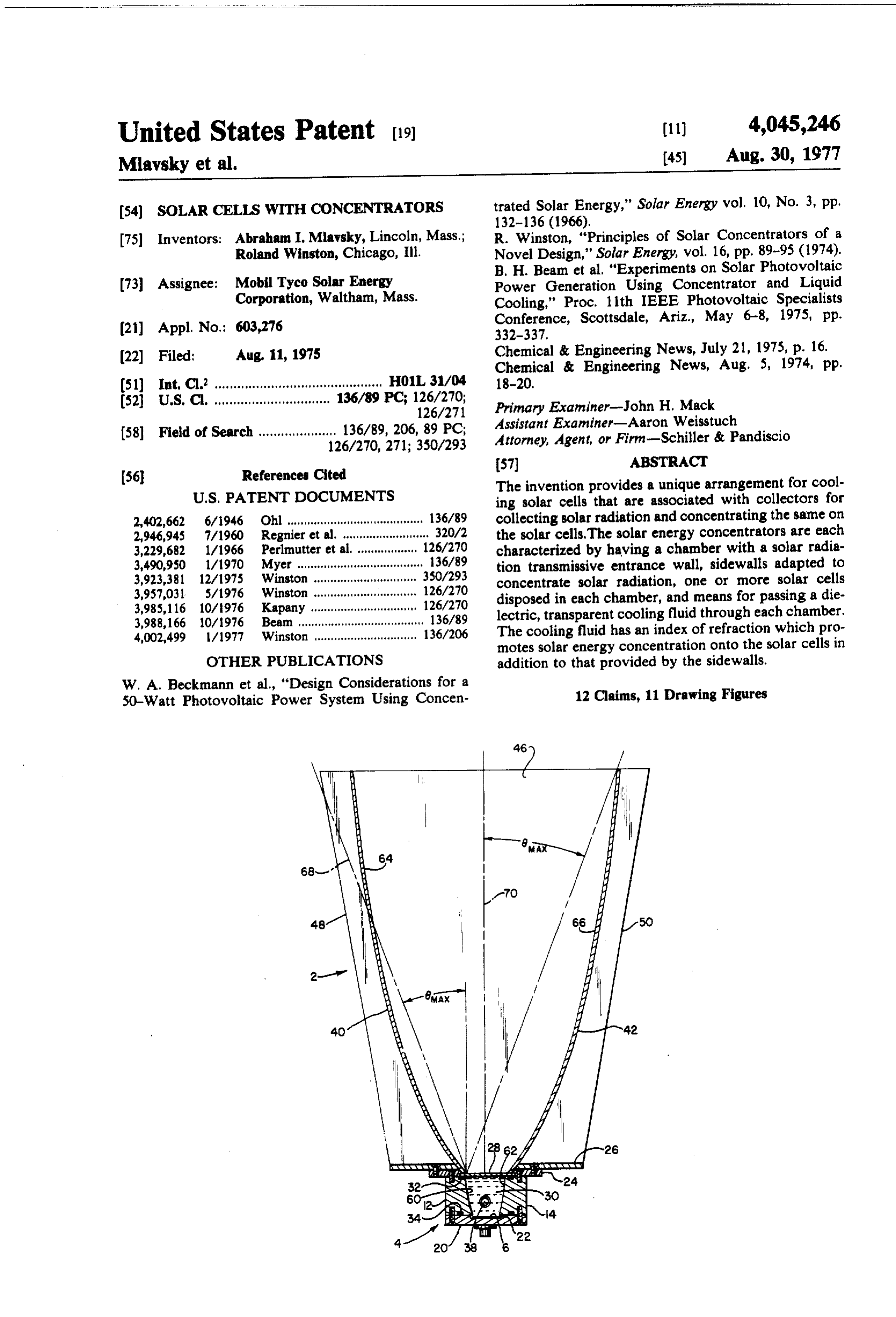
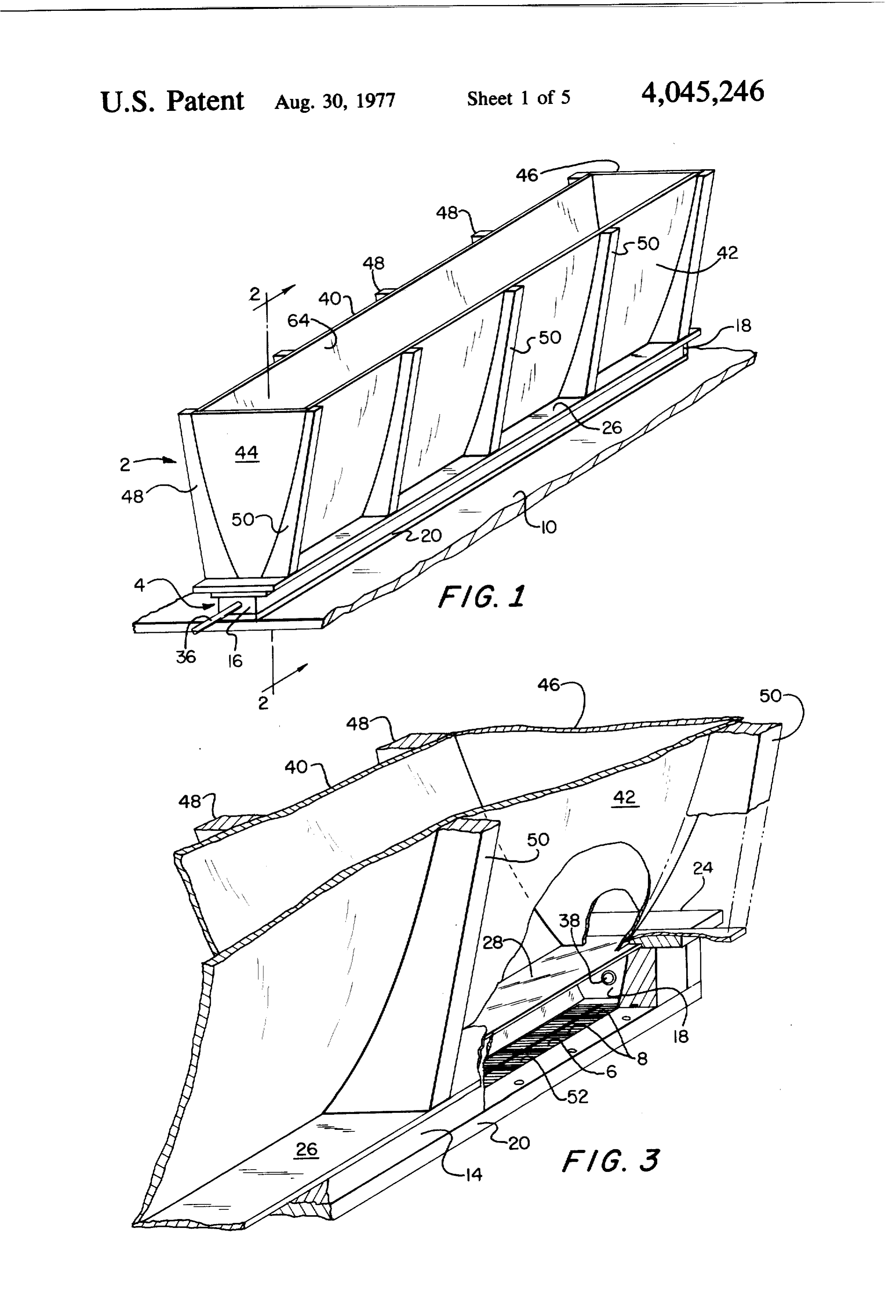
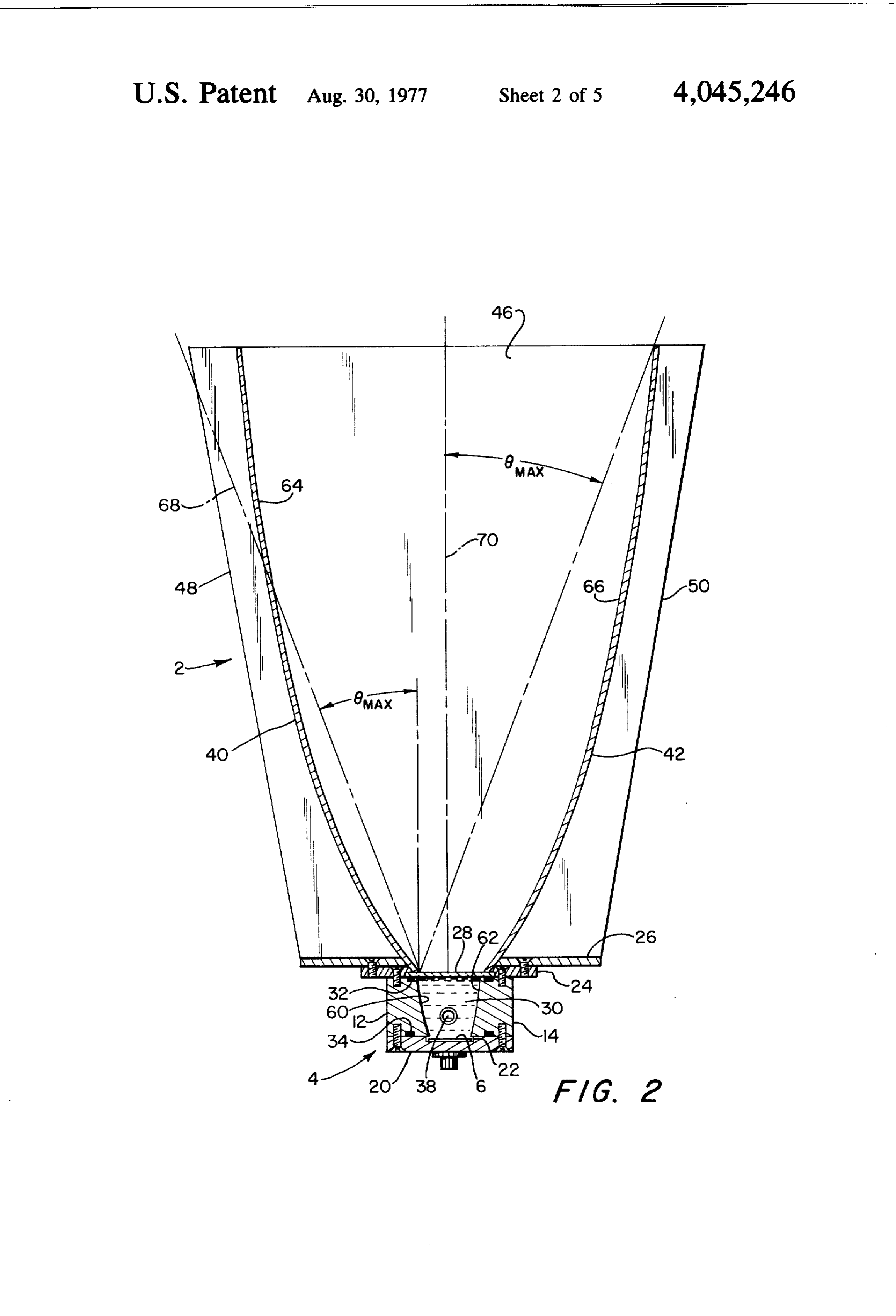
solar cells or associated structure and also due to IR In the drawings, like numerals refer to like parts. losses. Hence it is desirable to provide cooling means Referring now to FIGS. 1-4, the illustrated apparatus for maintaining the solar cells at a temperature which is 15 comprises first and second trough-like radiant energy acceptable with respect to maintaining conversion effi concentrators 2 and 4 respectively disposed one above ciency. Cooling the solar cell apparatus also helps avoid the other, and a flat solar cell panel 6 which is assumed undue stressing of mechanical components due to ther to comprise an array of solar cells 8 disposed at the exit mal expansion and contraction. This latter reason for aperture of concentrator 4. The foregoing apparatus is cooling is important since it is standard practice to elec 20 positioned on and secured to a mounting plate 10. trically interconnect a plurality of solar cells in series wall The lower concentrator 4 comprises opposite side and/or in parallel for the purpose of achieving a se members 12 and 14 and end wall members 16 and lected output voltage and/or current, Furthermore, for 18 which are secured by screws to a bottom wall mem practical solar power plants, it may be necessary or ber 20. The latter has a groove 22 extending longitudi desirable to employ light collectors for collecting solar 25 nally thereof between side wall members 12 and 14 and radiation and concentrating it on selected surfaces of mounted in the groove 22 is the flat panel 6 of solar cells the solar cell apparatus. 8. Attached by screws to the flat upper surfaces of side Therefore, the primary object of this invention is to wall members 12 and 14 and end wall members 16 and provide solar cell apparatus of the character described 18 is a flat elongate mounting plate 24. The latter has a which comprises a unique arrangement for concentrat 30 rectangular opening therein whose length is almost ing solar radiation and cooling the solar cell or cells. exactly the same as the distance between end wall mem A further object is to provide a solar cell apparatus bers 16 and 18 and whose width is slightly greater than with a radiant energy concentrator assembly which the distance between the confronting inner edge of the includes means for cooling the solar cell or cells, upper surfaces of side wall members 12 and 14. At its Still another object is to provide apparatus compris 35 inner edges which define this rectangular opening, the ing one or more solar cells, means for concentrating plate 24 is undercut to form a recess to receive the four radiant energy onto the cells, and means for disposing a edges of a rectangular glass or plastic plate 28 which is cooling fluid in a heat-exchange relation with the solar capable of passing solar radiation. The transparent plate cells, 28 is held by mounting plate 24 down against the upper A further object is to provide apparatus for convert 40 surfaces of wall members 12, 14, 16 and 18 and coacts ing solar radiation to electrical energy which comprises with the latter and bottom wall member 20 to form a a plurality of solar cells and concentrators disposed in a closed trough-like chamber capable of being filled with predetermined manner, and means forming part of the a selected cooling fluid 30. Resilient gaskets 32 and 34 concentrators for directing a cooling fluid to contact are interposed between wall members 12, 14, 16 and 18 the solar cells. 45 on the one hand and plate 28 and bottom wall member These objects and other objects and advantages here 20 on the other hand to prevent leakage of fluid 30 from inafter set forth or rendered obvious are achieved by the chamber. Although not shown, it is to be under providing an apparatus which comprises one or more stood that additional gaskets may be interposed be solar energy concentrators which are characterized by tween each of the end wall members 16 and 18 and the a chamber having a wall which is made of a material 50 confronting end surfaces of wall members 12 and 14 to capable of passing solar radiation, one or more solar further assure against leakage of fluid. However, end cells disposed in each chamber, and means for passing a wall members 16 and 18 are fitted with ports to which dielectric cooling fluid through each chamber so as to are connected conduits 36 and 38 respectively for use in effect cooling of the solar cell or cells, the cooling fluid circulating fluid through the lower concentrator. being capable of passing solar radiation and having an 55 The upper concentrator comprises two opposite side index of refraction which promotes concentration of and wall members 40 and 42, and two end wall members 44 the solar energy onto the solar cells. 46. The end wall members are secured to the side Other features and advantages of the invention are wall members and the latter are secured to and braced disclosed or rendered obvious by the following detailed by two groups of cant frame members 48 and 50 which description which is to be considered together with the 60 are attached to a mounting plate 26 that overlies and is accompanying drawings wherein: secured to plate 24. Plate 26 has a rectangular opening FIG. 1 is a perspective view of a preferred embodi that is similar to and aligned with the rectangular open ment of the invention; ing in plate 24. As is apparent, the wall members 40, 42, FIG. 2 is a cross-sectional view of the apparatus of 44 and 46 also form a trough-like chamber which is FIG. 1; 65 open at the top but closed off at the bottom by transpar FIG, 3 is an enlargement of a portion of FIG. 1 with ent plate 28.
a part of the radiant energy concentrator assembly bro The solar cells 8 which form part of the panel 6 are ken away; flat semiconductor type units and are not shown in
Page 8
detail since such units are well known in the art. By way the upper concentrator. At the upper edge of each inner of example, the photocells may be silicon P-N junction surface, the tangent to the parabola is parallel to center or cadmium sulfide type solar cells. Other types of flat axis 70. Considering solar radiation as a divergent beam solar cells also may be used. As is well known (see U.S. of light, the angle 8 is the half angle of maximum light Pat. Nos. 3,359,137, 3,489,615, 3,686,036, 3,713,893 and beam divergence. The maximum permissible concentra 3,811,954), it is customary to provide a grid of current tion factor (ratio of entrance aperture width d, to exit collectors on that surface of the solar cell which is to aperture width d) of the upper concentrator may be receive solar radiation, Typically, the grid consists of a shown to be:
plurality of parallel relatively narrow conductors inter
Sected by one or more relatively wide conductors, as 10 d/d = 1/sine. - (1) represented schematically at 52 in FIG. 3. While the panel 6 may support a single solar cell extending for The height L of the concentrator is made just sufficient substantially the full length of the lower concentrator, to transmit direct rays from the entrance to the exit preferably it supports a number of solar cells as shown aperature at angle 6. More specifically, the length of which are electrically interconnected in series and/or 5 the collector is made to satisfy the following relation: parallel according to the power requirements. Electri cally interconnecting an array of solar cells is old in the L = () (d. -- d.)cot 6. (2)
3,457,427, 3,574,925, 3,502,507, and 3,819,417. The solar The profile curvature of each of the surfaces 60 and cells are connected to an exterior circuit by suitable 20 62 is designed to satisfy relations analogous to (1) and means as, for example, by a pair of insulated leads 54 (2) above, where d1 and d are the entrance and exit which terminate in an electrical connector 56 of suitable apertures of the lower concentrator and 8 is replaced design which is attached to botton wall member 20 and by 6". The new angle 6 is chosen to satisfy the is adapted to receive a mating connector that forms part following relation:
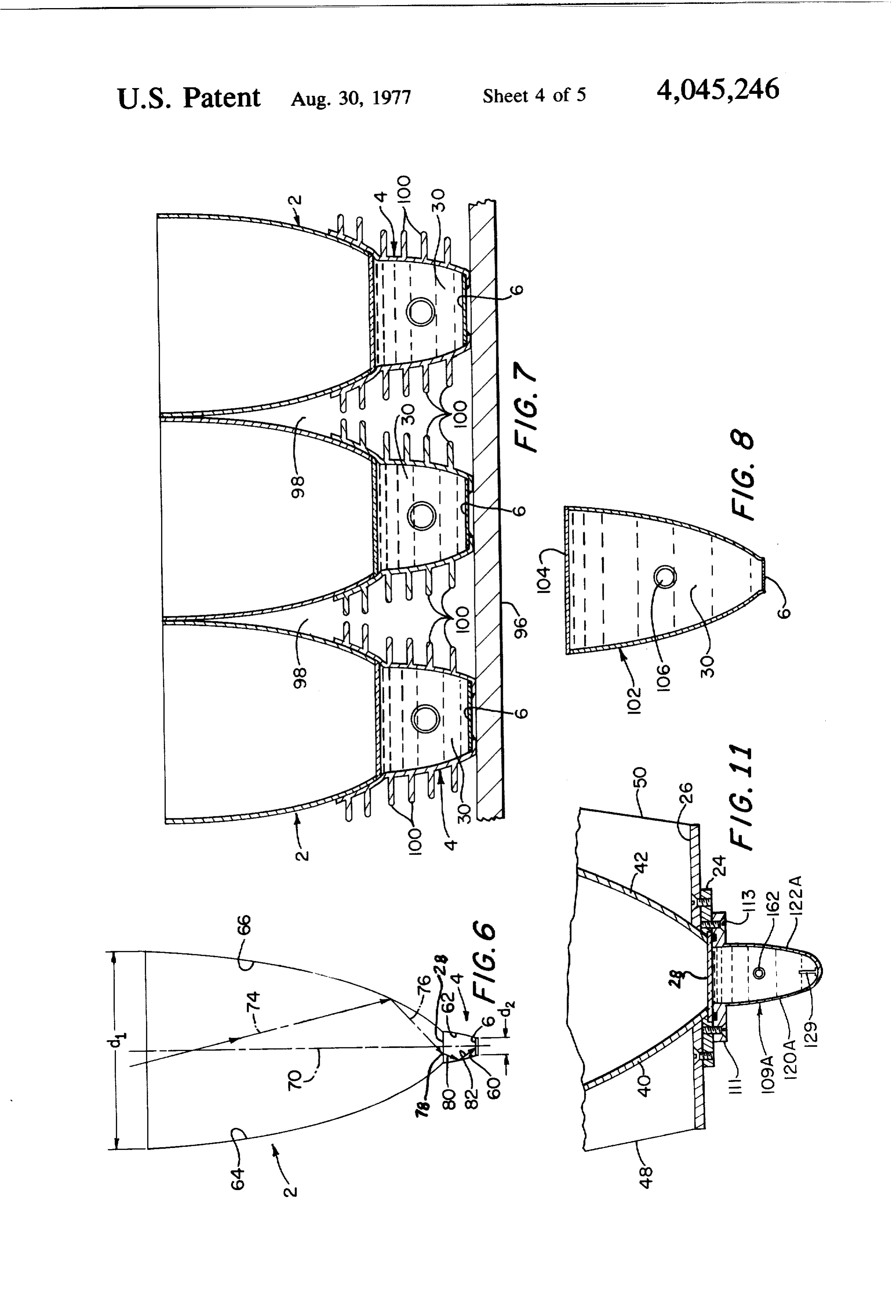
of the exterior circuit. A non-conducting potting com 25 8, F arc sin in 1/n. (3) pound 58 is applied to seal off the opening in bottom wall member 20 through which the terminal leads ex tend. where n, and nare respectively the indices of refraction The wall members of the upper and lower concentra of the medium in the upper concentrator, i.e., air, and tors may be made of various materials such as metal, 30 the cooling liquid 30 in the lower concentrator, and in wood or plastic. However, the inner surfaces of the wall is greater than in 1. The index of refraction of plate 28 members must be capable of acting as reflectors for may be ignored since, because it is relatively thin and solar radiation. This light-reflecting capability may be also flat on both sides, the plate has no concentrating achieved by applying a silver coating to the inner sur effect. With n exceeding n1, the light is concentrated by faces of the wall members. Preferably, however, the 35 the two concentrators by a factor of (n/n) (1/sin 8). wall members are made of aluminum and their inner FIG. 6 illustrates the path followed by a typical light surfaces are highly polished to a mirror finish. ray entering the entrance aperture of the upper concen Referring to FIGS. 2 and 4, the inner surfaces of the trator. The entering ray identified as 74 strikes the inner two concentrators preferably are shaped in accordance surface 66 of the upper concentrator and is reflected as with the teachings set forth by Dr. Roland Winston, shown by transit leg 76 down to the transparent plate Principles of Solar Concentrators of a Novel Design, Solar 28. Due to the difference in the refractive indices of Energy, Vol 16, pp, 89-95, Pergamon Press, 1974. Ac plate 28 and the air in the upper concentrator, the ray cordingly, the inner surfaces of end wall members 16, undergoes a change of direction as shown at 78 as it 18, 44 and 46 are flat and extend at a right angle to both passes through plate 28. It undergoes a further change the plane of the solar cell supporting panel 6 and the 45 of direction as it passes into cooling fluid 30 due to a longitudinal axis of groove 22, while the inner surfaces difference between the indices of refraction of plate 28 60, 6264 and 66 of side wall members 12, 14, 40 and 42 and cooling fluid 30. The light ray passes through fluid respectively each have a predetermined profile curva 30 as 80 and strikes the inner surface 60 of the lower ture. The upper and lower end edges of the inner sur concentrator where it is reflected as shown at 82 back faces of wall members 40, 42, 44 and 46 respectively 50 into the liquid and down through the exit aperture of define the entrance and exit apertures of the upper con the lower concentrator onto one of the solar cells of centrator and the upper and lower edges of the inner panel 6. By properly designing the two concentrators in surfaces of the side and end wall members 12, 14, 16 and the manner above described, the concentrator assembly 18 define the entrance and exit apertures respectively of can concentrate light on the solar cells by a factor of at the lower concentrator. In this connection it is to be 55 least 10, and if the concentrators are properly oriented, noted that the dimensions of the entrance aperture of such concentration is effected without the need for the lower concentrator are equal to or greater than the diurnal tracking as explained by Winston (supra). corresponding dimensions of the exit aperture of the Inasmuch as the tangent to the fully developed profile upper concentrator so as to maximize transmission of curve turns parallel to the optic axis at the upper edge, radiant energy into the lower concentrator, 60 the length of the collector can be shortened substan Referring now to FIG. 2, the predetermined profile tially below the value given in equation (2) with very curvature of the inner surface of side wall member 42 is little loss of entrance aperture. When the collector is a mirror image of the corresponding surface of side wall truncated, i.e. its length is shortened, the angular accep member 40. The predetermined profile curvature of tance is not diminished; only the concentration is each of said inner surfaces is that of a parabola with its 65 slightly reduced. Such shortening can result in signifi focus at the opposite edge of the exit aperture and its cant saving of material.
axis (identified as 68 for wall member 42) inclined at an In accordance with this invention, the conduits 36 angle 6 with respect to the center or optic axis 70 of and 38 are connected in a closed loop with a pump (not
Page 9
shown) and a cooling facility (also not shown) whereby which case it cools by transmitting heat from the solar cooling fluid is continually circulated through the cells on panels 6 to the walls of the lower concentrator. lower concentrator at a rate which assures that the FIG. 8 illustrates how cooling of the solar cells by a lower concentrator is kept filled. Any heating occur dielectric cooling medium can be achieved where the ring as a result of absorption of solar energy by either s solar cells are associated with a single concentrator. In the solar cells or the concentrators or as a result cf FIG. 8, the concentrator 102 is substantially the same as electrical resistance heating in the solar cells is rapidly the upper concentrator 2 of FIG. 1 except that it is filled compensated for by the circulating cooling fluid which with a dielectric cooling medium 30, its entrance aper picks up heat by conduction from the walls of the lower ture is closed off by a transparent glass or plastic cover concentrator and the solar cell panel and gives up such 10 plate 104, and the solar cell panel 6 is mounted in the heat when it is cooled in the cooling facility. The latter exit aperture of the concentrator. The plate 104 and may be a refrigeration type cooler or may be merely a panel 6 are hermetically sealed to the side and end walls simple heat exchanger wherein heat is removed by ex of the concentratorso as to prevent leakage of the cool change with a secondary cooling liquid or by radiation ing medium. The latter is circulated through the con to the atmosphere. In any event, the fluid 30 functions 15 centrator via conduits connected to ports 106 formed in as a light transmitting medium as well as a cooling me the end walls of the concentrators. In this case the angul dium. Obviously the heat transmitted to the coolant lar acceptance is increased because the index of refrac need not be discarded, but can be utilized in and of itself tion of the dielectric cooling medium (n2) exceeds that to provide hot water or space heating. of air (n). This increased angle of acceptance (6ma") is FIG. 5 illustrates how a number of the units shown in 20 given by the relation:
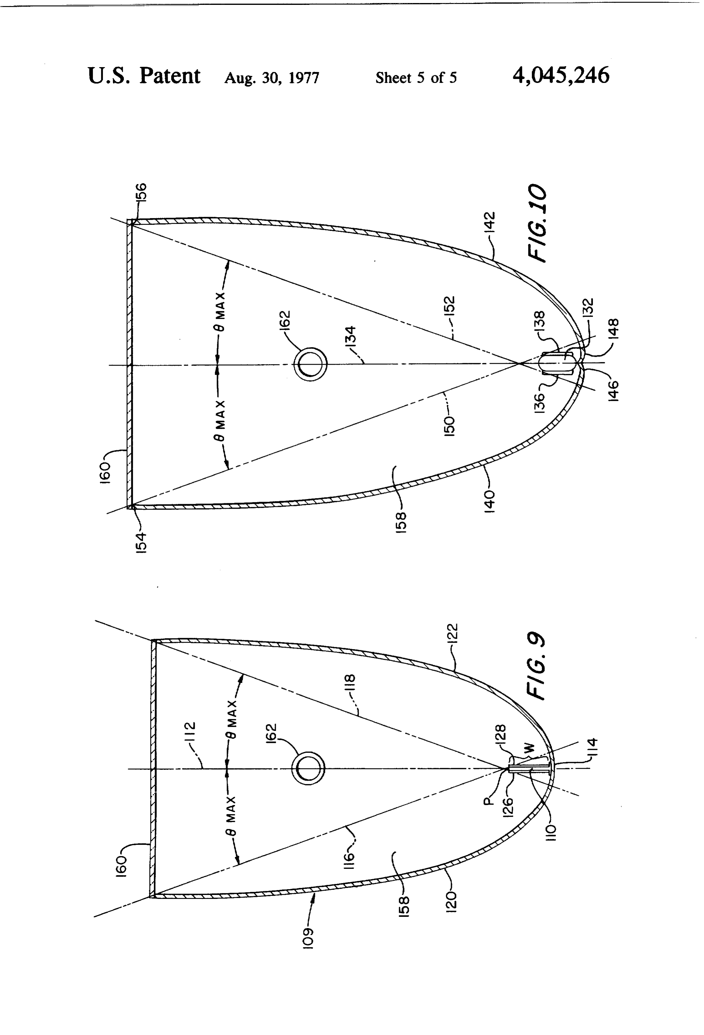
FIGS. 1-4 may be connected into a common coolant circulating system. In this case the several dual concen 6," as arc sin (n/n) sin 8) (4) trator assemblies are disposed side by side with their conduits 36 connected to an inlet manifold 84 and their where the angle 8 specifies the profile curve of the conduits 38 connected to an outlet manifold 86. Mani concentrator in the sense of equations (1) and (2). folds 84 and 86 are connected to a circulating pump 85 FIG. 9 illustrates a trough-like concentrator 109 hav and a cooling facility which is exemplified as a heat ing a flat solar cell support member 110 which extends exchanger 87, whereby coolant is continually circulated lengthwise of the concentrator and is disposed so that in a parallel mode through the several lower concentra its opposite sides extend parallel to and are equally tors via conduits 36 and 38 to absorb heat and through 30 spaced with the center or optic axis 112. The bottom the heat exchanger to give up the absorbed heat. By wall portion 114 of the concentrator extending between way of example, heat exchanger 87 may be of the type dashed lines 116 and 118 has the shape of an arc of a through which water is circulated to pick up heat, circle of radius W centered at P. The remaining side whereby it functions as a water heater with the heated wall portions 120 and 122 of the concentrator are parab water being usable for domestic or industrial purposes. 35 olas with foci at P, so that radiant energy received at an Of course, if desired, the coolant circulating system may angle 8 is reflected tangent to the upper edge of the be modified so that the coolant passes through the sev substrate which extends lengthwise of the concentrator. eral lower concentrators serially instead of in the paral Two solar cell panels 126 and 128 are mounted on oppo lel mode just described. An incidental advantage of a site sides of support member 110 so that they are in back multiple unit array as shown in FIG. 5 is that the adja 40 to back relation. With this arrangement, energy enter cent concentrator assemblies may be tied together, e.g., ing the collector between the dashed lines 116 and 118 by connecting together the ribs 48 of one assembly with at an angle less than 6 is directed onto one or the the ribs 50 of the adjacent assembly, so as to form an other of the solar cell panels.
integrated and strong structure. It is to be understood FIG. 10 illustrates a collector having a oval solar cell also that the solar cells associated with the several con 45 support member 132 centered on its optic axis 134. Solar centrator assemblies are interconnected electrically in cell panels 136 and 138 are mounted to the opposite parallel or series relation according to the power re sides of support member 132. The bottom wall portions quirements of a particular installation. Thus, by way of 146 and 148 extending between dashed shadow lines 150 example, if each panel 6 comprises a group of solar cells and 152 are involutes of the sides of the oval support interconnected in series, a parallel-series power matrix SO member 132. The remaining side wall portions 140 and may be achieved by coupling the several groups in 142 are so shaped as to reflect radiant energy incident at parallel between a pair of conductors 88 and 90 which angle 8 tangent to the oval. Terminal points 154 and connect the power matrix to an exterior circuit. 156 are points on the side walls 140 and 142 where the FIG. 7 shows a modification of the invention, In this tangent to the side wall is parallel to the optic axis 134. case the lower concentrators 4 are anchored to a sub 55 In this arrangement radiant energy entering the collec strate 96 and the upper ends of the adjacent side walls of tor between shadow lines 150 and 152 at an angle up to the upper concentrators engage and are secured to each but not exceeding 8 is reflected onto the solar cell other so as to form passageways 98 through which an panels.
auxiliary cooling medium such as air may be circulated As in the apparatus of FIG. 8, the ends of the concen to provide additional cooling of the concentrators. As a 60 trators shown in FIGS. 9 and 10 are closed off by verti further option, cooling fins 100 may be attached to the cal end walls 158 and the entrance aperture is closed off upper and/or lower concentrators to radiate heat away by a transparent glass or plastic cover plate 160. The from the concentrators. Fins 100 are made of a suitable cover plates are hermetically sealed to the side and end heat conductive material, e.g., aluminum, and may be walls of the concentrators so as to prevent leakage of attached in one of several ways known to persons the dielectric cooling medium, the latter being circu skilled in the art, e.g., by riveting or welding. In this lated through the concentrators via conduits connected modification the cooling medium 30 may be circulated to ports as shown at 162 formed in the end walls of the as previously described or it may be stationary, in concentrators.
Page 10
It is further contemplated that the lower stage of the Still other concentrators known to persons skilled in two-stage concentrator shown in FIGS. 1-3 may be the art may be used in practicing the invention. replaced by a concentrator-solar cell arrangement of What is claimed is:
the type shown in FIGS. 8, 9 or 10. 1. Apparatus for converting solar radiation to electri Two or more of the single stage concentrators shown 5 calenergy comprising means defining a closed chamber in FIGS. 8, 9 and 10 may be disposed side by side as with a wall capable of passing solar radiation, at least shown in FIGS. 5 and 7, with dielectric cooling fluid one solar cell disposed in said chamber, first solar radia circulated through them in parallel or in series as de tion concentrator means for receiving solar radiation sired. The solar panels of the several units may be con and directing it through said wall into said chamber, nected in parallel or series according to power require O said chamber comprising second solar radiation concen nents. trator means for directing said solar energy onto said at FIG. 11 shows how two groups of solar cells may be least one solar cell, and a cooling fluid in said chamber, mounted in a dual concentrator. In this case the upper said cooling fluid being (a) electrically non-conductive, concentrator is the same as the upper concentrator 2 of 15 (b) capable of passing said solar radiation to said at least FIGS. 1-4. However, the lower concentrator 109A is one solar cell, and (c) having a higher-than-air index of similar to the concentrator 109 of FIG. 10, with its side refraction.
and bottom wall portions 120A, 122A and 114A being 2. Apparatus according to claim 1 and further includ shaped in accordance with the teachings of R. Winston, fluidmeans ing for introducing and removing said cooling from said chamber.
Solar Energy, Vol. 17, No. 4, 1975, "Principles of Cy 20 3. Apparatus lindrical Concentrators for Solar Energy." Concentra solar radiation according to claim 1 wherein said first tor 109A is provided with flanges 111 along its top trough having aconcentrator top end and means is an elongated a bottom end, and said edges which are secured to the mounting plate 24 by screws 113. The transparent plate 28 is sandwiched chamber is located at said bottom end. between the upper and lower concentrators and her 25 at 4.said Apparatus according to claim 3 wherein said wall is bottom end of said trough.
metically seals off the lower concentrator so that the 5. Apparatus according to claim 3 wherein said at latter may be filled with a dielectric cooling fluid via least one solar cell is spaced from said wall. conduits connected to ports 162 in the two end walls. 6. Apparatus according to claim 6 wherein said wall Mounted to the inner surface of bottom wall portion and said solar cell are disposed parallel to one another. 114A is a dual solar cell assembly represented schemati 30 7. Apparatus according to claim 1 wherein said first caily at 129. It is to be understood that the assembly 129 concentrator means comprises opposed parabolically comprises two solar cell panels corresponding to solar shaped walls forming a trough having a top end, a bot cell panels 126 and 128 of FIG. 9 mounted in back-to ton end and an entrance aperture at said top end and an back relation on opposite sides of a support member exit aperture at said bottom end, and further wherein corresponding to support member 110 (also FIG. 9). As 35 said chamber is disposed at said exit aperture. in the arrangement of FIG. 9, the dual solar cell assem 8. Apparatus according to claim 7 wherein said sec bly 129 extends lengthwise of the concentrator and is ond concentrator means comprises opposed paraboli disposed so that the two solar cell panels extend parallel cally shaped walls of said chamber forming a trough to and are equally spaced with respect to the center or having a top end adjacent to said exit aperture. optic axis of the lower concentrator, With this arrange 9. Apparatus according to claim 7 wherein said solar ment, light received from the upper concentrator is cell is spaced from said exit aperture.
reflected onto the light sensitive surfaces of the back-to 10. Apparatus for converting solar radiation to elec back solar cell panels in the same manner as is accom trical energy comprising means defining a closed cham plished with the concentrator of FIG. 9. ber with an entrance aperture capable of passing solar While the coolant 30 may be a gas, it is preferred that 45 radiation, said chamber including walls adapted to re it be a liquid since a gas is incapable of removing heat as flect said solar radiation onto a predetermined position, efficiently as a liquid. However whether it is a gas or a at least one solar cell disposed in said chamber in said liquid, the coolant must be a dielectric or non-conduc position to receive said radiation, and a cooling fluid in tor of electricity since otherwise it might short-circuit said chamber in contact with said at least one solar cell, the solar cells. Also, the coolant must be transparent to SO said cooling fluid being (a) electrically non-conductive, solar energy radiation (or at least to visible and ultravio (b) capable of transmitting solar radiation from said let light). It also is essential that the coolant be a mate entrance aperture to said at least one solar cell, and (c) rial which will not corrode or otherwise attack the solar having a higher-than-air index of refraction. cells or the collectors. By way of example, the coolant 11. Apparatus according to claim 10 wherein said 30 may be ethylene glycol or distilled water. 55 chamber has an exit aperture and said at least one solar The invention is not limited to concentrators of the cell is disposed at said exit aperture. type hereinabove described. Instead, for example, the 12. Apparatus according to claim 10 wherein a sec concentrator may be the so-called Schumann type tion of at least one of said walls has a parabolic curva wherein the sides of the trough-like concentrators are ture.
flat inclined mirrors.
Provenance
- Collection
- Cited prior art
- Original PDF
- patentimages.storage.googleapis.com →
- Filed
- 1975-08-11
- Pages
- 10
- Method
- pdftotext (the PDF's own text layer) + pdftoppm 300dpi page scans
- Source
- Google Patents bibliographic record
- Granted
- 1977-08-30
- Inventors
- Abraham I. Mlavsky; Roland Winston; Mobil Tyco Solar Energy Corp
- Transcribed from
- patentimages.storage.googleapis.com →