patent · US4141326
Closed loop control system for hydrogen fuelled engine
27 February 1979
Page 1 — bibliographic record
United States Patent (19) 11) 4,141,326 Wober 45) Feb. 27, 1979 (54) CLOSED LOOP CONTROL SYSTEM FOR Primary Examiner-Wendell E. Burns HYDROGEN FUELLED ENGINE Attorney, Agent, or Firm-James R. Ignatowski; Russel C. Wells 75) Inventor: William G. Wolber, Southfield, Mich.
73 Assignee: The Bendix Corporation, Southfield, (57) ABSTRACT Mich.
Disclosed herein is a closed loop fuel control system for 21) Appl. No.: 776,793 a hydrogen fuelled engine embodying a hydrogen sen 22 Filed: Mar. 11, 1977 sor in the exhaust manifold to provide a feedback signal indicative of the quantity of unburned hydrogen in the 51) Int. Cl? ................................................ FO2B3/00 engine's exhaust. The system electronically controls or 52 U.S. C. ..................... 123/119 EC: 123/DIG. 12; trims the fuel delivery to the engine in response to sig 123/119 E; 123/120; 123/32 EE nals indicative of the engine's operating parameters and 58) Field of Search ............... 123/DIG. 12, 3, 119 E, the signal generated by the hydrogen sensor to maintain
the concentration of hydrogen in the exhaust at a prede 56) References Cited termined level.
4,043,300 8/1977 Lombard ......................... 123/32 EE 33 Claims, 11 Drawing Figures
CONTROL
UNIT
REGULATED
SOURCE
Page 2
Drawing sheet — no readable text.
Page 3
Drawing sheet — no readable text.
Page 4
Drawing sheet — no readable text.
Page 5
Drawing sheet — no readable text.
Page 6
FIG. 8
TRGGER SIGNALS --
DELAY PULSES P
VOLTAGE B D TO B D B D
CAPACTOR C F. C.' c
NJECTION o
PULSES
PRESSURE
THRESHOLD
voLTAGE OF
NJECTION
PULSES
EXCESSIVE H2 DETECTED
NORMAL
NSUFFICIENT H2 DETECTED
AND WARM UP ENRICHMENT
Page 7
Drawing sheet — no readable text.
Page 8
Another object of the invention is a closed loop fuel
CLOSED LOOP CONTROL SYSTEM FOR control system for a hydrogen fuelled engine using a HYDROGEN FUELLED ENGINE hydrogen sensor to detect the quantity of unburned BACKGROUND OF THE INVENTION hydrogen in the engine's exhaust. Still another object of the invention is a closed loop 1. Field of the Invention fuel control system for a hydrogen fuelled engine in The invention relates to fuel control systems and, in which the quantity of unburned hydrogen is maintained particular, to a closed loop fuel control system for an at a predetermined level.
internal combustion engine using hydrogen as a fuel. Another object of the invention is a closed loop fuel 2. Prior Art O control system for a hydrogen fuelled engine in which Presently internal combustion engines use fossil or an enriched fuel mixture is provided during the transi hydrocarbon type fuels. The world supply of fossil tional warm-up period.
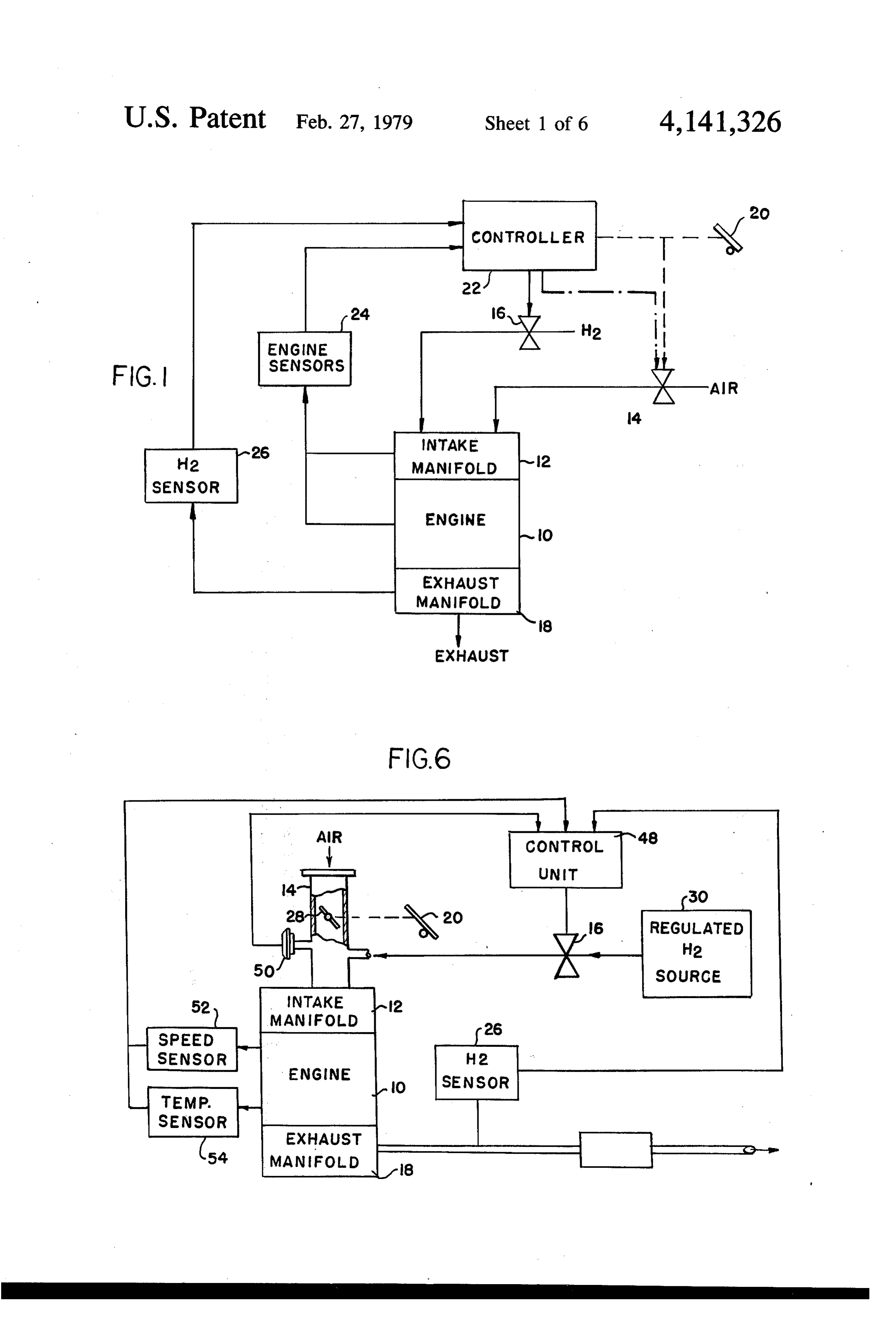
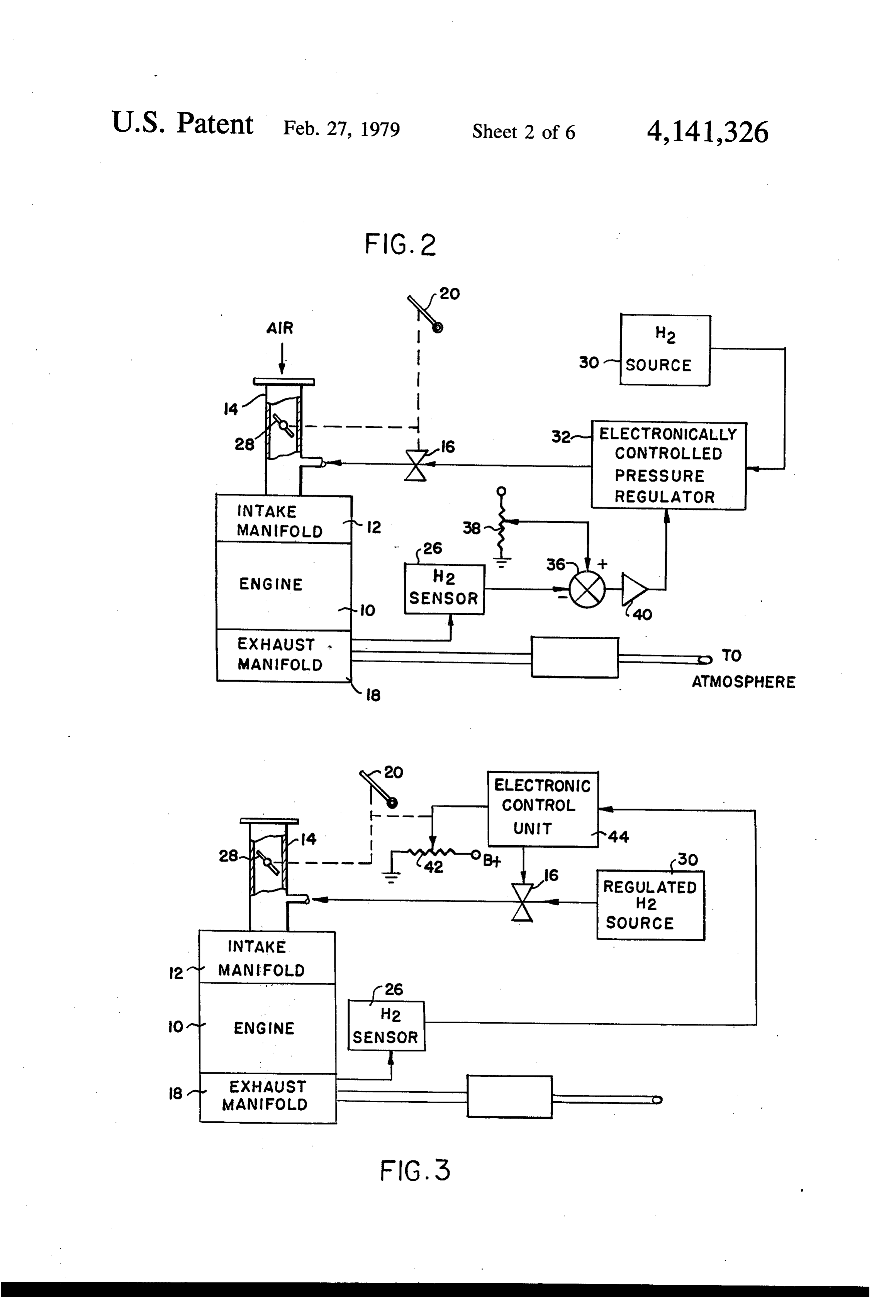
fuels, as we know, is limited and already the scientific These and other objects will become apparent from community is looking at alternatives to the hydrocar reading the detailed description of the preferred em bon fuels. Added to this, ecological problems stemming 15 bodiment in conjunction with the drawings. from the widespread use of hydrocarbon fuels is hasten BRIEF OESCRIPTION OF THE DRAWENGS ing the development of alternate relatively pollution free alternates. One of the primary candidates as an FIG. 1 is a block diagram of the closed loop fuel alternate fuel is hydrogen, which is in abundant supply, control system for a hydrogen fuelled engine. and its by-product of combustion is water, which is not 20 FIG. 2 is a first embodiment in which the feedback considered as a pollutant. Considerable research using from the hydrogen sensor controls the pressure of the hydrogen as a fuel is underway and operative engines hydrogen fuel.
using hydrogen as a fuel have been built and tested. The FIG. 3 is a second embodiment using an electronic use of hydrogen as a fuel is taught by Billings in U.S. control unit receiving inputs from a throttle position Pat. No. 3,983,882 (October 1976). This concept was 25 sensor and the hydrogen sensor.
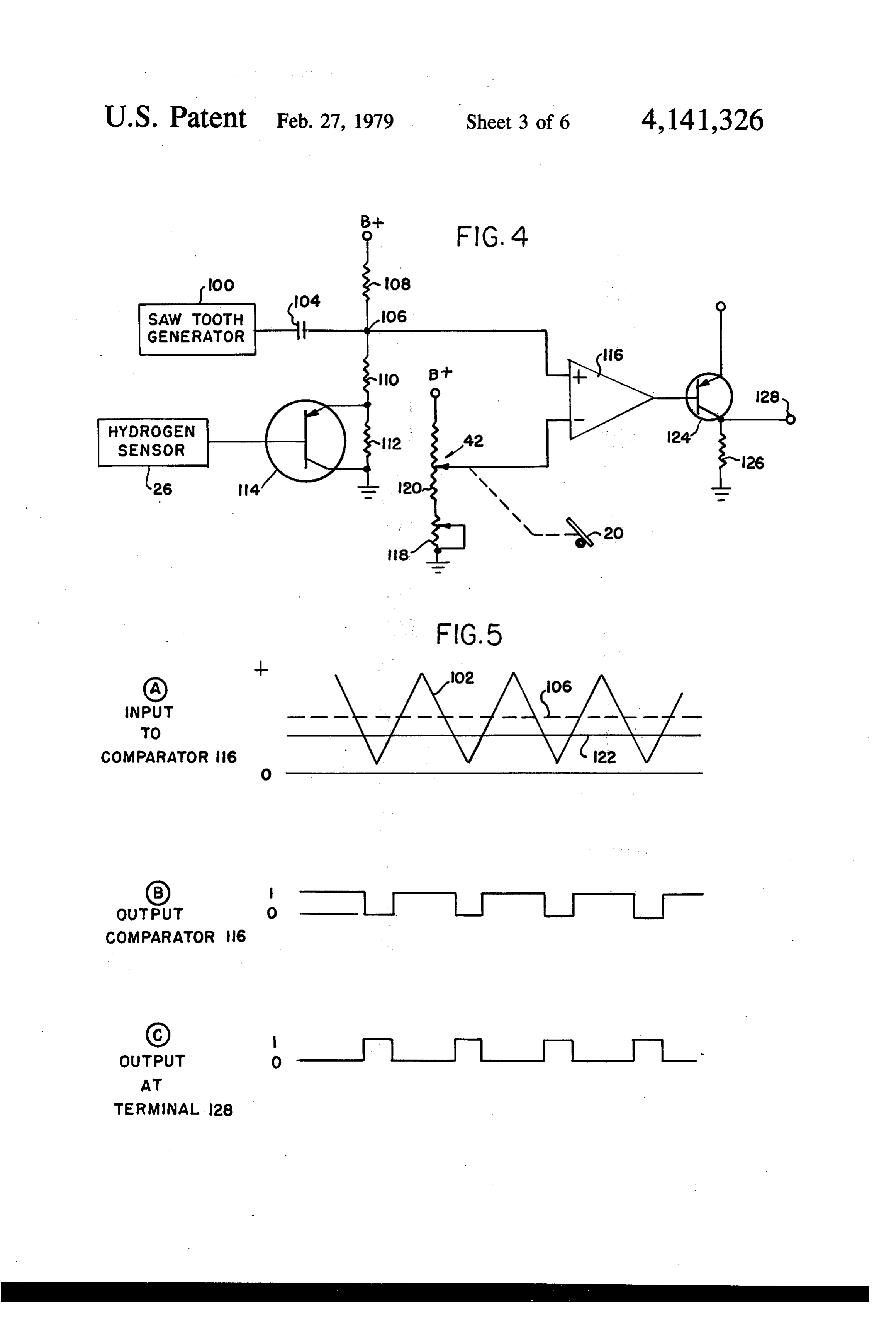
also taught by A. F. Bush and W. D. Van Vorst in a FIG. 4 is a circuit diagram of the electronic unit of paper presented at the Cryogenic Conference, Aug. FG, 3.
8-10, 1973 from Advances in Cryogenic Engineering FIG. 5 is waveforms used in the description of the Underwood in U.S. Pat. No. 3,862,624 (January 1975) circuit diagram of FIG. 4.
and Smith in U.S. Pat. No. 3,608,529 (September 1971) 30 FIG. 6 is a block diagram of the preferred embodi also teach the use of hydrogen as a fuel. The hydrogen ment of the closed loop fuel control system having an fuelled engine systems taught by the prior art cited electronic control unit receiving inputs from engine above are open loop systems and must be periodically sensors and the hydrogen sensor.
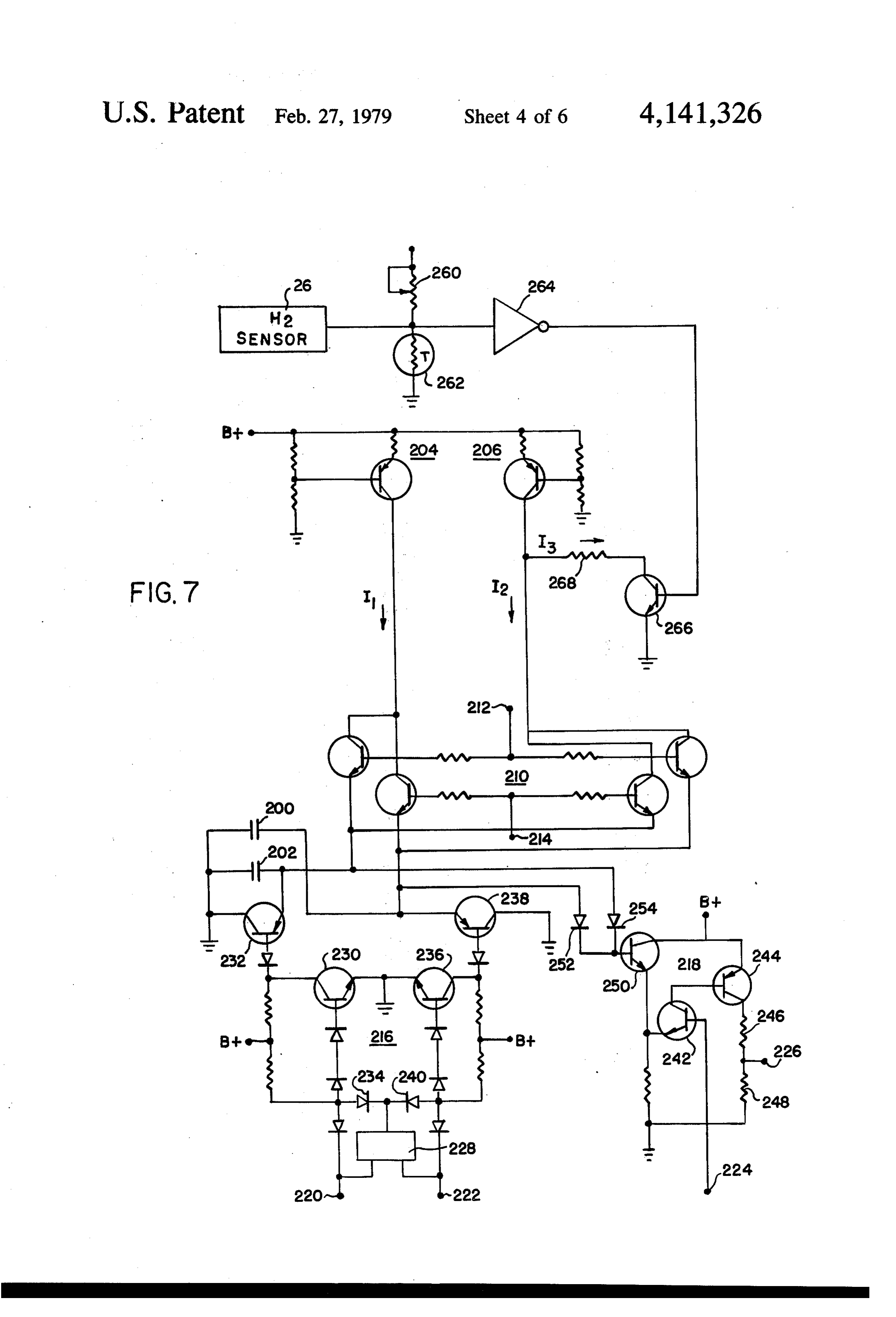
adjusted to assure optimum performance and optimum F.G. 7 is a schematic of the electronic control unit of fuel economy. 35 FG, 6,
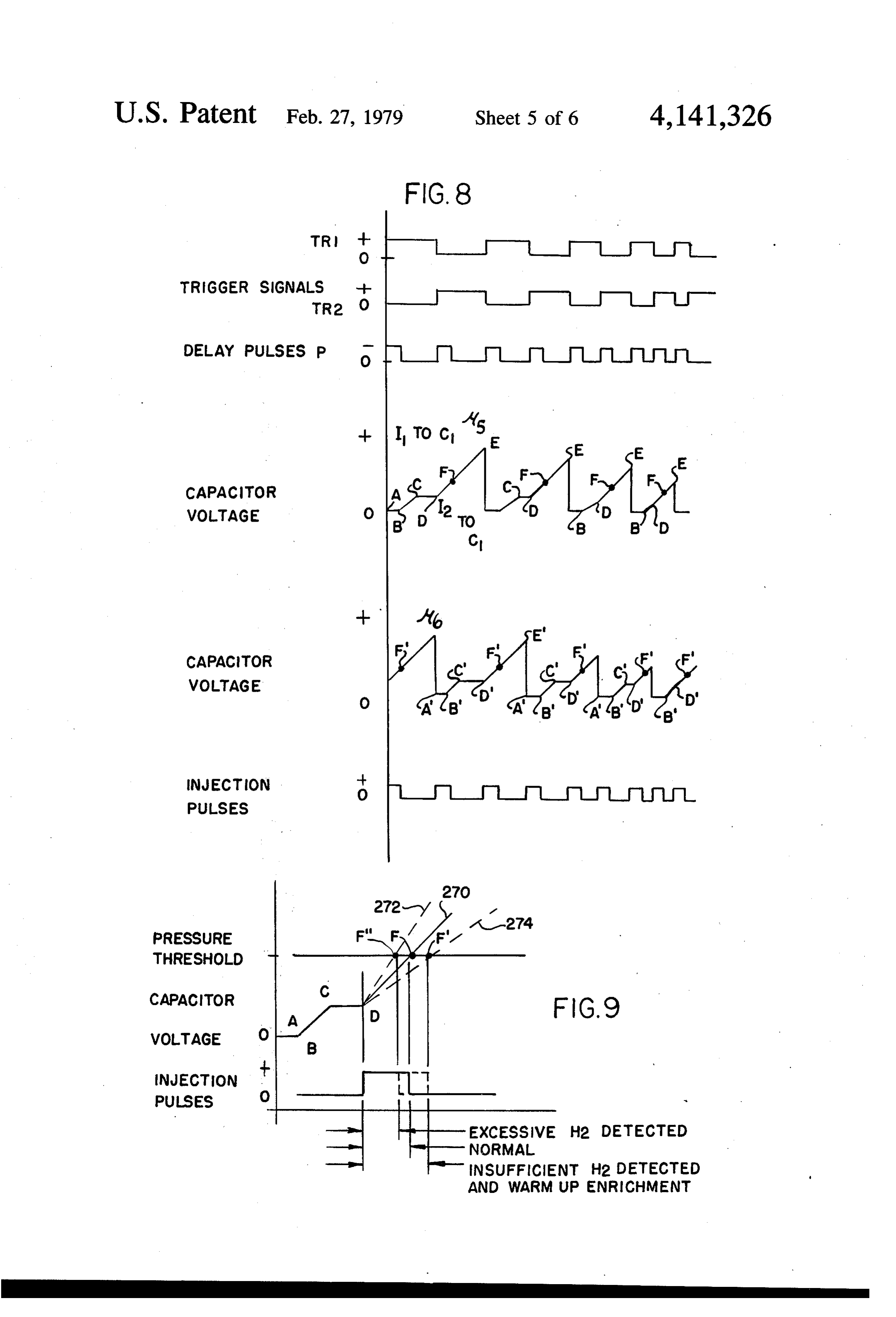
The more advanced electronically controlled fossil FIG. 8 is waveforms used in the description of the fuel systems are tending towards closed loop systems in schematic shown on FIG. 7.
which the oxygen content of the exhaust is continuously FIG. 9 is a waveform used in the description of the monitored to provide a correction to the quantity of operation of the feedback portion of the electronic con fuel being delivered to the engine to compensate for 40 trol unit shown in FIG. 7.
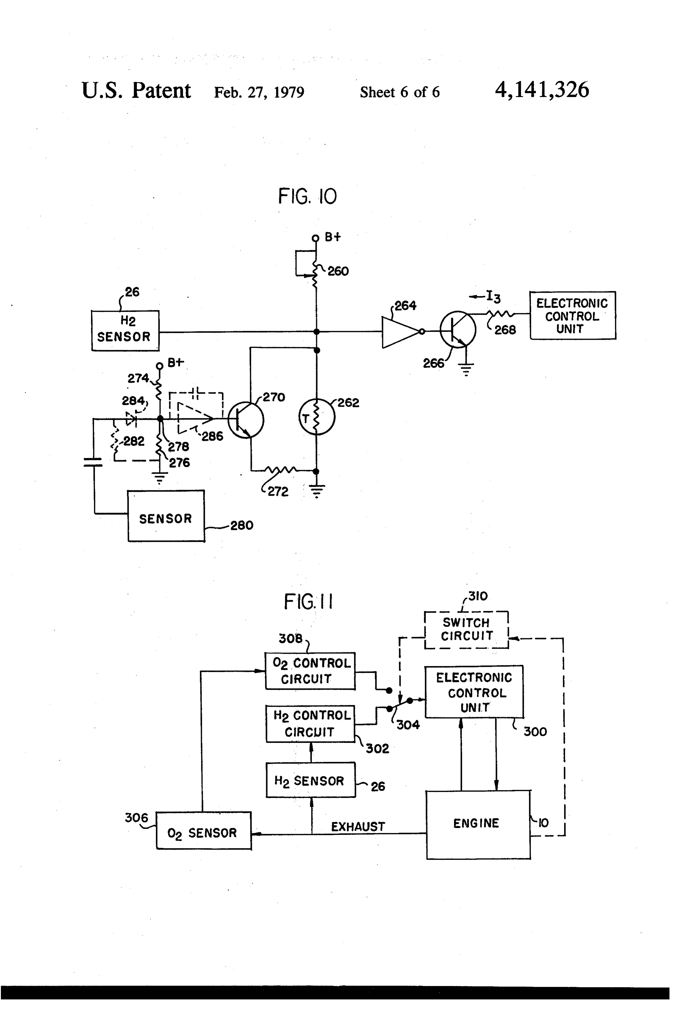
degradation, wear, or other changes in the engine's FIG. 10 is an electrical schematic of an alternate fuel/air delivery system, as well as for subtle changes in embodiment providing for fuel enrichment during a the operating characteristics of the engine. A typical transient mode of operation.
example of one such closed loop electronically con FIG. 11 is an alternate embodiment including an trolled fossil fuel system is taught by Seitz in U.S. Pat. 45 oxygen closed loop system to provide for lean operation No. 3,815,561 (June 1974). under selected conditions.
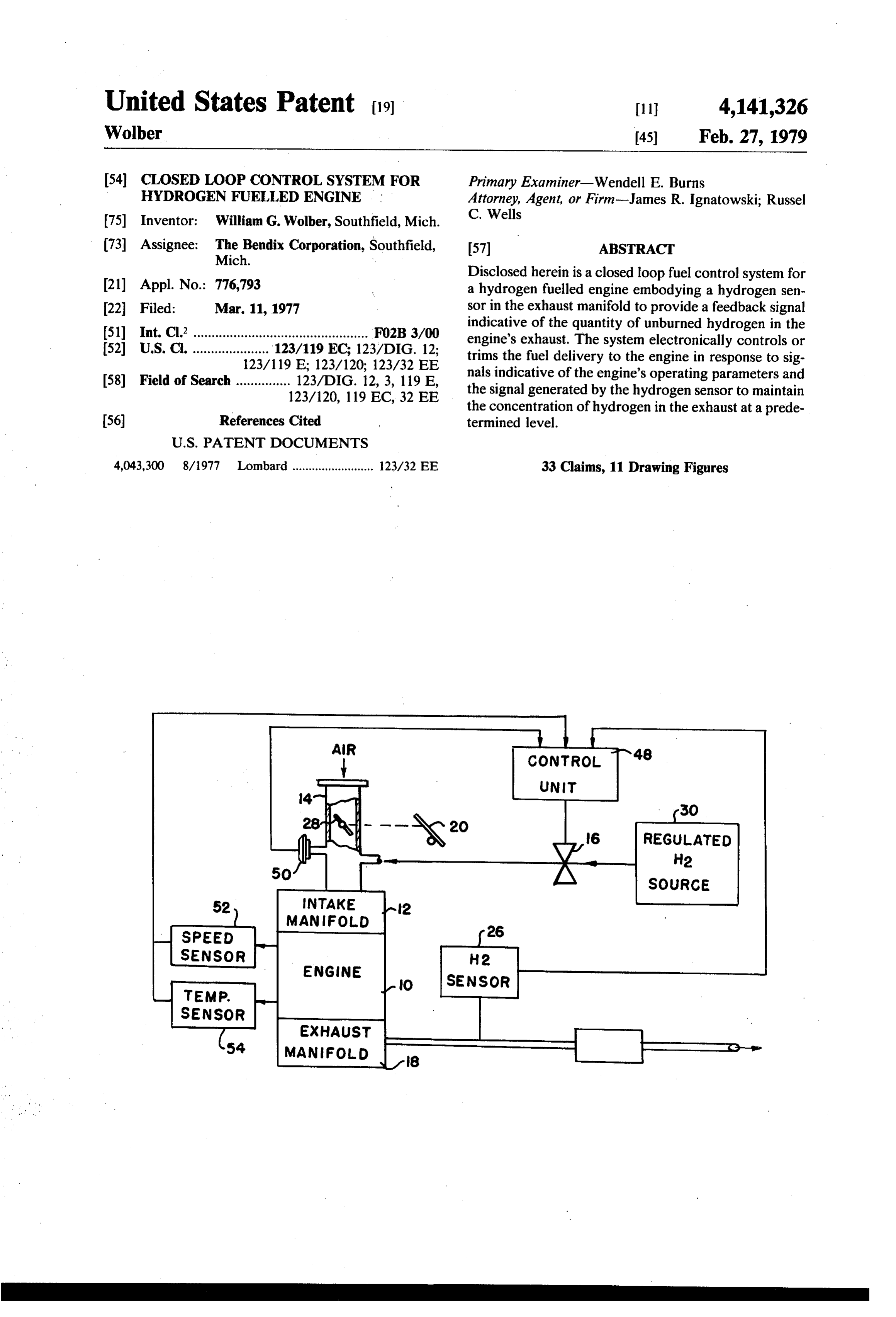
The present invention is a closed loop electronic DESCRIPTION OF THE PREFERRED control system for a hydrogen fuelled engine using a EMBODIMENT sensor detecting the quantity of unburned hydrogen in the engine's exhaust. 50 The basic concept of the closed loop fuel control system for a hydrogen fuelled engine is shown in FIG.
SUMMARY OF THE INVENTION 1. An engine 10 has an intake manifold 12 receiving a The invention is a closed loop fuel control system for controlled quantity of air or oxygen from an external a hydrogen fuelled engine using a sensor generating a source through an air control valve 14 and a controlled feedback signal indicative of the quantity of unburned 55 quantity of hydrogen fuel through a fuel control valve hydrogen in the exhaust gas emitted by the engine. The 16. The exhaust gases generated by the engine 10 are quantity of fuel delivered to the engine is electronically emitted into an exhaust manifold 18 prior to being ex controlled in response to inputs indicative of the quan hausted to the atmosphere. The air control valve 14 tity of air being delivered, as well as other operating may be a typical butterfly valve, as used in contempo parameters of the engine. A hydrogen sensor monitors rary automotive internal combustion engines, or may be the composition of the exhaust gas, and generates a of any other known configuration. The air control feedback signal indicative of the quantity of unburned valve may be operator-actuated by means of a suitable hydrogen. The feedback signal is applied to the fuel control, such as the conventional accelerator foot pedal delivery system and modifies the fuel being delivered to 20, or may be indirectly controlled by servo mecha maintain a predetermined quantity of unburned hydro 65 nisms responding to the signals generated by an elec gen in the exhaust. tronic control unit, such as controller 22, as is well The object of the invention is a closed loop fuel con known in the art. Fuel delivery is controlled by a fuel trol system for a hydrogen fuelled engine. control valve 16 in response to signals generated by
Page 9
controller 22. The controller 22 may receive inputs trolled pressure regulator 22, which is operative to from the accelerator foot pedal 20, as well as engine increase or decrease the pressure of the hydrogen gas sensors 24 generating signals indicative of the engine's being communicated to the input of control valve 16. operating parameters. The engine sensors 24 may com The operation of the embodiment shown in FIG. 2 is prise a mass air flow sensor generating a signal indica as follows: The position of the air control valve 14 and tive of the quantity of air flow to the engine through the hydrogen control valve 16 are controlled directly by intake manifold or, alternatively, an engine speed sensor the actuation of the operator's pedal and, therefore, generating a signal indicative of the engine speed and an predetermined quantities of hydrogen and air are admit intake manifold pressure sensor, or any other sensor ted to the engine's intake manifold. The hydrogen and detecting an engine operating parameter which may be O air are mixed, then inhaled by the engine where the utilized in the controller for computing the amount of mixture is burned in a conventional manner to produce required fuel. The controller 22 also receives an input the desired mechanical motion. The burned exhaust from a hydrogen sensor 26 detecting the quantity of gases are emitted into the exhaust manifold 18 wherein hydrogen present in the exhaust gases in the exhaust the hydrogen sensor 26 detects the concentration of manifold 18. The hydrogen sensor 26 may be of the type 15 unburned hydrogen and generates a signal indicative of disclosed by C. C. Matle etal in U.S. Pat. No. 3,242,717 the hydrogen concentration. This signal is negatively (March 1966). This sensor utilizes a palladium sensor summed with the set point signal to produce a compos film which changes its electrical conductivity upon ite signal, which when amplified by the buffer amplifier exposure to hydrogens in an amount corresponding to 40, produces a signal controlling the pressure at the the concentration of hydrogen passing over the palla 20 output of the pressure sensor 32. Since the quantity of dium film. hydrogen flowing through the fuel control valve 16 is a The operation of the system is as follows: The con function of both the pressure differential across the fuel troller 22 responds to the input from the operator control valve and the input from the accelerator pedal through the accelerator pedal 20 and/or the engine's 20 controlling the pressure effectively controls the sensors 24 and generates a control signal indicative of 25 quantity of fuel being delivered to the engine. When the the required quantity of hydrogen and/or air to be ad detected quantity of hydrogen in the exhaust gas is less mitted into the engine, which actuates the hydrogen than the predetermined amount, the output of the hy control valve 16 and/or air valve 14 to pass the com drogen sensor 26 is indicative of the decrease in hydro puted quantity of hydrogen and air to the engine. The gen content. Since the output of the hydrogen sensor hydrogen/air mixture is burned in the engine to pro 30 has decreased, the output of the sum amplifier 36 in duce a desired mechanical motion, as in a conventional creases. This signal, amplified by the buffer amplifier 40, internal combustion engine, and the burned gases are causes the electronically controlled pressure regulator emitted into the exhaust manifold. The hydrogen sensor 32 to increase the pressure at the input end of the hydro detects the quantity of unconsumed hydrogen in the gen valve 16 and the quantity of hydrogen input to the exhaust gases and generates a signal which corrects the 35 engine is increased. Conversely, when the hydrogen signals generated by the fuel delivery controller 22 so content in the exhaust gases is greater than the predeter that the quantity of unburned hydrogen in the exhaust mined amount, the output of the hydrogen sensor 26 gases has a predetermined value. As used herein, the increases. This increased output of the hydrogen sensor, term "air" includes the possibility of using relatively when negatively summed with the input from the set pure oxygen gas rather than atmosphere air as the oxi point generator 38 in the sum amplifier 36, results in a dizing agent for the hydrogen fuel. decreased signal which causes the electronically con A simplified version of the closed loop hydrogen fuel trolled pressure regulator to decrease the pressure at the control system is illustrated in FIG. 2. The system com input side of valve 16 and consequently decreasing the prises an engine 10 having an intake manifold 12 and an quantity of fuel delivered to the engine. exhaust manifold 18, as previously discussed with refer 45 A slightly different embodiment of the closed loop ence to FIG. 1. Air is emitted into the intake manifold hydrogen fuel control system is illustrated in FIG. 3. As via the air control valve illustrated as a butterfly valve in previous illustrations, the system comprises an engine 28 controlled by mechanical linkages from the opera 10 having an intake manifold 12 and an exhaust mani tor's foot pedal control 20. The foot pedal 20 also actu fold 18. Air is emitted into the intake manifold via the ates the hydrogen control valve 16 by suitable mechani 50 air control valve 14 having a butterfly 28 controlled cal linkages to simultaneously provide a proportional through mechanical linkages by the operator's foot quantity of hydrogen fuel to the engine. The hydrogen pedal 20. The operator's foot pedal also actuates the control valve 16 may be coordinated directly with the movable contact of a potentiometer 42 and is shown to operation of the butterfly valve 28 or may be controlled provide an electrical input to an electronic control unit through separate linkages. Hydrogen fuel from a hydro 55 44. The electronic control unit 44 also receives an input gen fuel storage 30 is communicated to the input of an from the hydrogen sensor 26 and generates an output electronically controlled pressure regulator 32. The signal which controls the actuation of hydrogen control output of the pressure regulator 32 is communicated to valve 16. Hydrogen fuel from a hydrogen source 30 is the inputside of the hydrogen fuel control 16, as shown. received at the input of the hydrogen valve 16. The The hydrogen content in the exhaust gas is monitored output of valve 16 is connected to the intake manifold by the hydrogen sensor 26 which generates an output via the valve 14.
signal indicative of the concentration of hydrogen in the The operation of the circuit is as follows: The air flow exhaust gas. A sum amplifier 34 combines the output to the engine is controlled directly by the operator's signal from the hydrogen sensor with a set point signal foot pedal 20 which also controls the position of the generated by a set point generator illustrated as a vari movable contact of variable potentiometer 42 generat able potentiometer 36. The combined signal from the ing a first signal indicative of the quantity of air being sum amplifier 34 is amplified in a buffer amplifier 36 supplied to the engine. The hydrogen sensor 26 gener prior to being communicated to the electronically con ates a signal indicative of the hydrogen content of the
Page 10
gas in the exhaust manifold. The electronic control unit width of the pulses at output terminal 128 increases. 44 responds to both of these signals and generates an These pulses at output terminal 128 may control a sim output signal which controls the actuation of valve 16. ple ON-OFF hydrogen control valve 16 or a propor When the hydrogen content of the exhaust gases is less tional control valve, as are known in the art. than desired, the signal generated by the hydrogen sen When the hydrogen content of the exhaust gas in sor decreases. A decreased input from the hydrogen creases, the output signal generated by the hydrogen sensor causes the electronic control unit 44 to generate sensor increases. This increased output signal applied to signals actuating valve 16 to increase the delivery of the base of transistor 114 decreasing its conduction and hydrogen gas to the engine. Conversely, when the hy increasing the potential at junction 106. This effectively drogen content of the exhaust gas is higher than the O displaces the whole sawtooth wave in a positive direc predetermined value, the increased output of the hydro tion. The positive portion of the square wave generated gen sensor 26 causes the electronic control unit togen by the comparator 116 will increase and the positive erate output signals actuating hydrogen control valve portion of the square wave at the output terminal will 16 to decrease the delivery of hydrogen fuel to the decrease, resulting in a decrease in the quantity of hy engine. 15 drogen supplied to the engine by valve 16. The control unit 44 may take many forms. One em Conversely, if the hydrogen content of the exhaust bodiment of such a control unit capable of performing gas decreases, the output of the hydrogen sensor will the desired functions is described with reference to the decrease, thereby increasing the conductance of transis circuit diagram shown on FIG. 4 and the waveforms tor 114 and lowering the bias potential at junction 106. shown on FIG. 5. A sawtooth generator 100 generates 20 The sawtooth wave will be displaced downward a sawtooth wave 102 shown on FIG. 5 having a prede towards ground and the positive portion of the square termined frequency and a predetermined peak to peak wave at the output terminal 128will increase causing an value. The sawtooth wave 102 is passed by a capaci increased fuel delivery to the engine. It would be evi tance 104 to junction 106 of a bias control network dent to one skilled in the art that the control functions of comprising serially connected resistances 108, 110, and 25 embodiment shown on FIG. 3 could be reversed and 112 connected between a source of electrical power that foot pedal 20 could directly control the actuation of designated B-- and ground. The B- and ground sym hydrogen control valve ió. The signals generated by bols have their conventional meaning. A transistor 114 the electronic control unit 44 would then control the has its emitter connected to the junction between resis actuation of the air control valve 14. tances 110 and 112 and its collector connected to 30 A more sophisticated embodiment of the closed loop ground. The base of transistor 114 receives the signal hydrogen fuel control system is illustrated in FIG. 6. An generated by the hydrogen sensor 26. The potentiome engine 10 having an intake manifold 12 and exhaust ter 42 is shown to comprise serially connected variable manifold 18 receives air or oxygen from an air control resistance 118 and potentiometer 120 having a movable valve 14, such as butterfly valve 28 controlled in re contact 122 actuated by the operator's foot pedal 20. 35 sponse to the actuation of an operator's accelerator Junction 106 and movable contact 122 are connected to pedal 20, Hydrogen fuel is supplied to the intake mani the inputs of comparator 116 and the output of compar fold from a regulated source of hydrogen 30 by means ator 116 is connected to the base of an output transistor of electrically controlled valve 16 activated in response 124. The emitter of transistor 124 is connected directly to signals from an electronic control unit 48. Control to B+ and the collector is connected to ground through unit 48 also receives inputs from a pressure sensor 50, a resistance 126 and to the output terminal 128. speed sensor 52, a temperature sensor 54, and a hydro The operation of the circuit is as follows: Considering gen sensor 26. Electronic control unit 48 responds to first the operation when the output of the hydrogen these inputs and generates signals controlling the deliv sensor 26 is constant and indicative of the desired quan ery of the hydrogen fuel to the engine. The control unit tity of hydrogen in the exhaust gas, the output of the 45 48 may be embodied in an analog or digital form, as is hydrogen sensor 26 applied to the base of transistor 114 known in the art.
causes transistor to conduct forming a parallel current The operation of the system is as follows: Air is emit path around resistance 112 effectively setting the bias ted to the intake manifold by means of valve 4 under potential at junction 106. The sawtooth waveform gen direct control of the operator by means of foot pedal 20. erated by the sawtooth generator 102 is passed by ca 50 The electronic control unit, in response to the inputs pacitance 104 and is applied to the positive input to from the pressure sensor, speed sensor and temperature comparator 116. The maximum and minimum peak sensor, compute the required amount of fuel required values of the sawtooth wave at the input of the compar by the engine and generates a signal controlling the ator, with reference to ground (0) potential, is deter actuation of the electronically controlled valve 16. As mined by the value of the bias potential at junction 106. 55 previously discussed with reference to FIGS. 2 and 3, The output of the movable contact 122 of potentiometer the hydrogen sensor detects concentration of hydrogen is applied to the negative input of comparator 116. The in the exhaust gases and generates a signal indicative of output of the comparator 116 is a square wave, as the hydrogen concentration in the exhaust manifold. shown on waveform B of FIG. 5. This square wave The output of the hydrogen sensor 26 is applied to the output of comparator 116, when applied to the base of 60 control unit and modifies the signal generated in re transistor 124, produces a complementary square wave sponse to the pressure sensor, speed sensor and tempera signal at the output terminal 128, as shown on wave ture sensor. When the quantity of hydrogen gas in the form C of FIG. 5. The variable resistance 118 deter exhaust gas is less than the desired amount, the output of mines the minimum value of the signal at movable the hydrogen sensor causes the control unit 48 to in contact 122 when the operator's pedal 20 is in its rest or 65 crease the quality of hydrogen being supplied to the idle position and functions as an idle control. It is al engine. Alternatively, when the quantity of hydrogen in ready seen that as the potential movable contact 122 the exhaust gas is greater than the predetermined increases in response to depressing the foot pedal 20, the amount, the output of the hydrogen sensor causes the
Page 11
control unit 48 to decrease in the quantity of hydrogen the trigger signals reverse polarity, the two capacitors being delivered to the engine. are charged by the alternate current source. In an alternate embodiment (not shown) the position The leading edges of the trigger signals TR1 and of the foot pedal 20 may be indicative of a desired en TR2, applied to the discharge circuit 216, activates a gine torque. In this embodiment, a signal indicative of 5 delay pulse generator 228, such as a single shot multivi the foot pedal is input directly into the control unit 48 brator which generates a delay pulse "p" having a pre and the control unit computes both the quantity of air determined pulse width significantly shorter than pulse and fuel to be admitted to the engine, as taught by Zech width of the trigger pulse. A positive trigger signal on nail in U.S. Pat. No. 3,750,632 (August 1973). Servo input terminal 220 coincident with the positive delay systems then control the actuation of both the air con 10 pulse signal "p' removes the effective ground potential trol valve 14 and the fuel control valve 16 in response to on the base of transistor 230 causing it and transistor 232 signals generated by the control unit. The output signal to conduct. Transistor 232 discharges capacitor 202 to of the hydrogen sensor 26 may also be input to the near ground potential during the period of the delay control unit 48 to correct or trim the quantity of hydro pulse. Termination of the delay pulse returns a ground gen fuel or air emitted to the engine, as discussed with 15 potential at the output of the delay pulse generator 228 reference to FIG. 6. which is applied to the base of transistor 230 through A circuit implementation of the control unit 48 of diode 234. The ground signal at its base blocks transistor FIG. 6 is illustrated in FIG. 7. The basic electronic 230 which in turn blocks transistor 232 permitting ca control unit 48, by way of example, is of the analog type pacitor 202 to be charged by current source 204 to the disclosed by Reddy in U.S. Pat. No. 3,734,068, "Fuel 20 predetermined value. When the trigger signals TR1 and Injection Control System'. However, any other analog TR2 change polarity, a positive potential is applied to or digital control unit, including a microcomputer, may terminal 222 and the delay pulse "p" permits the base of be used in conjunction with the hydrogen closed loop transistor 236 to be forward biased and capacitor 200 is system, as previously indicated. The Reddy circuit discharged by means of transistor 238 in a manner shown is powered from a source of electrical energy 25 equivalent to the way capacitor 202 was discharged. designated at various points on the diagram as B+. The The switching network 210 also changes state in re source of electrical power may be a battery or engine sponse to the inversion of the trigger signals and capaci driven source, such as an alternator or generator con tor 202 is charged from current source 206 and capaci ventionally associated with an internal combustion en tor 200 is charged from current source 204. gine. The electronic control unit 48 has two capacitors 30 The pressure signal from pressure sensor 50 is applied 200 and 202 alternately charged by means of a pair of to pressure input terminal 224 and forward biases tran current sources 204 and 206 under the control of a sistor 242 which in turn forward biases transistor 244. switching network 210. The switching network re The conductance of transistor 244 produces a positive ceives engine speed data in the form of trigger signals at potential at output terminal 226 which is connected to input terminals 212 and 214 from a timing circuit (not 35 the junction between resistances 246 and 248 forming a shown), synchronized with the rotation of the engine. voltage divider network between the collector of tran The pulse generating circuit comprises a discharge sistor 244 and ground. The conductance of transistor circuit 26 and a comparator circuit 218. The discharge 242 also biases the emitter of transistor 250 to a potential circuit 216 also receives the timing signals from the approximately equal to the value of the pressure signal timing circuit at input terminals 220 and 222, while the 40 appearing at terminal 224. The charge signals on capaci comparator circuit 218 receives a load signal at terminal tor 200 and 202 are applied to the base of transistor 250 224, such as a signal from a pressure sensor generating a through diodes 252 and 254, respectively. When the signal indicative of the pressure in the engine's air intake signals on both capacitors have a potential value below manifold. The comparator 218 generates an output the value of the pressure signal, transistor 250 is pulse signal at terminal 226 indicative of the engine's 45 blocked. However, when the potential value on either fuel requirements in response to the potentials on capac capacitor 200, 202 or both, exceed the value of the itors 200 and 202 and the value of the pressure signal. pressure signal, transistor 250 conducts. Conductance of The operation of the electronic control unit is dis transistor 250 raises the value of the potential appearing at the emitter of transistor 242 above the value of the cussed with reference to FIG. 7 and the waveforms shown in FIG. 8. Current source 204 is a constant cur 50 pressure signal applied to its base thereby blocking rent source capable of charging capacitors 200 and 202 transistor 242. Blocking of transistor 242 blocks transis at a predetermined rate to a predetermined value indi tor 244 and with transistor 244 in the blocked state, the cated at point C on FIG. 8. Current source 206 is also a potential at output terminal 226 assumes a ground po constant current source having a constant current out tential terminating the output signal. put signal operative to charge capacitors 200 and 202 at 55 The voltage waveforms generated across capacitors a predetermined rate to potentials above the predeter 200 and 202 in response to a series of trigger signalsTR1 mined value of current source 204. The output of the and TR2 and the delayed pulse "p' are shown in FIG. speed sensor 52 are trigger signalsTR1 and TR2 which 8. The decreasing period of the sequential trigger sig are generated in timed sequence with the rotation of the nals illustrated is an exaggerated example of the change engine. The trigger signals TR1 and TR2, in the form of 60 in the pulse width of the trigger signals as a function of two alternating square waves, as illustrated in FIG. 8, engine speed. Referring to the waveform for capacitor are respectively applied to input terminals 212 and 214 202, the initial segment from A to B is generated when of switch 210 and control the sequential charging of the TR1 is positive and the delay pulse generating circuit is capacitors 200 and 202 by the two current sources 204 producing a dely pulse "p' discharging capacitor 202. and 206. In the interval when the signal TR1 is positive 65 Upon termination of the delay pulse "p", point B, ca and the signal TR2 is negative, or a ground potential, pacitor 202 begins to charge at a rate determined by capacitor 202 is charged by current source 204 and current source 204 to its predetermined value indicated capacitor 200 is charged by current source 206. When as point C. The charge on capacitor 202 remains at the
Page 12
predetermined value indicated as point C. The charge source 206 minus the current I3 drained by transistor on capacitor 202 remains at the predetermined value for 266.
the remainder of the positive portion of the trigger If the hydrogen content of the exhaust increased, signal TR1. At point D, the trigger signals TR1 and indicative that the control system is inputting excessive TR2 reverse polarity and capacitor 202 is now charged hydrogen fuel to the engine, the output of the hydrogen by the current source 206 during the interval from D to sensor increases and the output of inverter amplifier E which is equal to the interval when the trigger pulse decreases. The decreased output of the inverter ampli TR2 is positive. fier 264 decreases the amount of current Is being When the charge on either capacitor 200 or 202 drained from the constant current source 206 by transis reaches the value of the signal applied to the emitter of O tor 266. This causes capacitances 200 and 202 to be transistor 250, point F, the signal at the output terminal charged at a faster rate, as indicated by dashed line 272 226 is a ground potential. At the occurrance of a trigger decreasing the pulse widths of the injection pulses signal, the capacitor which was being charged by cur thereby decreasing the quantity of hydrogen being sup rent source 206 is discharged to approximately ground plied to the engine.
potential by the discharge circuit 216 and the charge on 15 If the hydrogen content of the exhaust decreases, the the capacitor being charged by current source 204 is output of the hydrogen sensor 26 decreases, and the below the value of the signal applied to the emitter of output of the inverter amplifier 264 increases. This in the transistor 250, which is indicative of the value of the creases the conductance of transistor 266. Drain current pressure signal. Since the charge on both capacitors is I3 flowing through transistor 266 increases, which de below the value of the pressure signal, transistor 250 is 20 creases charging current I2 thereby decreasing the rate blocked, which renders transistors 242 and 244 conduc at which capacitances 200 and 202 are charged, as indi tive generating a positive signal at output terminal 226 cated by line 274 on FIG. 9. Decreasing the charging having a value determined by the respective value of rate of capacitances 200 and 202 increases the pulse resistances 246 and 248. The signal at output terminal width of the injection pulses, increasing the quantity of 226 remains positive until the charge on the capacitor 25 fuel being supplied to the engine, as required. being charged by current source 206 exceeds the value Immediately after starting a cold engine, it is desir of the pressure signal. When the charge on the capacitor able to operate the engine with a rich air/fuel mixture exceeds the value of the pressure signal, point F, on the until the engine reaches a nominal operating tempera segment DE, transistors 242 and 244 becorhe blocked ture. This function may be provided by including a and the signal at the output terminal 226 returns to 30 separate drain circuit, draining a portion of the output ground potential. The time interval, when the signal at current 2 of the constant current source 206 or may be output terminal 226 is positive, is indicative of the en included in the set point generator, as shown. The ad gine's fuel requirements as a function of engine speed vantage of this latter approach shall be explained here and the pressure in the intake manifold. inafter. The temperature sensor 54, shown as a positive Referring back to FIG. 7, the circuit details of the 35 temperature coefficient (PTC) resistance 262, has a closed loop portion of the circuit will be discussed. The resistance value which is a direct function of the engine hydrogen sensor 26 detects the partial pressure of hy temperature. When the engine is cold, the resistance of drogen in the exhaust gas and generates an output sig thermistor 262 is low, decreasing the output potential of nal. This signal is summed with the output of the set the set point generator 36 which effectively increases point generator comprising variable resistance 260 and the bias at base of transistor 266. This increases the drain the temperature sensor 54 illustrated as positive temper current through transistor 266 and decreases the rate at ature coefficient resistor 262 connected between B which capacitances 200 and 202 are charged by source and ground. One skilled in the art will recognize that 206. The excess hydrogen is sensed by the H2 sensor other types of temperature sensors, such as a thermistor, which causes an increase in the output of the H2 sensor. could be used with appropriate changes to the circuit 45 By appropriate selection of resistance 260 and PTC without departing from the set point concept. The sum resistor 262, the combined signals of the set point gener signal is input to amplifier 40 which in this particular ator and the hydrogen sensor can be made to appear at circuit is an inverter amplifier 264. The output of the the input of inverter amplifier 264, as if the engine was inverter amplifier 264 is applied to the base of transistor operating at its normal operating temperature and the 266. The collector of transistor 266 is connected to the 50 hydrogen content of the exhaust gas was lower than the output of constant current source 206, through resis predetermining quantity, therefore, the desired warm tance 268. up enrichment is achieved.
The operation of this circuit will now be discussed As an alternative to the pulse width modulation con under various operating conditions. First, it is assumed trol system as discussed with reference to FIG. 7, the that the engine is at its normal operating temperature 55 injection signal generated by the control unit 48 may be and the hydrogen content of the exhaust gas is at its pulse division modulated, as described in "Reference predetermined value. The sum of the output from the Data for Radio Engineers', Howard Sams & Co., 6th hydrogen sensor 26 and the set point generator is input edition, 1975, pp. 23-13 through 23-19. to the inverter amplifier which generates an output A further embodiment of the closed loop portion of signal applied to the base of transistor. This places tran the circuit shown on FIG. 7 to provide for acceleration sistor 266 in a partial conductive state, which through enrichment is illustrated on FIG. 10. Since the basic resistance 268, sinks a predetermined portion I3 of the portion of the control unit 48 is the same as shown on current I from current output source 206. FIG. 7, its details are not repeated. As in FIG. 7, the Referring now to FIG.9, when the hydrogen content circuit comprises the temperature sensor 26, the set of the exhaust gas is at its predetermined level, capaci 65 point generator consisting of variable resistance 260 and tors 200 and 202 are charged at a rate during the second positive temperature coefficient resistance 262, inverter interval indicated by the solid line 270. The charging amplifier 264, transistor 266 and resistance 268. In this current is the output current I2 of constant current embodiment a transistor 270 and resistance 272 are con
Page 13
nected in parallel with the PTC resistance 262. The base Referring now to FIG. 11, the fuel supply to the of transistor 270 is connected to the junction 278 be engine 10 is controlled by an electronic control unit 300 tween resistances 274 and 276 which form a voltage in response to one or more of the engine's operation divider between B+ and ground potential. The output parameters. The hydrogen sensor 26 sensing the en of a sensor 270 indicative of a change in the engine's gine's exhaust operates as previously described and mode of operation is communicated to junction 278 inputs a signal indicative of the exhaust hydrogen con through a capacitance 282. The sensor 270 may be the tent into a hydrogen control circuit 302, which in turn pressure sensor 50 or a throttle sensor sensing the posi generates a signal which is communicated to the elec tion or movement of the throttle as is well known in the tronic control unit 300 through a switch 304. This art. 10 closed loop system may be of the type discussed with , The operation of this embodiment is as follows: When 306 reference to FIG. 6. In a like manner, an oxygen sensor the output of the sensor 280 is zero or a constant value, of the generates a signal indicative of the oxygen content the current flow through transistor 270 is controlled by engine's exhaust which is communicated to an the bias potential applied to its base by the voltage di 15 oxygen turn control circuit 308. The oxygen control unit in generates a signal which is communicated to the vider comprising resistances 274 and 276 and the volt electronic control age drop across resistance 272. The set point potential at oxygen closed loopunit 300 through switch 304. The system may be identical to that the junction between resistance 260 and the parallel disclosed in the Seitz patent cited above, or any other connected PTC resistance and transistor 270 is the de oxygen closed loop system sired nominal value for the proper operation of the 20 The position of switch 304 determines known in the art. circuit, as described with reference to the circuit shown output signals generated by the electronic whether control the unit
On FIG. 7.
When a change in the engine's mode of operation is 300 will be corrected or trimmed by the output of the commanded, the output of sensor 280 changes. This circuit 308.control hydrogen
Switch circuit 302 or the oxygen control 304 may be a manual operator actu changing output signal is passed by capacitance 282 and 25 ated switch or a switch actuated in response to prede applied to the base of transistor 270. When the change is termined engine operation parameters. For example, indicative of a demand for acceleration, the potential at switch 304 may be a mechanical or a solid state switch the base of transistor 270 is increased, increasing the activated in response to the output of a switch circuit conductivity of the transistor and lowering the potential 310 shown in phantom. The switch circuit may receive at the junction of the set point generator. This in turn 30 a signal indicative of the engine speed and a signal indic increases the conductivity of transistor 266, which as ative of the dynamic state of the pressure in the engine's previously described, increases the duration of the in intake manifold. The circuit 310 may be operative to jection pulses generated by the electronic control unit. produce a signal first activating switch 304 to apply the If the change is indicative of a demand for decelera signal generated by the hydrogen control circuit 302 to tion, the current flow through transistor 270 decreases 35 the electronic control unit 300 when the engine speed is effectively raising the potential at the junction of the set below a predetermined speed and operative to generate point generator and the length of the injection pulses is a second signal activating switch 304 to apply the out decreased. put of oxygen control circuit 304 to the electronic con As previously discussed with reference to FIG. 7, the trol unit 300, when the engine speed is above the prede hydrogen sensor maintains limited control over the termined speed and the manifold pressure is not chang circuit during the transient modes of operation. ing indicating the absence of an acceleration condition. If only fuel enrichment during acceleration is desired, As is well known, other signals may be used in place of a resistance 282 and diode 284, shown in phantom, may the speed and the pressure signals to indicate a steady be added as shown. Also, if it is desired to increase the high speed mode of operation, such as would be en period of fuel enrichment, an integrator such as integra 45 countered during open highway or expressway driving tor 286, shown in phantom, may be added. These, as conditions. This may also be done digitally by counting well as other techniques well known in the art, may be a predetermined number of injection pulses having used to modify the signal from sensor 270 to meet the nearly identical pulse widths or pulse intervals. fuel requirements of the engine during transient condi Having described the closed loop hydrogen control tions. 50 system with respect to several different embodiments, it Another embodiment of the invention is illustrated in is not intended that the invention be limited to those FIG. 11. This embodiment further includes an oxygen discussed and illustrated in the drawings. It is recog closed loop fuel control system such as taught by Seitz nized that a person skilled in the art will be able to in U.S. Pat. No. 3,815,561, "Closed Loop Engine Con devise alternate embodiments without departing from trol System" (June 1974), which permits the engine to 55 the spirit of the invention.
be operated with a lean (oxygen rich) air/fuel mixture What is claimed is:
rather than the hydrogen rich air/fuel mixture taught in 1. A closed loop fuel control system for a hydrogen the previous embodiments. This embodiment has the fuelled engine having a source of hydrogen fuel com advantage that when the engine load is light and not prising:
subject to frequent change such as when driving on an 60 air control means for controlling the quantity of air open highway or a freeway in contrast to stop and start being delivered to the engine in response to the city conditions, the system may be switched from the command of an operator;
rich hydrogen closed loop system to the lean oxygen means for generating an air quantity signal indicative closed loop system. The switching may be accom of the quantity of air being delivered to the engine; plished manually by the operator or automatically in 65 means for generating a hydrogen feedback signal response to predetermined engine operating conditions, having a value indicative of the concentration of such as engine speed, manifold pressure, throttle posi unburned hydrogen in the residue of the engine's tion, or any other. combustion process emitted as an exhaust gas; and
Page 14
fuel control means for controlling the quantity of through said intake manifold, said means for generating hydrogen being delivered to the engine from the an air quantity signal comprises: hydrogen source in response to said air quantity a pressure sensor for generating a pressure signal signal and said hydrogen feedback signal to pro indicative of pressure in said intake manifold; and vide a combustible mixture of air and hydrogen a speed sensor for generating a speed signal indicative having a predetermined concentration of unburned of the engine speed; and hydrogen in said exhaust gas. wherein said fuel control means generates said fuel 2. The fuel control system of claim 1 wherein said control signals in response to said pressure signal, fuel control means comprises: said speed signal and said hydrogen feedback sig electrically controlled pressure regulator means hav 10 nal.
ing an input receiving hydrogen fuel from said 9. The fuel control system of claim 8 wherein said source and an output for delivering said hydrogen engine has a nominal operating temperature and said fuel at a pressure controlled by the value of said engine sensors further includes a temperature sensor feedback signal; and generating temperature signals indicative of the en mechanically actuated valve means receiving hydro 15 gine's temperature, said fuel control means is further gen fuel from the output of said pressure regulator responsive to said temperature signal to generate fuel means for controlling the quantity of hydrogen fuel control signals providing an enriched air/fuel mixture delivered to said engine; to the engine when the engine's temperature is below its and wherein said means for generating an air quantity nominal operating temperature, said air/fuel mixture signal is means for linking the operator's command being enriched as an inverse function of the engine's to said air control means to said mechanically actu temperature.
ated valve means, said means for linking operative 10. The fuel control system of claim 1 wherein said to open and close said valve as a function of the fuel control means further includes:
commanded quantity of air being delivered to the 25 transient mode means for changing the quantity of engine. fuel delivered to the engine by said fuel control 3. The fuel control system of claim 1 wherein said means in response to a transient modesignal indica means for generating an air quantity signal is a means tive of a change in the operating mode of the en actuated by said air control means for generating an gine; and electrical signal indicative of the commanded quantity 30 means for generating said transient mode signal in of air being delivered to the engine; response to at least one operating parameter of the and wherein said fuel control means comprises: engine.
circuit means for combining said electrical signal 11. The fuel control system of claim 10 wherein said with said hydrogen feedback signal to generate a means for generating said transient mode signal is said composite signal indicative of the engine's fuel 35 means for generating an air quantity signal. requirements; and 12. The fuel control system of claim 1 wherein said electromechanical valve means disposed between system further includes:
said engine and said source of hydrogen fuel for means for generating an oxygen feedback signal in controlling the quantity of hydrogen fuel delivered dicative of the concentration of unconsumed oxy to the engine in response to said composite signal. gen in the residue of the engine's combustion pro 4. The fuel control system of claim 1 wherein said cess; and engine includes engine sensors generating signals indic switch means for controlling the response of said fuel ative of the engine's operating parameters including said control means between said hydrogen feedback means for generating an air quantity signal, said fuel signal and said oxygen feedback signal; control means comprises means for generating fuel con 45 wherein said fuel control means provides a hydrogen trol signals indicative of the engine's fuel requirements rich air/fuel mixture to the engine in response to in response to said signals indicative of the engine's said hydrogen feedback signal and an oxygen rich operating parameters and said hydrogen feedback sig air/fuel mixture to the engine in response to said nal; and oxygen feedback signal. valve means disposed between said source of hydro 50 13. The closed loop system of claim 12 wherein said gen fuel and said engine for controlling the quan switch means is an operator actuated manual switch. tity of fuel delivered to the engine in response to 14. The closed loop system of claim 12 wherein said said fuel control signals. switch means comprises:
5. The fuel control system of claim 4 wherein said a switch selectively interconnecting said means for fuel control signals are pulse width modulated signals 55 generating a hydrogen feedback signal and said and said valve means is at least one ON-OFF valve means for generating an oxygen feedback signal opening and closing in response to said pulse width with said fuel control means in response to a switch modulated signals. signal; and 6. The fuel control system of claim 5 wherein said at means for generating said switch signal in response to least one ON-OFF valve is a plurality of ON-OFF 60 at least one engine operating parameter indicative valves. of the operating mode of the engine. 7. The fuel control system of claim 4 wherein said 15. A closed loop fuel control system for a hydrogen valve means is a proportional valve delivering a contin fuelled engine, wherein said engine includes a source of uous quantity of fuel to the engine at a rate proportional hydrogen fuel and an engine control, the position of to said fuel control signals. 65 which is indicative of a commanded engine torque, 8. The fuel control system of claim 4 wherein said comprising:
engine includes an air intake manifold and said air con means for generating a hydrogen feedback signal trol means is a throttle valve controlling the air flow having a value indicative of the concentration of
Page 15
unburned hydrogen in the residue of the engine's controlling the quantity of hydrogen fuel delivered combustion process emitted as an exhaust gas; and to the engine in response to said composite signal. means for controlling the quantity of hydrogen and 22. The fuel control system of claim 19 wherein said an oxidizing agent delivered to the engine in re engine includes engine sensors generating signals indic sponse to the position of said engine control and 5 ative of the engine's operating parameters including said said hydrogen feedback signal to cause the engine means for generating an oxidizer quantity signal, said to generate the commanded torque with the ex fuel control means comprises means for generating fuel haust gas having a predetermined quantity of un control signals indicative of the engine's fuel require burned hydrogen. ments in response to said signals indicative of the en 16. The control system of claim 15 wherein said oxi 10 gine's operating parameters and said feedback signal; dizing agent is air. and 17. The control system of claim 15 wherein said oxi valve means disposed between said source of hydro dizing agent is oxygen. gen fuel and said engine for controlling the quan 18. The fuel control system of claim 15 wherein said tity of fuel delivered to the engine in response to control means comprises: 5 said fuel control signals. means mechanically actuated by said engine control 23. The fuel control system of claim 22 wherein said for controlling the quantity of fuel being delivered fuel control signals are pulse width modulated signals to the engine; and said valve means is at least one ON-OFF valve means for generating a hydrogen signal indicative of opening and closing in response to said pulse width the quantity of hydrogen being delivered to the 20 modulated signals.
engine; 24. The fuel control system of claim 23 wherein said oxidizer control means for controlling the quantity of at least one ON-OFF valve is a plurality of ON-OFF oxidizing agent being delivered to the engine in valves, response to said hydrogen signal and said hydrogen 25. The fuel control system of claim 22 wherein said feedback signal. 25 valve means is a proportional valve delivering a contin 19. The system of claim 15 wherein said control uous quantity of fuel to the engine at a rate proportional means comprises: to said fuel control signals. oxidizer control means mechanically actuated by said 26. The fuel control system of claim 22 wherein said engine control for controlling the quantity of said fuel control signals are pulse position modulated, and oxidizing agent being delivered to the engine; 30 said valve means delivers a quantity of hydrogen pro means for generating an oxidizer quantity signal in portional to said pulse position modulated signals. dicative of the quantity of the oxidizing agent being 27. The fuel control system of claim 22 wherein said delivered to the engine; and engine includes an intake manifold and said oxidizer fuel control means for controlling the quantity of control means is a throttle valve controlling the oxidiz hydrogen being delivered to the engine in response 35 ing agent's flow through said intake manifold, said to said oxidizer quantity signal and said hydrogen means for generating an oxidizer quantity signal com feedback signal. prises:
20. The fuel control system of claim 19 wherein said a pressure sensor for generating a pressure signal fuel control means comprises: indicative of pressure in said intake manifold; and electrically controlled pressure regulator means hav a speed sensor for generating a speed signal indicative ing an input receiving hydrogen fuel from said of the engine speed; and source and an output for delivering said hydrogen wherein said fuel control means generates said fuel fuel at a pressure controlled by the value of said control signals in response to said pressure signal, feedback signal; and said speed signal and said feedback signal. mechanically actuated valve means receiving hydro 45 28. The fuel control system of claim 27 wherein said gen fuel from the output of said pressure regulator engine has a nominal operating temperature and said means for controlling the quantity of hydrogen fuel engine sensors further includes a temperature sensor delivered to said engine; generating temperature signals indicative of the en and wherein said means for generating an oxidizer gine's temperature, said fuel control means is further quantity signal is means for linking the operator's 50 responsive to said temperature signal to generate fuel command to said oxidizer control means to said control signals providing an enriched oxidizing agent mechanically actuated valve means, said means for fuel mixture to the engine when the engine's tempera linking operative to open and close said valve as a ture is below its nominal operating temperature, said function of the commanded quantity of oxidizing oxidizing agent fuel mixture being enriched as an in agent being delivered to the engine. 55 verse function of the engine's temperature. 21. The fuel control system of claim 20 wherein said 29. The fuel control system of claim 19 wherein said means for generating an oxidizer quantity signal is a control means further includes:
means actuated by said oxidizer control means for gen transient mode means for changing the quantity of erating an electrical signal indicative of the commanded hydrogen and oxidizing agent delivered to the quantity of oxidizing agent being delivered to the en engine by said control means in response to a tran gine; sient mode signal indicative of a change in the and wherein said fuel control means comprises: operating mode of the engine; and circuit means for combining said electrical signal means for generating said transient mode signal in with said feedback signal to generate a composite response to at least one operating parameter of the signal indicative of the engine's fuel requirements; 65 engine.
and 30. The fuel control system of claim 29 wherein said electromechanical valve means disposed between means for generating said transient mode signal is said said engine and said source of hydrogen fuel for means for generating an oxidizer quantity signal.
Page 16
31. The fuel control system of claim 14 wherein said mixture to the engine in response to said oxygen feedback signal.
oxidizing agent includes oxygen as one of its constitu- 32. The closed loop system of claim 31 wherein said ents, said system further includes: - switch means is an operator actuated manual switch. means for generating an oxygen feedback signal in- 5 33. The closed loop system of claim 31 wherein said dicative of the concentration of oxygen in the resi- switch means comprises:
a switch for selectively connecting said means for due of the engine's combustion process; and generating a hydrogen feedback signal and said switch means for controlling the response of said fuel means for generating an oxygen feedback signal control means between said hydrogen feedback 10 with said fuel control means in response to a switch signal and said oxygen feedback signal; signal; and . . . . . . wherein
said fuel
control means provides a hydrogen means for generating said swtoh signal in response to at least one engine operating parameter indicative rich fuel mixture to the engine in response to said of the operating mode of the engine. hydrogen feedback signal and an oxygen rich fuel 15 is a k is
Provenance
- Collection
- Cited prior art
- Original PDF
- patentimages.storage.googleapis.com →
- Filed
- 1977-03-11
- Pages
- 16
- Method
- pdftotext (the PDF's own text layer) + pdftoppm 300dpi page scans
- Source
- Google Patents bibliographic record
- Granted
- 1979-02-27
- Inventors
- William G. Wolber; Bendix Corp
- Transcribed from
- patentimages.storage.googleapis.com →