patent · US20100180838A1
Alternative fuel injection system and method for an internal combustion engine
22 July 2010
Page 1 — bibliographic record
(19) United States (12) Patent Application Publication (10) Pub. No.: US 2010/0180838 A1
LEWIS, III et al. (43) Pub. Date: Jul. 22, 2010 (54) ALTERNATIVE FUEL INUECTION SYSTEM (60) Provisional application No. 61/081,714, filed on Jul. AND METHOD FOR AN INTERNAL 17, 2008.
COMBUSTON ENGINE
Publication Classification (75) Inventors: JOSEPH E. LEWIS, III, COCOA
BEACH, FL (US); ANDREW A. (51) Int. Cl.
ROBBINS, HOUSTON, TX (US) FO2B 43/08 (2006.01)
Correspondence Address: (52) U.S. Cl. ............................................. 123/3; 123/577
GARLICK HARRISON & MARKSON
An internal combustion engine that includes an engine block (73) Assignee: H2 SOLUTIONS, LLC, assembly, an air intake system coupled to the engine block HOUSTON, TX (US) assembly and an alternative fuel delivery system coupled to the air intake system. The alternative fuel delivery system (21) Appl. No.: 12/502,733 includes a control module that monitors measurements of Filed:
operational data of the internal combustion engine from the (22) Jul. 14, 2009 one or more sensors. In response to the operational data, the control module determines a fuel flow rate of alternative fuel
Related U.S. Application Data and controls injection of the alternative fuel to provide the (63) Continuation-in-part of application No. 12/178,852, determined fuel flow rate of alternative fuel into the air intake filed on Jul. 24, 2008. system.
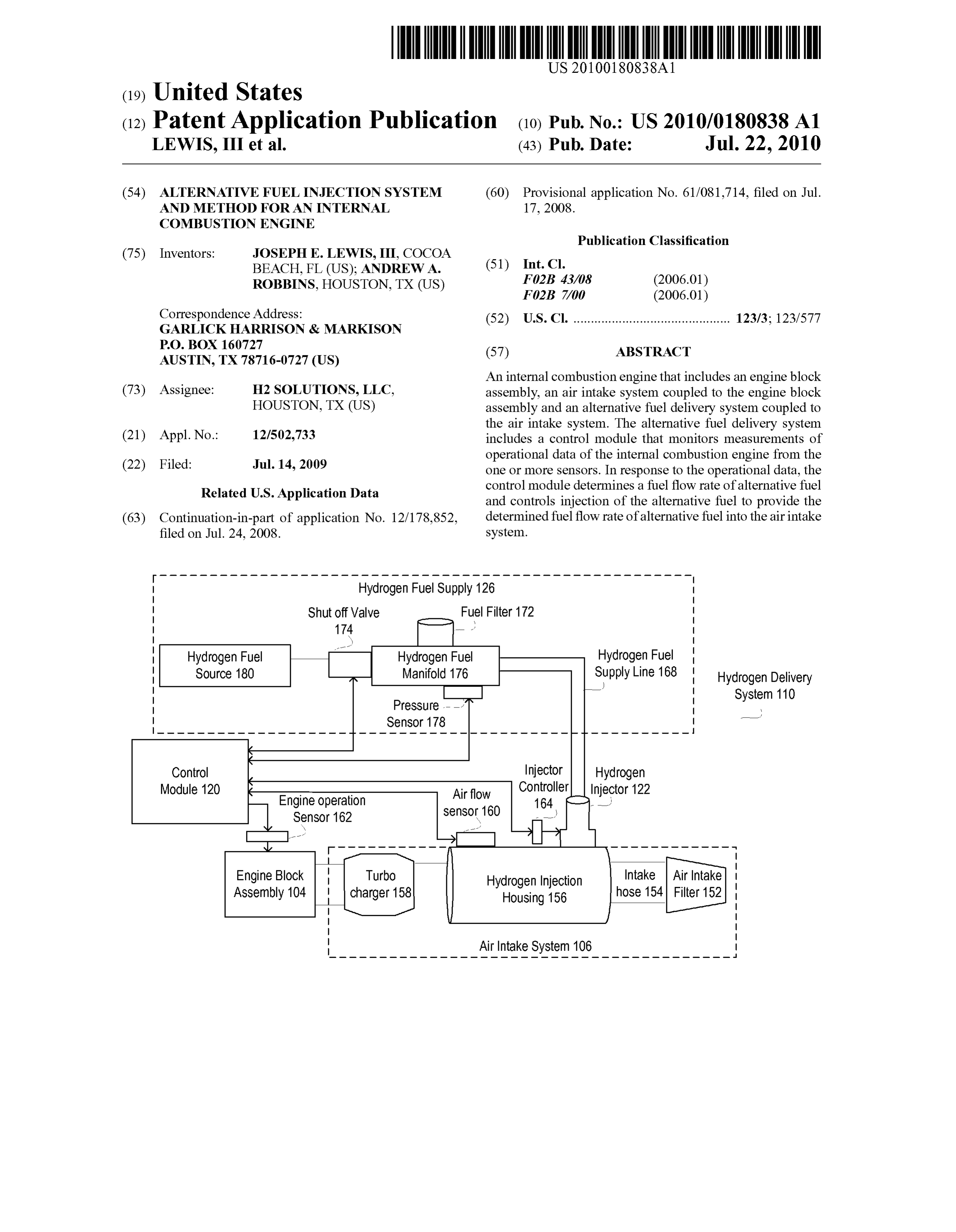
Hydrogen Fuel Supply 126
Hydrogen Fuel Hydrogen Fuel Hydrogen Fuel
SOUrce 180 Manifold 176 Supply Line 168 Hydrogen Delivery
Control Injector Hydrogen
Module 120 Airflow Controller Injector 122 sensor 160
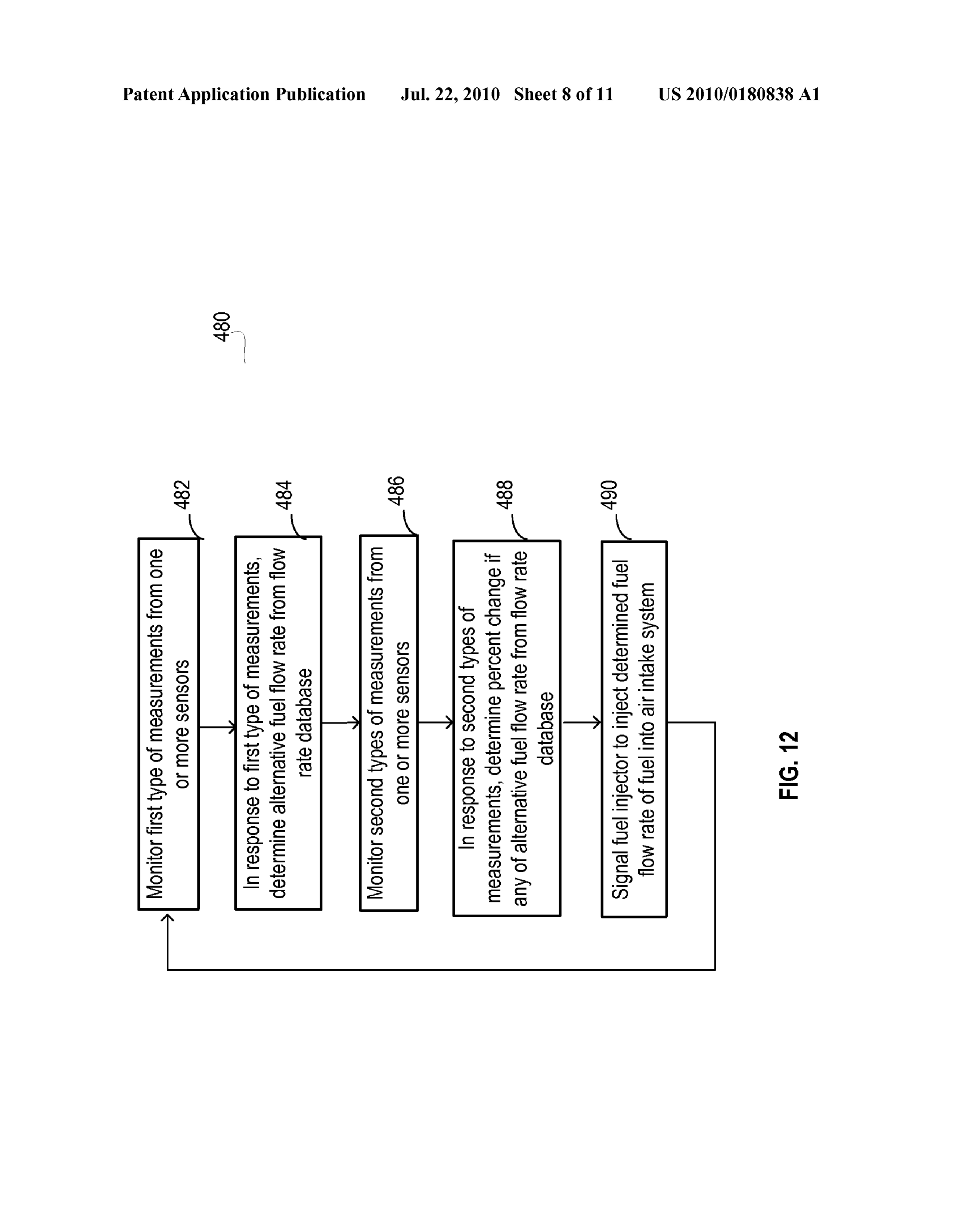
Engine Block Turbo Hydrogen injection
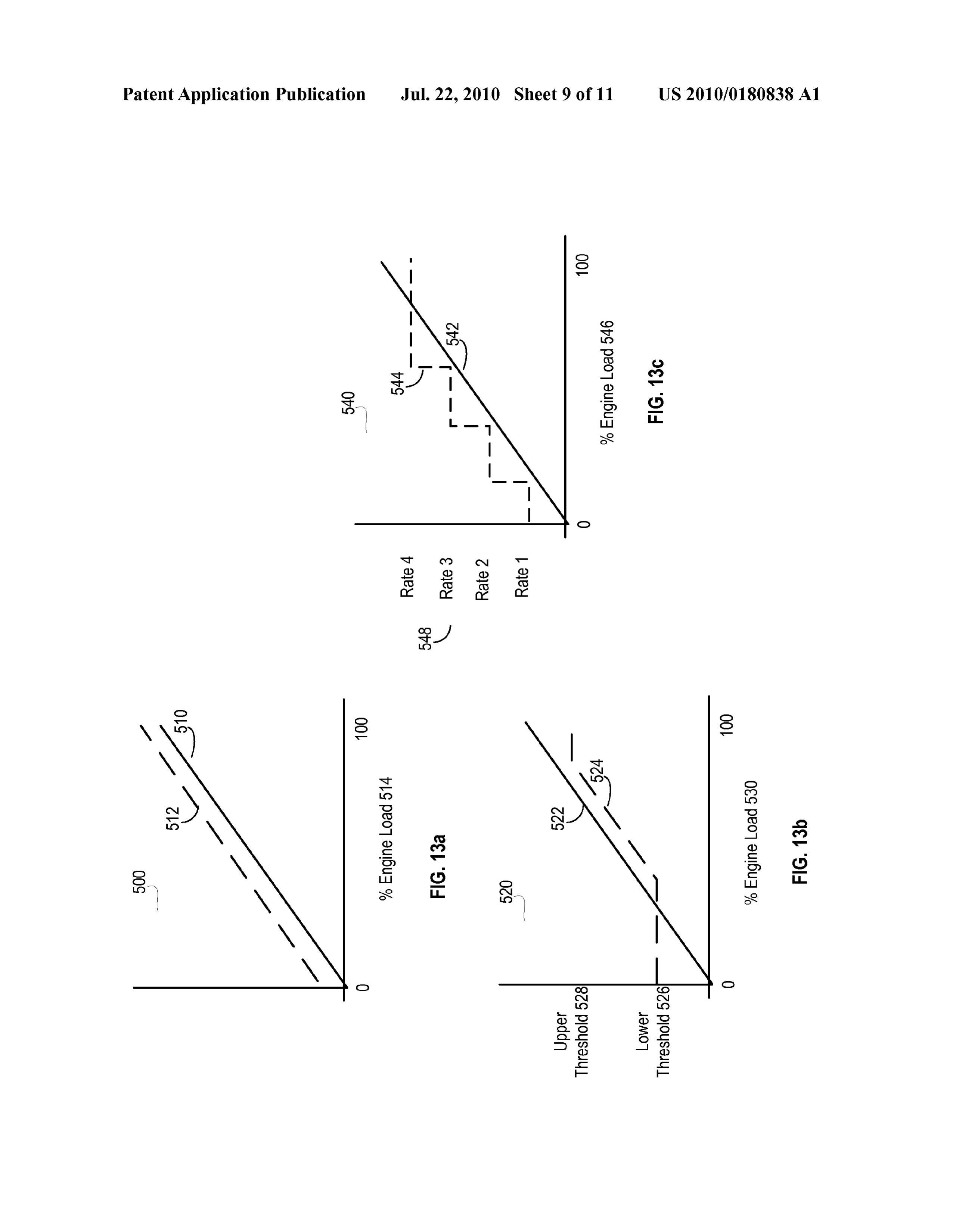
Assembly 104 charger 158 Housing 156
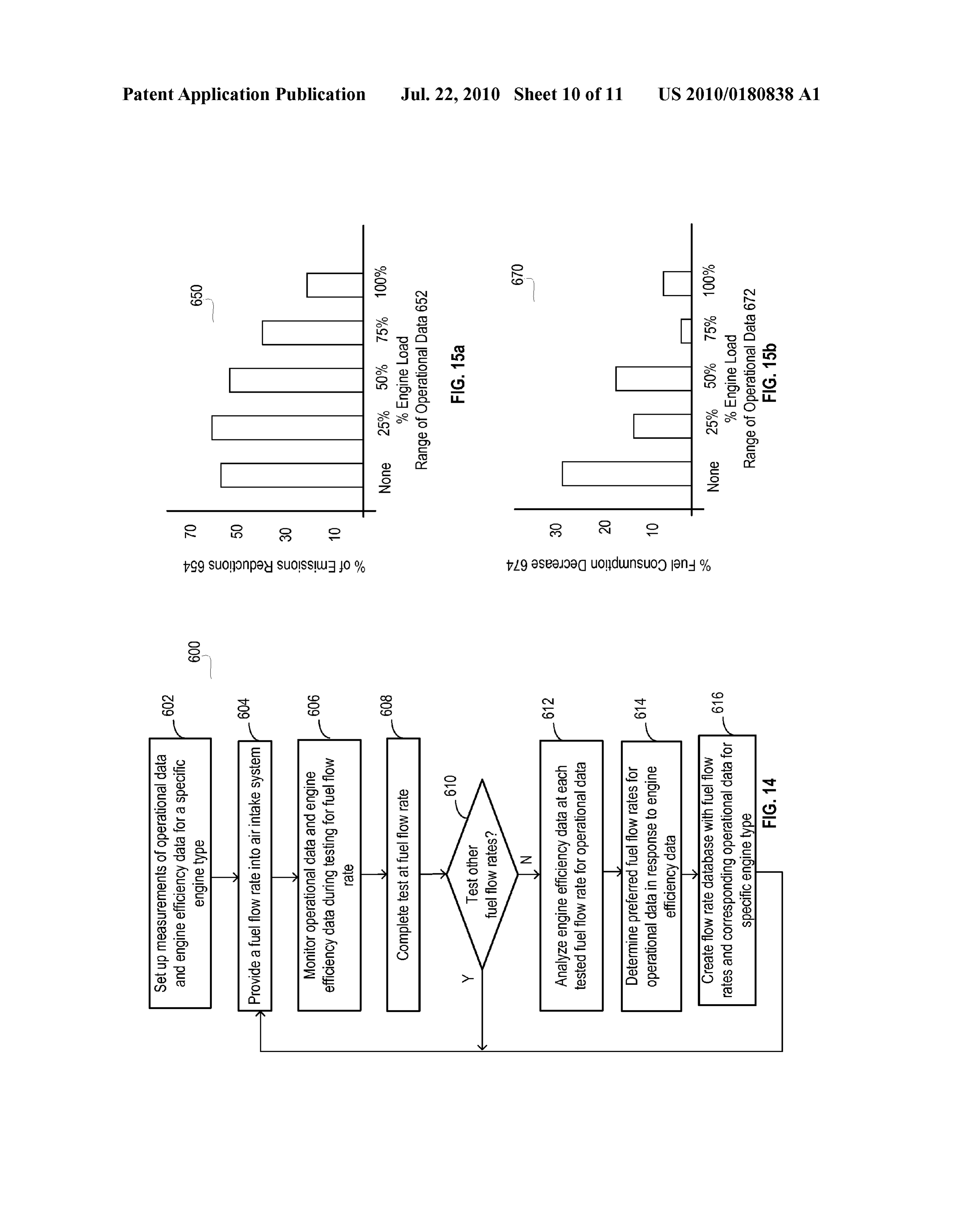
Page 2
Drawing sheet — no readable text.
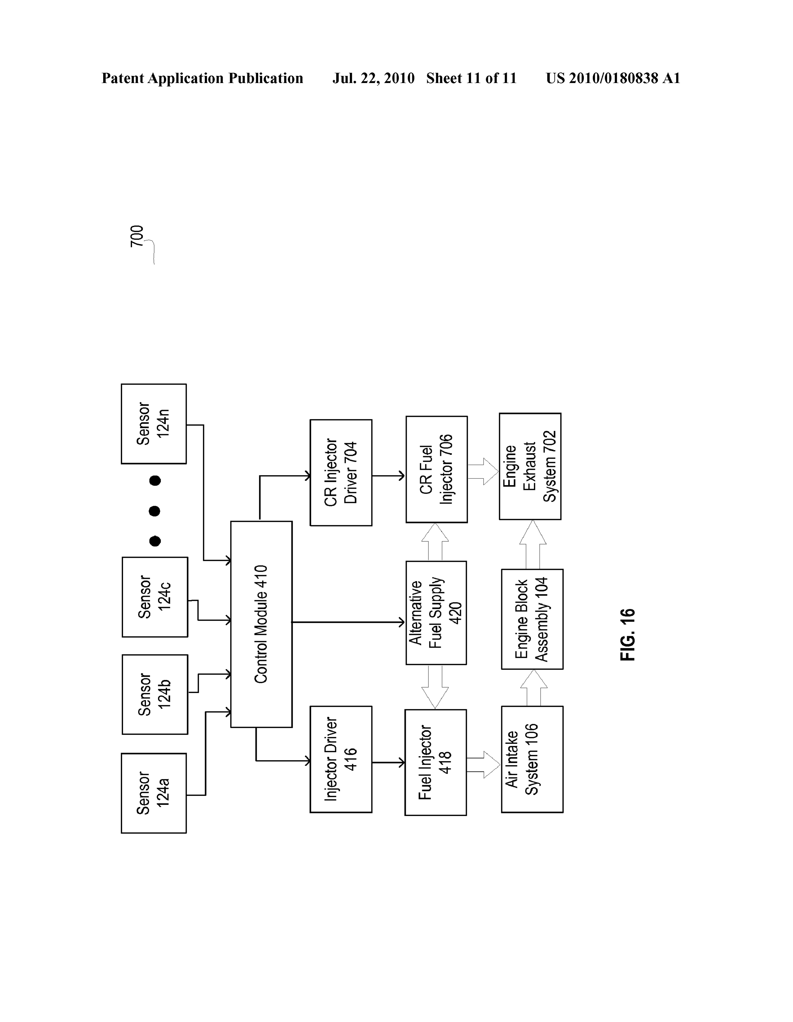
Page 3
Drawing sheet — no readable text.
Page 4
Drawing sheet — no readable text.
Page 5
Drawing sheet — no readable text.
Page 6
Drawing sheet — no readable text.
Page 7
Drawing sheet — no readable text.
Page 8
Drawing sheet — no readable text.
Page 9
Drawing sheet — no readable text.
Page 10
Drawing sheet — no readable text.
Page 11
Drawing sheet — no readable text.
Page 12
Drawing sheet — no readable text.
Page 13
US 2010/0180838 A1 Jul. 22, 2010
ALTERNATIVE FUEL INUECTION SYSTEM present invention will become apparent from the following AND METHOD FOR AN INTERNAL detailed description of the invention made with reference to COMBUSTON ENGINE the accompanying drawings.
CROSS REFERENCE TO RELATED BRIEF DESCRIPTION OF THE DRAWINGS
APPLICATIONS
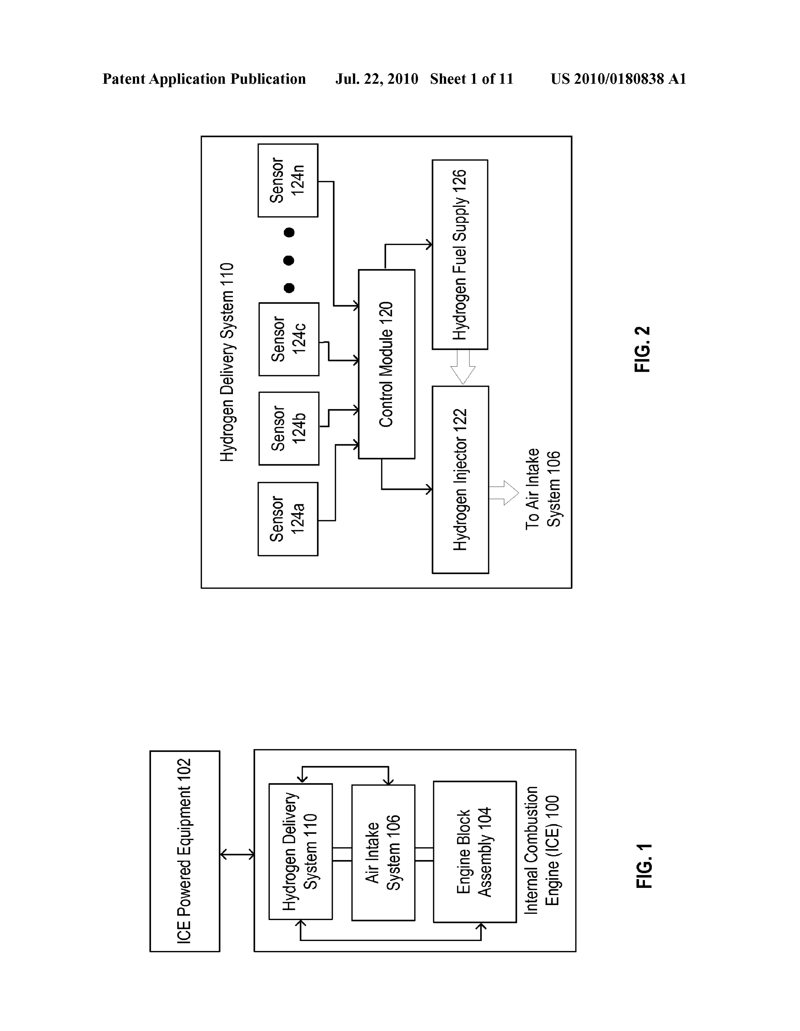
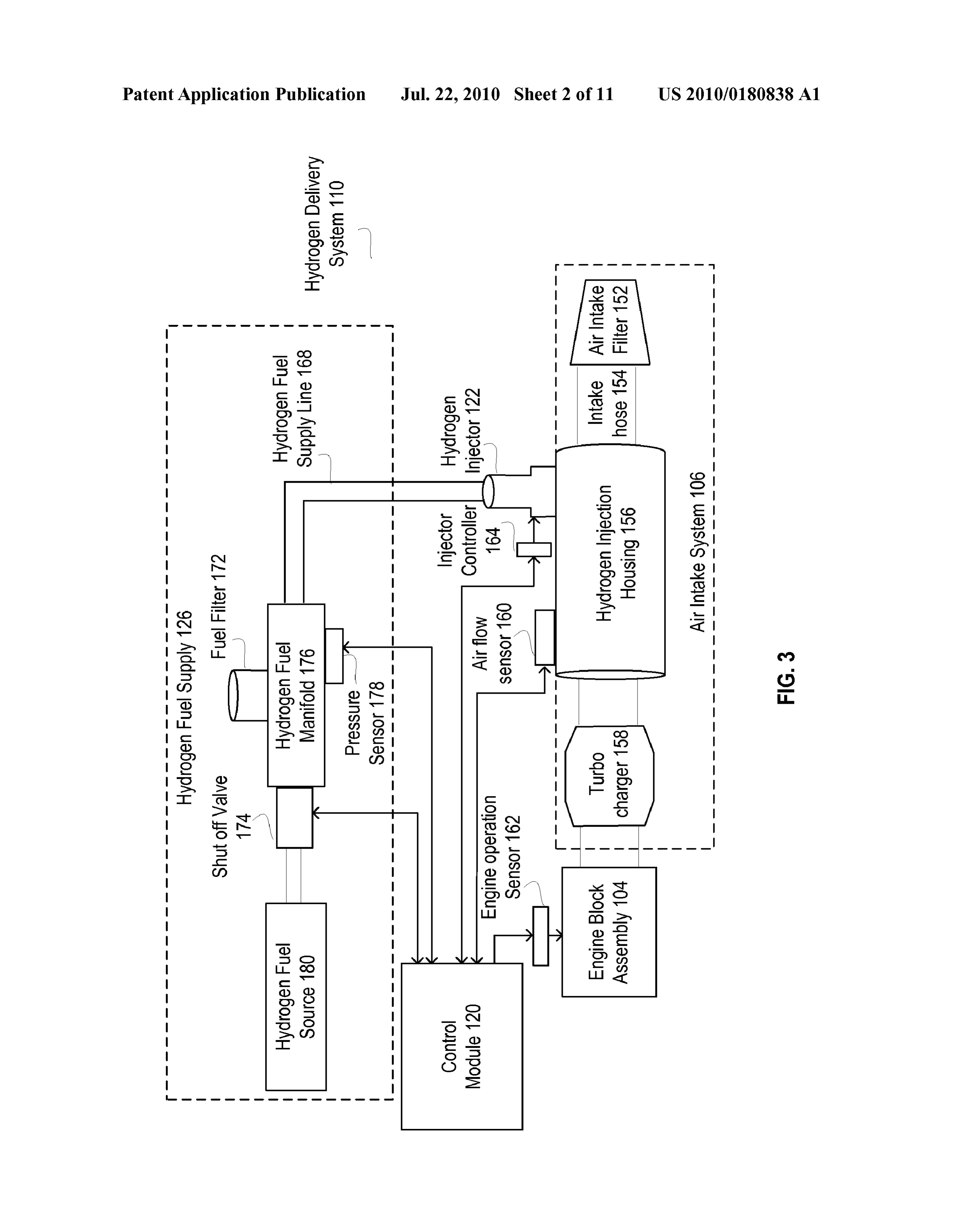
0009 FIG. 1 illustrates a schematic block diagram of an embodiment of an internal combustion engine with a hydro 0001. This US patent application claims priority as a con gen delivery system in accordance with the present invention. tinuation-in-part application under 35 USC S 120 to a prior 0010 FIG. 2 illustrates a schematic block diagram of an filed utility patent application entitled, “Hydrogen Delivery embodiment of a hydrogen delivery system in accordance System and Method for an Internal Combustion Engine.” with the present invention.
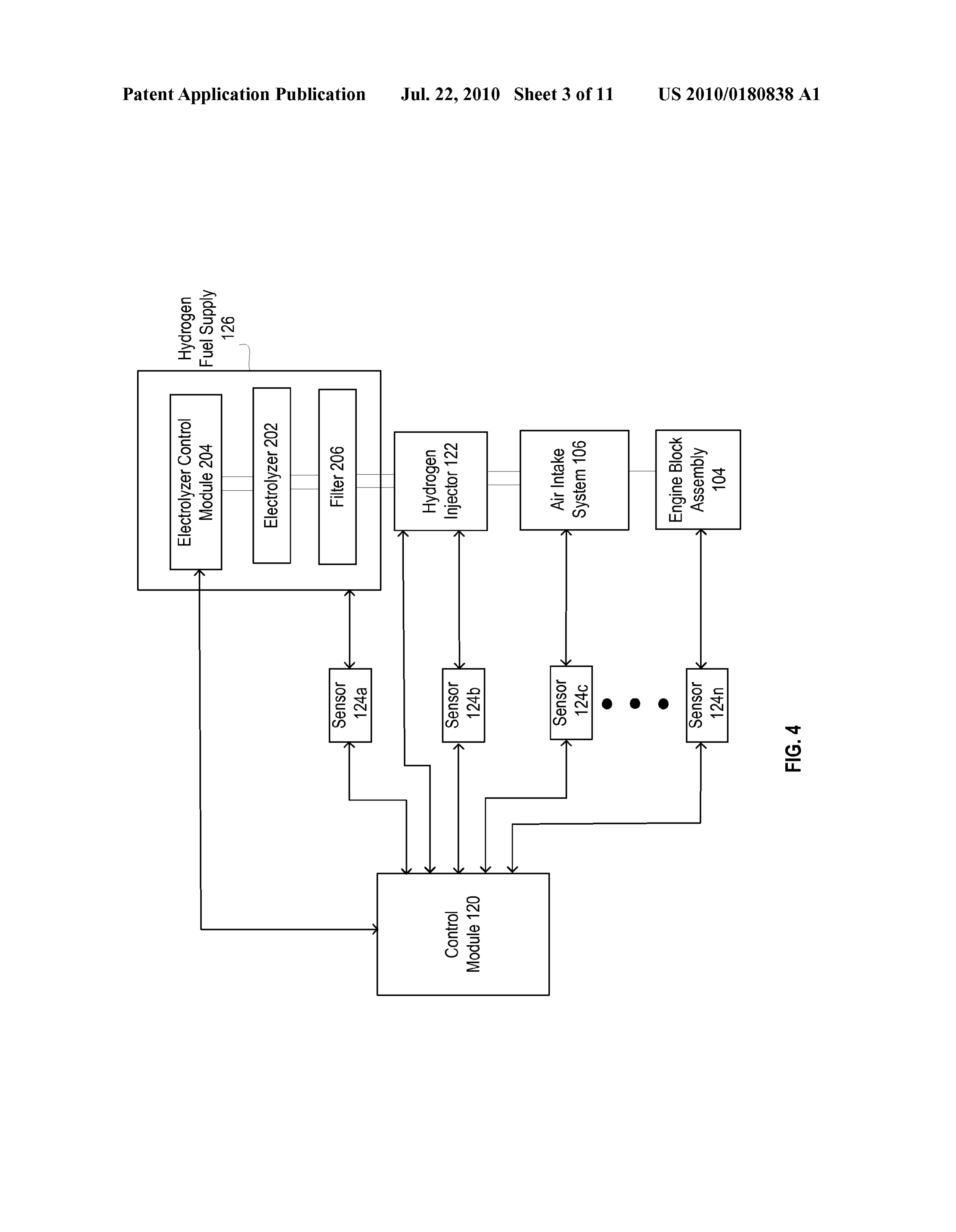
having a filing date of Jul. 24, 2008 and an application Ser. 0011 FIG. 3 illustrates a schematic block diagram of No. 12/178,852, which claims priority under 35 U.S.C. S 119 another embodiment of the hydrogen delivery system in to a provisionally filed patent application entitled, “Hydrogen accordance with the present invention. Delivery System and Method for an Internal Combustion 0012 FIG. 4 illustrates a schematic block diagram of Engine.” having a provisional filing date of Jul. 17, 2008, and another embodiment of the hydrogen delivery system in a provisional application Ser. No. 61/081,714, both of which accordance with the present invention. are hereby incorporated herein by reference. 0013 FIG. 5 illustrates a logic flow diagram of an embodi ment of a method for hydrogen delivery in accordance with
BACKGROUND OF THE INVENTION the present invention.
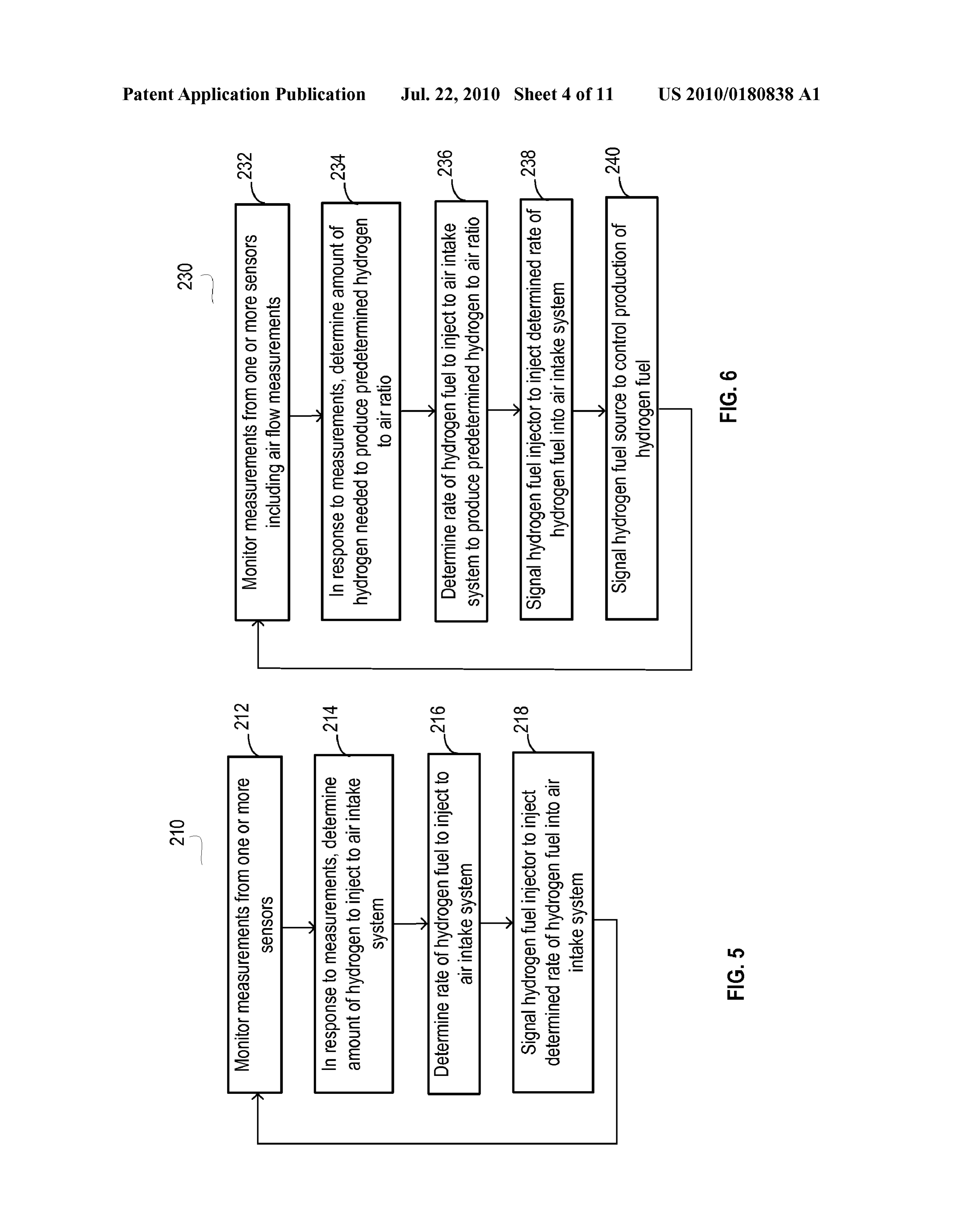
0014 FIG. 6 illustrates a logic flow diagram of another 0002 1. Field of the Invention embodiment of a method for hydrogen delivery in accordance 0003. The application generally relates to internal com with the present invention.
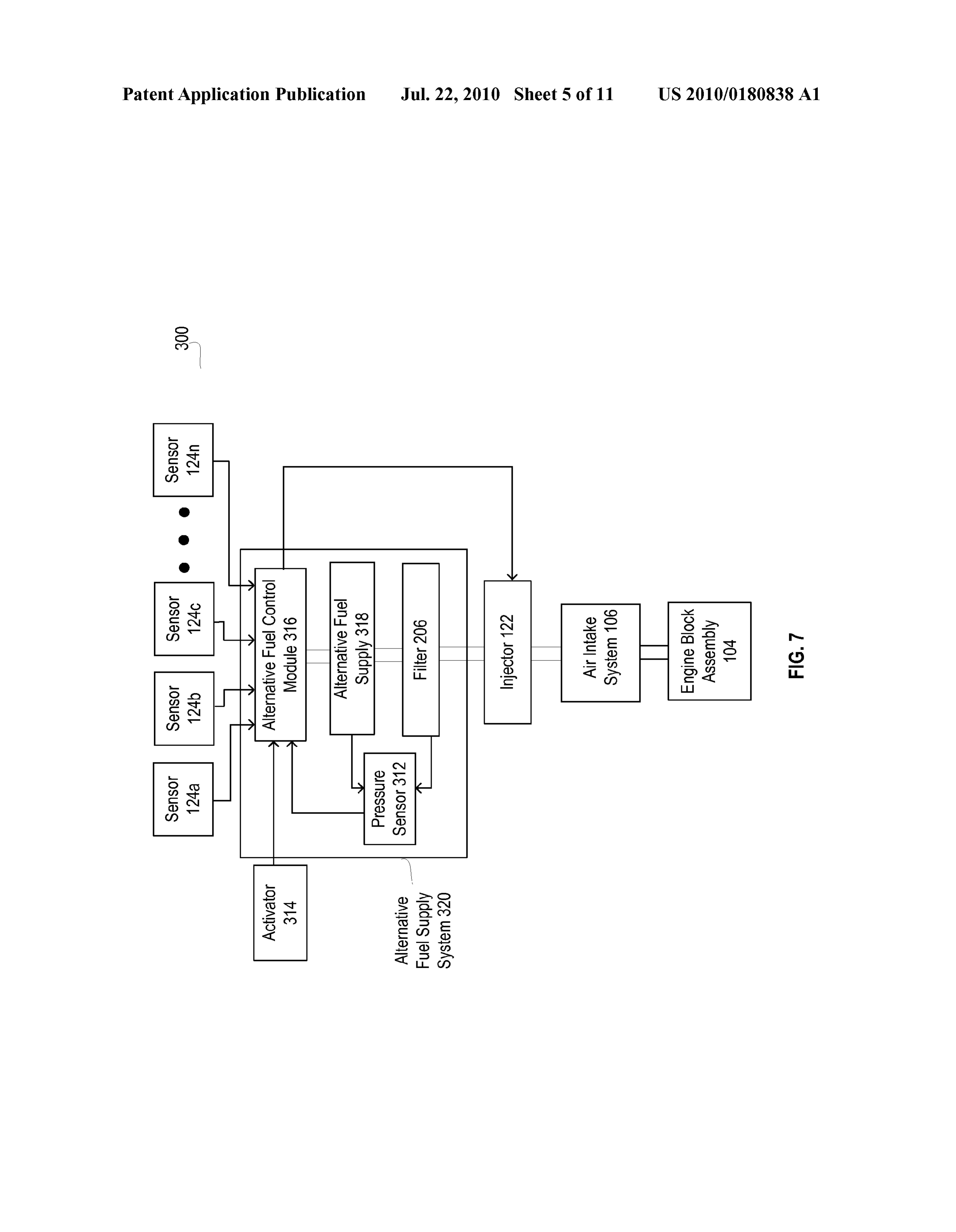
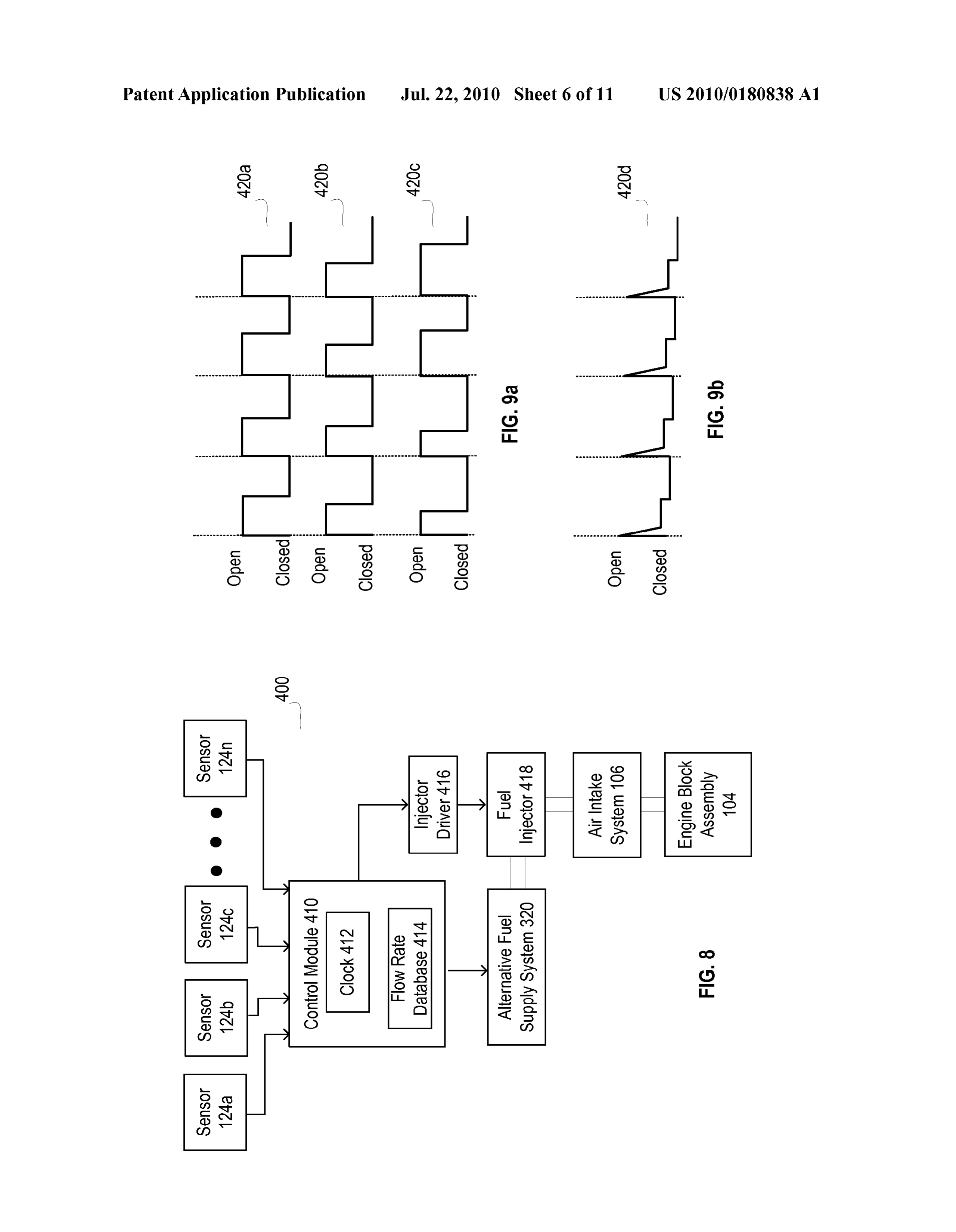
bustion engines, and more particularly to an improved system 0015 FIG. 7 illustrates a schematic block diagram of an and method for alternative fuel delivery to an internal com embodiment of an alternative fuel delivery system in accor bustion engine. dance with the present invention. 0016 FIG. 8 illustrates a schematic block diagram of 0004 2. Description of the Related Art another embodiment of the alternative fuel delivery system in 0005. In an internal combustion engine, fuel and an oxi accordance with the present invention. dizer are combined in a cylinder or combustion chamber. 0017 FIGS. 9a and 9b illustrate a schematic diagram of an Typically engines use either a spark method or a compression embodiment of operation of a control module in the alterna method to achieve ignition. Through ignition, an exothermic tive fuel delivery system in accordance with the present chemical reaction or combustion occurs in the cylinder in invention.
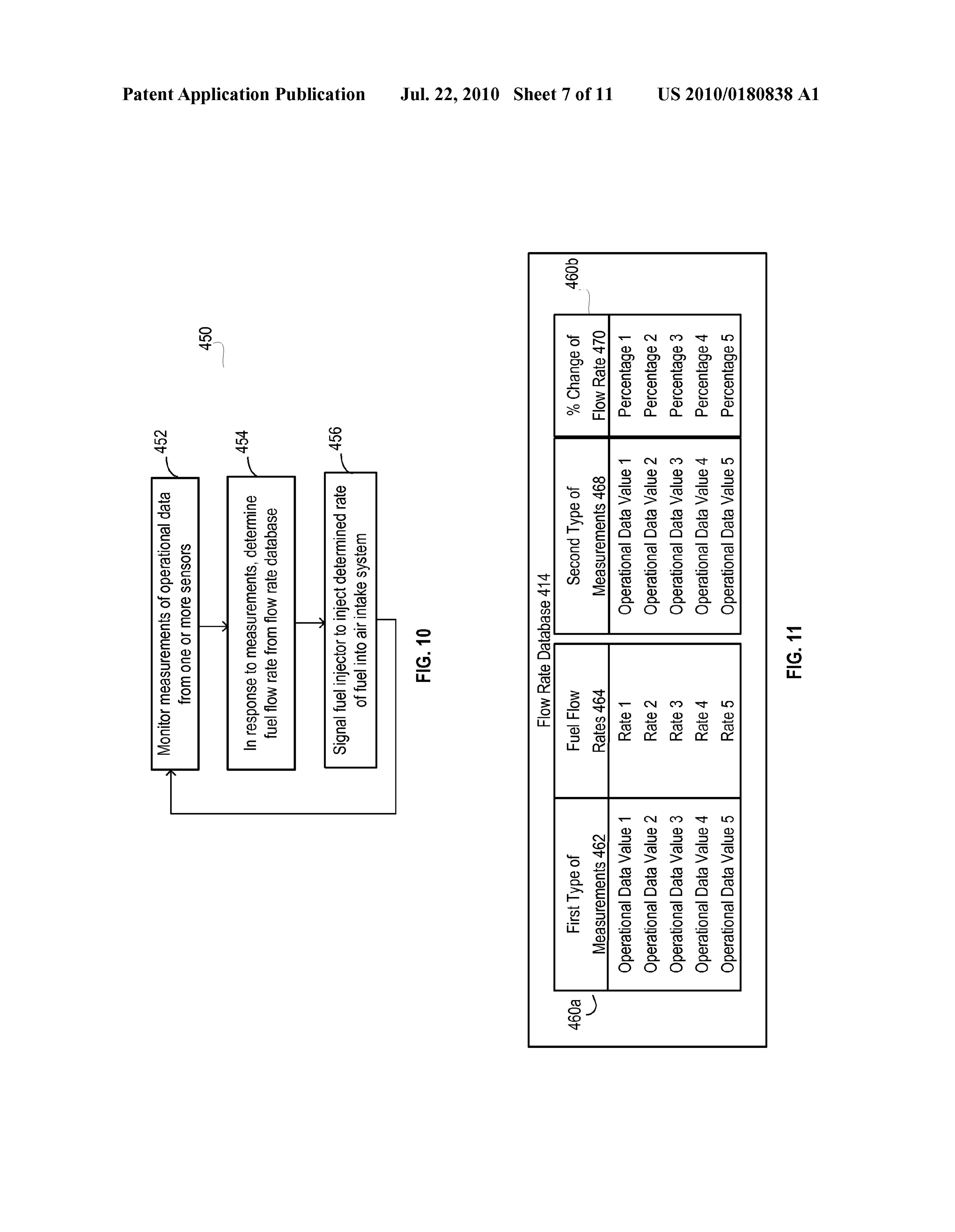
which hot gases expand to move a part of the engine, such as 0018 FIG. 10 illustrates a logic flow diagram of an a piston or a rotor. Typically, the oxidizer for an internal embodiment of a method for alternative fuel delivery in combustion engine is air, and the fuel is a hydrocarbon based accordance with the present invention. fuel derived from petroleum or biomass. Such as diesel, gaso 0019 FIG. 11 illustrates a schematic block diagram of an line, petroleum gas, ethanol, biodiesel or propane or combi embodiment of a fuel flow rate database. nation thereof. 0020 FIG. 12 illustrates a logic flow diagram of an 0006. The increasing cost of petroleum fuels for internal embodiment of a method for alternative fuel delivery in combustion engines has created a demand for greater fuel accordance with the present invention. efficiency. One approach that has been developed is the addi 0021 FIGS. 13a, 13b and 13c illustrate graph diagrams of tion of hydrogen to the combustion process. It has been found embodiments of example fuel flow rates in a fuel flow rate that when hydrogen is mixed with a hydrocarbon based fuel in database.
the cylinder of an internal combustion engine, there is an 0022 FIG. 14 is a logic flow diagram of an embodiment of improved combustion efficiency and a reduction of noxious a method for determining fuel flow rates in response to engine emissions. In current systems, hydrogen is added to the air efficiency data.
that is introduced into the cylinder. Typically, the same vol (0023 FIGS. 15a and 15b illustrate bar graphs of an ume of hydrogen is added to the air regardless of airflow rate, embodiment of an example analysis performed to determine engine load or engine revolution per minute (RPM) consid fuel flow rates.
erations.
0024 FIG. 16 illustrates a schematic block diagram of an 0007 As such, there is a need for an improved system and embodiment of a method for alternative fuel delivery in method for hydrogen delivery to an internal combustion accordance with the present invention. engine.
DETAILED DESCRIPTION OF THE INVENTION
BRIEF SUMMARY OF THE INVENTION
0025. While the invention will be described in connection 0008. The present invention is directed to a system and with the preferred embodiments, it will be understood that it method for hydrogen delivery to an internal combustion is not intended to limit the invention to those embodiments. engine as described in the following Brief Description of the On the contrary, it is intended to cover all alternatives, modi Drawings, the Detailed Description of Embodiments of the fications, and equivalents thereof. Similar parts will be Invention and The Claims. The features and advantages of the labeled with the same numbers in the figures though a person
Page 14
US 2010/0180838 A1 Jul. 22, 2010
of skill in the art would appreciate that various alternatives, corresponding operational instructions may be embedded modifications and equivalents may be substituted for Such within, or external to, the circuitry comprising the State similar parts. machine, analog circuitry, digital circuitry, and/or logic cir 0026. As described above, the current systems for hydro cuitry. Further note that, the memory element stores, and the gen delivery introduce a constant Volume of hydrogen to the control module executes, hard coded and/or operational air intake system of an internal combustion engine regardless instructions corresponding to at least Some of the steps and/or of airflow rate, engine load or engine revolutions per minute functions illustrated in FIGS. 1-15 herein. (RPM) considerations. However, the airflow rate through the 0030 The sensors 124a-n measure operational data of the air intake system varies. By only injecting an unvarying Vol internal combustion engine 100. The sensors 124a-n may be ume of hydrogen, different hydrogen to air ratios are pro coupled to the engine block assembly 104, the air intake duced in the air intake system and in the cylinders during the system 106, hydrogen delivery system 110. The sensors combustion process. The differing values of hydrogen to air 124a-n include, inter alia, thermometers, throttle body posi ratio in the cylinders creates inefficiencies in the combustion tion sensors, revolutions per minute (RPM) sensor, pressure process. As such, there is a need for an improved system and sensors, volume flow sensor, or mass air flow (MAF) sensor, method for hydrogen delivery to an internal combustion Such as hot film or hot wire sensor, barometric pressure sen engine. An embodiment of the present invention monitors the sor, Cam Shaft Position Sensor, Crank Shaft Position Sensor, flow rate of air and adjusts the delivery of hydrogen to the air Exhaust Back Pressure sensor, engine oil temperature sensor, intake system of the internal combustion engine to optimize engine oil pressure sensor, exhaust back pressure regulator, the hydrogen to air ratio for the internal combustion engine. Fuel Delivery Control Signal, Glow Plug Relay, Hydrauli 0027 FIG. 1 is a schematic block diagram of an embodi cally Actuated Electronically controlled Unit Injector, Intake ment of an internal combustion engine with a hydrogen deliv Air Temperature. Injection Control Pressure, Injection Pres ery system in accordance with the present invention. FIG. 1 sure Regulator, Injector Driver Module, Injector Driver Mod illustrates an internal combustion engine (ICE) 100 coupled ule Enable. Injection Control Pressure Regulator, Idle Vali to an ICE powered equipment 102. The ICE powered equip dation Switch, Manifold Absolute Pressure (MAP), Manifold ment 102 includes for example, vehicles, airplanes, marine, Air Temperature Sensor, Power train Control Module sensor, locomotives, generators, oil field equipment and other appli Speed Control Command Switch sensor, tachometer output cations. The ICE 100 includes an engine block assembly 104, sensor. Accelerator Position Sensor, Hall Effect Sensor, Mag an air intake system 106 and a hydrogen delivery system 110 netic Pick Up (Magnetic Speed Sensor), Thermister, Alterna coupled to the air intake system 106. The engine blockassem tor Charge Output Signal, Vehicle Speed Sensor, Vacuum bly 104 includes the engine block, cylinders and pistons or Sensor, Alternator Output Signal sensor, Glow Plug Control rotors. The air intake system 106 deliversair to the cylinders sensor, Vehicle Power Supply sensor, vehicle Reference Volt in the engine block assembly 104. The air intake system 106 age sensor, and Wastegate Control sensor. may include a turbocharger or Supercharger and air filter. 0031. The hydrogen injector 122 may be a high pressure 0028. In operation, the hydrogen delivery system 110 injector or a low pressure injector depending on the pressure monitors the air flow rate through the air intake system 106 of the hydrogen fuel and the volume of hydrogen needed to be and controls the injection of hydrogen into the air intake injected into the air intake system 106. system 106 to produce a desired, predetermined hydrogen to 0032. In operation, one or more of the sensors 124a-n air ratio. In an embodiment, the hydrogen may be injected provide measurements of operational data of the internal after the turbocharger in the air intake system 106. In another combustion engine 110. The measurements of operational embodiment, the hydrogen may be injected before the turbo data may include, interalia, measurements of mass air flow, charger Such that it pressurizes the air and hydrogen together. Volume air flow, vacuum, temperature, engine RPM, mani This helps to mix the air for a more homogenous blend. fold absolute pressure, throttle position, engine load, crank 0029 FIG. 2 is a schematic block diagram of an embodi shaft position or other operational data. The control module ment of the hydrogen delivery system 110 in accordance with 120 monitors the operational data from the sensors 124a-n the present invention. The hydrogen delivery system 110 and determines a desired amount, either Volume or mass, of includes a control module 120, a hydrogen injector 122, one hydrogen fuel to be injected into the air intake system 106 in or more sensors 124a-n and a hydrogen fuel Supply 126. The response to the measurements of operational data. As the control module 120 is a processing device including a micro operational data changes, for example due to increase or processor, micro-controller, digital signal processor, micro decrease in the engine RPM, air flow, or other changes, the computer, central processing unit, field programmable gate control module 120 continually updates the desired amount array, programmable logic device, state machine, logic cir of hydrogen fuel to be injected into the air intake system 106. cuitry, analog circuitry, digital circuitry, or any device that The control module 120 then controls the hydrogen injector manipulates signals (analog and/or digital) based on hard 122 to provide a flow rate of hydrogen fuel to the air intake coding of the circuitry or operational instructions. The pro system 106 to deliver the determined amount of hydrogen cessing device may have an associated memory element, fuel.
which may be a single memory device, a plurality of memory 0033 For example, in an embodiment, the control module devices, or embedded circuitry of the control module. Such a 120 receives operational data of the engine RPM from one or memory device may be a read-only memory, random access more of the sensors 124a-n. Based on the engine RPM data, memory, Volatile memory, non-volatile memory, static the control module 120 determines the desired amount, Vol memory, dynamic memory, flash memory, cache memory, ume or mass of hydrogen fuel to be injected into the air intake and/or any device that stores digital information. Note that system 106. The control module 120 then controls the hydro when the control module implements one or more of its gen injector 122 to provide a flow rate of hydrogen fuel to the functions via a state machine, analog circuitry, digital cir air intake system 106 to deliver the desired amount, volume or cuitry, and/or logic circuitry, the memory element storing the mass of hydrogen. In another embodiment, the control mod
Page 15
US 2010/0180838 A1 Jul. 22, 2010
ule 120 receives operational data of the throttle position from gen injection housing 156 and a turbocharger 158. An airflow one or more of the sensors 124a-in. Based on the throttle sensor 160 is coupled to the hydrogen injection housing 156 position data, the control module 120 determines the desired to provide measurements of airflow in the hydrogen injection volume or mass of hydrogen fuel to be injected into the air housing 156. In an embodiment, the air flow sensor 160 is a intake system 106. In another embodiment, the control mod mass air flow sensor, Such as a hot wire or hot film anemom ule 120 receives operational data of the airflow from the mass eter. In an embodiment, an engine operation sensor 162 is air flow sensor through the air intake system 106. Based on coupled to the engine block assembly or component of the the mass air flow data, the control module determines the internal combustion engine 100. The engine operation sensor desired volume or mass of hydrogen fuel to be injected into 162 is operable to detect whether the engine is operational by the air intake system 106. detecting any RPM of the engine 100 or ignition or other 0034. In another embodiment, a sensor 124a-n provides means. The air flow sensor 160 and engine operation sensor operational data relating to the speed of a turbocharger rotor 162 each may comprise one of the sensors 124a-in described in the internal combustion engine 100. Based on the turbo in FIG.2. Other sensors 124a-n may also provide one or more charger rotor speed data, the control module 120 determines additional measurements to the control module 120 as the desired amount of hydrogen fuel to be injected into the air described with respect to FIG. 2.
intake system 106. In another embodiment, a sensor 124a-n 0038 Referring again to FIG.3, the hydrogen fuel injector provides operational data relating to amount of fuel. Such as 122 is coupled to the hydrogen injection housing 156 in the air diesel or gasoline or other type of fuel, injected into a com intake system 160. The hydrogen injection housing 156 may bustion chamber of the engine block assembly 104. The con be mounted to an existing internal combustion engine 104 or trol module 120 may then correlate the fuel operational data be incorporated into manufacture of a new internal combus to RPM of the engine block assembly 104 and determine the tion engine 104. The hydrogen fuel injector 122 and air flow desired amount of hydrogen fuel to be injected into the air sensor 160 are mounted before the turbocharger 158. In intake system 106. In another embodiment, a sensor 124a-n another embodiment, the hydrogen fuel injector 122 and air provides operational data relating to intake vacuum on a flow sensor 160 may be mounted after the turbocharger 158. turbocharger or Supercharger in an internal combustion An injector controller 164 is coupled to the hydrogen fuel engine 100. Based on the operational data of the intake injector 122 and the control module 120. Depending on the vacuum, the control module 120 may determine the desired implementation of the hydrogen fuel Supply 126, the injector amount of hydrogen fuel to be injected into the air intake controller 164 may be incorporated as a component of the system 106. In an embodiment with an internal combustion hydrogen injector 122 or as a separate component. The injec engine 100 having a set operational RPM, such as a generator tor controller 164 is operable to control the opening and with a set RPM during operation, the control module 120 may closing of the hydrogen injector 122 in response to control determine the desired amount of hydrogen fuel to be injected signals from the control module 120. into the air intake system 106 based on one or more measure 0039. The hydrogen fuel supply 126 is coupled to the ments from the sensors 124a-n. hydrogen injector 122. The hydrogen fuel supply 126 0035. In another embodiment, the control module 120 includes a hydrogen fuel supply line 168, a fuel filter 172, a receives one or more measurements of operational data com shut off valve 174, a hydrogen fuel manifold 176, a pressure prising of inter alia, mass air flow (MAF), volume air flow, sensor 178 and a hydrogen fuel source 180. The pressure intake vacuum on a turbocharger, turbocharger rotor speed, sensor 178 is coupled to the hydrogen fuel manifold 176 or amount of fuel injected into the engine block assembly 104, shut off valve or other component of the hydrogen fuel supply temperature, engine RPM, manifold absolute pressure 126 to measure the pressure of the hydrogen fuel. The pres (MAP), throttle position, engine load and crankshaft position sure sensor 178 may comprise one of the sensors 124a-n and determines an amount of hydrogen fuel to be injected into described in FIG. 2. The shut off valve 174 is a solenoid valve the air intake system 106 based on one or more of the mea or other safety valve. The fuel filter 172 is operable to filter Surements of operational data. contaminates and moisture from the hydrogen fuel. 0036. In an embodiment, the hydrogen fuel supply 126 is 0040. In operation, the control module 120 receives pres a tank or other type of container with high pressure hydrogen sure measurements from the pressure sensor 178 and deter fuel. The hydrogen fuel may include hydrogen (H2), oxygen, mines whether the pressure is within operating conditions. methane, propane, nitrogen, Sulphur dioxide (SOX) and any When the pressure exceeds or falls below operating condi combination of these gases or other hydrocarbon based gases. tions, the control module 120 signals the shut off valve 174 to In another embodiment, the hydrogen fuel source 126 is a close to protect the system integrity. In addition, the control hydrogen generator, such as an electrolyzer. In this embodi module 120 receives data from the engine operation sensor ment, the hydrogen fuel includes an electrolyZergas consist 162 and determines whether the internal combustion engine ing of hydrogen 2H and oxygen O. The control module 120 100 is operational. In response to the determination that the monitors the hydrogen fuel Supply 126 to determine a pres engine 100 is operational, the control module 120 signals the Sure of the hydrogen fuel. Depending on the pressure of the shut off valve 174 to open or in response to a determination hydrogen fuel, the type of hydrogen fuel, the control module that the engine 100 is not operational, the control module 120 120 controls the opening and closing of the hydrogen injector signals the shut off valve 174 to close. When the pressure is 122. The hydrogen injector 122 injects the desired flow rate of within operating conditions and the engine is operational, the hydrogen fuel into the air intake system 106 in response to control module 120 determines an air flow rate and then control signals from the control module 120. determines a flow rate of the hydrogen fuel into the air intake 0037 FIG. 3 illustrates a schematic block diagram of an system 106 to produce a predetermined hydrogen to air ratio embodiment of the hydrogen delivery system 110 in accor in the air intake system 106.
dance with the present invention. The air intake system 106 0041. In an embodiment, the control module 120 may includes an air intake filter 152, an intake hose 154, a hydro determine a volume air flow rate or a mass air flow rate. The
Page 16
US 2010/0180838 A1 Jul. 22, 2010
control module 120 receives air flow measurements from the means. The electrolyzer control module 204 is a processing airflow sensor 160. The volume airflow rate is determined in device including a microprocessor, micro-controller, digital response to the airflow measurements and airflow area of the signal processor, microcomputer, central processing unit, hydrogen injection housing 156. The control module 120 may field programmable gate array, programmable logic device, also receive air pressure measurements and air temperature state machine, logic circuitry, analog circuitry, digital cir measurements. From these measurements, the control mod cuitry, or any device that manipulates signals (analog and/or ule 120 may determine the approximate density of the air to digital) based on hard coding of the circuitry or operational determine mass airflow rate from the volume airflow rate. In instructions. The processing device may have an associated another embodiment, the control module 120 may determine memory element, which may be a single memory device, a the mass airflow rate from the airflow sensor 160 when the air plurality of memory devices, or embedded circuitry of the flow sensor is a mass air flow sensor Such as a hot film or hot control module. Such a memory device may be a read-only wire anemometer. memory, random access memory, Volatile memory, non-vola 0042. The control module 120 then determines the flow tile memory, static memory, dynamic memory, flash memory, rate of the hydrogen fuel in response to the air flow rate. The cache memory, and/or any device that stores digital informa control module 120 determines the hydrogen flow rate needed tion. Note that when the control module implements one or to provide a predetermined hydrogen to air ratio in the air more of its functions via a state machine, analog circuitry, intake system 106 or engine block assembly 104. The hydro digital circuitry, and/or logic circuitry, the memory element gen flow rate determined also depends on the percentage of storing the corresponding operational instructions may be hydrogen in the hydrogen fuel. For example, when the hydro embedded within, or external to, the circuitry comprising the gen fuel source 180 is a tank with pressurized hydrogen, the state machine, analog circuitry, digital circuitry, and/or logic hydrogen fuel will have a high concentration of hydrogen. circuitry. Further note that, the memory element stores, and However, when the hydrogen fuel source is an electrolyzer, the control module executes, hard coded and/or operational the concentration of hydrogen in the hydrogen fuel is lower. instructions corresponding to at least Some of the steps and/or functions illustrated in FIGS. 1-16 herein.
The control module 120 is programmed with a concentration for the type of hydrogen fuel. Variable hydrogen concentra 0044. In operation, the control module 120 monitors, inter tions in the hydrogen fuel are taken into consideration by the alia, the flow rate, pressure or volume of the hydrogen fuel control module 120 when determining the fuel flow rate of from the hydrogen fuel supply 126. To adjust the hydrogen hydrogen fuel needed to inject into the air intake system 106. fuel generated, the control module 120 transmits an electro To produce predetermined hydrogen to air ratio in the air lyzer control signal to the electrolyzer control module 204. In intake system 106, the control module 120 determines the response to the electrolyzer control signal, the electrolyzer flow rate of the hydrogen fuel into the hydrogen injection control module 204 starts or terminates production of hydro housing 156 in response to airflow, engine load, RPMorother gen fuel by the electrolyzer 202. The control module 120 operational data and the concentration of hydrogen in the receives data from the engine operation sensor 162 and deter hydrogen fuel. The control module 120 then controls injec mines whether the internal combustion engine 100 is opera tion of the hydrogen fuel into the air intake system to produce tional. In response to the determination that the engine 100 is the predetermined hydrogen to air ratio. As the engine load operational, the control module 120 signals the electrolyzer and RPM increases or decreases and the air flow rate control module 204 to start production. In response to a increases or decreases, the control module 120 continues to determination that the engine 100 is not operational, the con monitor the operation data and adjust the hydrogen flow rate trol module 120 signals the electrolyzer control module 204 into the air intake system to produce a predetermined hydro to terminate production.
gen to air ratio. 0045. In another embodiment, the electrolyzer control 0043 FIG. 4 is a schematic block diagram of another module 204 regulates the voltage or current applied to the embodiment of the hydrogen delivery system 110 in accor electrolyzer 202. The control module 120 canthus control the dance with the present invention. In this embodiment, the rate of production of hydrogen fuel in response to the flow rate hydrogen fuel supply 126 includes an electrolyzer 202, elec needed at the hydrogen injector 122. trolyzer control module 204 and filter 206. The electrolyzer 0046 FIG. 5 is a logic flow diagram of a method 210 for 202 generates hydrogen and oxygen by a process of electroly hydrogen delivery to an air intake system 106 of an internal sis that separates hydrogen from water. The electrolyzer 202 combustion engine 100 in accordance with the present inven includes one or more electrodes in a water and electrolyte tion. In step 212, one or more measurements from one or more mixture. An electric current flows through the water and sensors are monitored on a continuous basis as the operating electrolyte mixture and oxygen (O) and hydrogen gas (H) conditions of the internal combustion engine change. For are generated. The electrolyzer control module 204 controls example, the measurements of operational data may include, the electrolyzer 202 and is operable to regulate the fuel pro inter alia, measurements of mass air flow, Volume air flow, duction of the electrolyzer 202. By regulating the current vacuum, temperature, engine RPM, manifold absolute pres flow, the Volume of oxygen (O2) and hydrogen gas (H2) Sure, throttle position, engine load and crank shaft position. generated by the electrolyzer may be adjusted. The generated 0047. In step 214, an amount of hydrogen, either volume oxygen (O) and hydrogen gas (H) comprise the hydrogen or mass of hydrogen, to inject into the air intake system 106 of fuel. The optional use of an oxygen separation filter 206 in the the internal combustion engine 100 is determined. The con electrolyzer fuel supply 126 reduces the oxygen in the hydro trol module 120 monitors the operational data from the sen gen fuel generated by the electrolyzer 202. In this embodi sors 124a-n and determines a desired amount, Volume or ment, the hydrogen fuel Supply 126 may also include check mass, of hydrogen to be injected into the air intake system 106 valves, expansion chambers, flashback prevention compo in response to the measurements of operational data. For nents, pressure Switches or other components. The electro example, in an embodiment, the control module 120 receives lyzer 202 may be powered by an alternator, battery or other operational data of the engine RPM. Based on the engine
Page 17
US 2010/0180838 A1 Jul. 22, 2010
RPM, the control module determines the desired amount, less than this ratio for other types of engines. In an embodi either Volume or mass, of hydrogen to be injected into the air ment, the hydrogen to air ratio will be less than 3%. intake system 106. The control module 120 then controls the 0051 Embodiments of the present invention are thus able hydrogen injector 122 to provide a flow rate of hydrogen fuel to adjust the delivery of the volume or flow rate of the hydro to the air intake system 106 to deliver the desired amount, gen fuel to maintain an approximately predetermined hydro either Volume or mass, of hydrogen. In another embodiment, gen to air ratio with varying engine RPM and load conditions the control module 120 receives operational data of the of the internal combustion engine. This adjustment helps to throttle position. Based on the throttle position, the control increase efficiency of the combustion process over the module determines the desired Volume or mass of hydrogen engine's operating range. With hydrogen gas blending, the to be injected into the air intake system 106. In another emissions of internal combustion engines are greatly reduced embodiment, the control module 120 receives operational across the operating range of the engine. data of the manifold absolute pressure (MAP). Based on the 0052. In an embodiment, the predetermined hydrogen to MAP, the control module determines an amount, volume or air ratio may not be a constant across the range of operational mass, of hydrogen to be injected into the air intake system data of the sensors. For example, the predetermined hydrogen 106. In another embodiment, the control module 120 receives to air ratio may be less at lower engine RPM and/or load and operational data of the mass air flow (MAF). Based on the greater for higher engine RPM and/or load. Thus, the control module 120 may vary the hydrogen to air ratio in response to
MAF, the control module determines an amount, volume or the operational data. The control module 120 then controls mass, of hydrogen to be injected into the air intake system the hydrogen injector 122 to provide a flow rate of hydrogen 106. fuel that provides the predetermined hydrogen to air ratio 0048. In step 216, a flow rate of hydrogen fuel is deter corresponding to the operational data of the internal combus mined in response to the amount of hydrogen needed to inject tion engine 100.
into the air intake system. The flow rate of hydrogen fuel 0053. In an embodiment, the hydrogen fuel includes varies in response to the determined Volume or mass of hydro hydrogen, oxygen and water vapor. In another embodiment, gen and the hydrogen concentration in the hydrogen fuel. In other alternative fuels are used such as methane, propane and step 218, the injection of hydrogen fuel into the air intake any combination of these gases or other hydrogen/carbon system is controlled to approximately meet the determined based gases. When other alternative fuels are incorporated flow rate for hydrogen fuel. into the hydrogen fuel, or used in place of the hydrogen in the 0049 FIG. 6 is a logic flow diagram of another embodi fuel, embodiments in FIGS. 1 through 16 may also be used to ment of a method 230 for hydrogen delivery in accordance deliver Such other alternative fuels to an engine block assem with the present invention. In step 232, measurements of the bly 104 in a similar manner. As described herein, the control air flow through the air intake system are monitored along module 120 determines a flow rate of the alternative fuel in with other measurements from sensors 124a-in needed to response to one or more measurements of operational data determine the volume airflow or mass airflow through the air from sensors 124a-n of the internal combustion engine 100. intake system 106. For example, the control module 120 may The control module 120 then controls an injector to provide also receive air pressure measurements and air temperature the flow rate of the alternative fuel into the air intake system measurements. From these measurements, the control mod or to the engine block assembly 104. ule 120 may determine the approximate density of the air to 0054 FIG. 7 is a schematic block diagram of an embodi determine mass airflow rate from the volume airflow rate. In ment of an alternative fuel delivery system 300. The alterna another embodiment, the control module 120 may determine tive fuel control module 316 controls the injection of alterna the mass airflow rate from the airflow sensor 160 when the air tive fuel into the air intake system 106 and the alternative fuel flow sensor is a mass air flow sensor Such as a hot film or hot supply system 320. In an embodiment, the alternative fuel wire anemometer. control module 316 is also operable to regulate production of 0050. In step 234, the amount of hydrogen to produce a alternative fuel by the alternative fuel supply 318. In an predetermined hydrogen to air ratio is determined in response embodiment, the alternative fuel control module 316 is to the air flow rate. In step 236, the flow rate of the hydrogen coupled to an activator 314. The activator 314 signals the fuel needed to provide the amount of hydrogen for the pre alternative fuel control module 316 to start or terminate pro determined hydrogen to air ratio in the air intake system 106 duction of alternative fuel and delivery of alternative fuel to is determined. The hydrogen flow rate depends on the per the air intake system 106. In an embodiment, the activator 314 centage of hydrogen in the hydrogen fuel and pressure of is an ignition switch for the internal combustion engine 100 or hydrogen fuel. In step 238, a signal controls the injection of other type of switch. The alternative fuel control module 316 the hydrogen fuel into the air intake system to produce the is also coupled to a pressure sensor 312. The pressure sensor predetermined hydrogen to air ratio. In step 240, in an 312 is coupled to the alternative fuel supply 318 or other embodiment with an electrolyzer, the generation of hydrogen component of the alternative fuel supply system 320 to mea fuel by the hydrogen fuel source is controlled in response to sure the pressure of the alternative fuel. In an embodiment, the determined flow rate for the hydrogen fuel. The process the alternative fuel supply 318 is an electrolyzer, plasma then continues back to step 232. As the operational conditions reformer, Steam reformer, catalytic reforming module or of the internal combustion engine 100 changes, the control other generator that is operable to produce hydrogen or other module 120 continues to monitor the air flow rate and adjust alternative fuels.
the hydrogen flow rate into the air intake system to produce a 0055. In an embodiment, the alternative fuel control mod predetermined hydrogen to air ratio. The predetermined ule 316 receives a signal from activator 314. In response to the hydrogen to air ratio may be adjusted depending on the type signal from the activator 314, the alternative fuel control of engine. For example, the hydrogen to air ratio may range module 316 signals the alternative fuel supply to begin pro from 0.01% to 10.0% for certain diesel engines and more or duction of alternative fuel or terminates production of alter
Page 18
US 2010/0180838 A1 Jul. 22, 2010
native fuel or otherwise control production of the alternative within operating conditions. When the pressure exceeds or fuel. For example, the activator 314 signals the alternative falls below operating parameters, the alternative fuel control fuel control module 316 to start production when the internal module 316 adjusts the operation of the alternative fuel Sup combustion engine 100 is started. When the internal combus ply 318 and possibly, if needed, the injector 122 in an attempt tion engine 100 is turned off, the activator 314 signals the to bring the pressure back into operating parameters. For alternative fuel control module 316 to terminate production. example, to control the pressure of the alternative fuel in the 0056. The alternative fuel control module 316 also con alternative fuel supply 318, the alternative fuel control mod trols the injector 122 to open and close. In an embodiment, the ule 316 adjusts production of alternative fuel by the alterna alternative fuel control module 316 controls the injector 122 tive fuel supply 318 and the fuel flow rate into the air intake to deliver a predetermined flow rate of alternative fuel to the system. The alternative fuel control module 316 also controls air intake system 106. operation of a safety shut off valve 174, as shown in FIG. 3. 0057 The alternative fuel control module 316 monitors 0061 FIG. 8 is a schematic block diagram of another one or more measurements of operational data of the internal embodiment of an alternative fuel delivery system 400 in combustion engine 100 from one or more sensors 124a-n. The accordance with the present invention. The alternative fuel operational data comprises, interalia, mass air flow (MAF), delivery system 400 may be external or incorporated into the Volume air flow, engine load, fuel flow measurement, intake internal combustion engine 100. The alternative fuel delivery vacuum on a turbocharger, turbocharger rotor speed, amount system 400 includes a control module 410. The control mod of fuel injected into the intake or combustion chamber, tem ule 410 may include the alternative fuel control module 316 in perature, engine RPM, manifold absolute pressure (MAP), FIG.7 or the control module 120 shown in FIGS. 1 through 6. throttle position, engine load, crank shaft position and other In an embodiment, the alternative fuel supply 420 includes an types of measurements from sensors 124a-in described electrolyzer, plasma reformer, steam reformer, or catalytic herein. reforming module or another alternative fuel generator that is 0058 Based on one or more measurements of operational operable to produce hydrogen or another alternative fuel. In data of the internal combustion engine 100, the alternative another embodiment, the alternative fuel Supply may include fuel control module 316 controls the alternative fuel supply an alternative fuel storage module, such as a high pressure 318 to produce alternative fuel. The alternative fuel control tank. The alternative fuel supply 420 may also include a module 316 determines an amount of alternative fuel to be combination of an alternative fuel storage module and an injected into the air intake system 106 and a fuel flow rate of alternative fuel generator.
alternative fuel needed to deliver the determined amount of 0062. In an embodiment, the control module 410 includes alternative fuel. The alternative fuel control module 316 then an internal clock 412 and flow rate database 414. The alter controls the injector 122 to deliver alternative fuel to the air native fuel control module 316 in FIG.7 or the control module intake system. In an embodiment, the alternative fuel control 120 shown in FIGS. 1 through 6 may also incorporate the module 316 also controls production of alternative fuel based components and functions of control module 410. The control on pressure measurements from the pressure sensor. The module 410 is coupled to a plurality of sensors 124a-n, to pressure measurements should be maintained within a prede injector driver 416 and to alternative fuel supply 420. The termined operational range to provide the optimal pressure injector driver 416 may be a separate component or may be for injection of the alternative fuel to the intake system. incorporated into the fuel injector 418 or control module 410. 0059. In an embodiment, the alternative fuel control mod 0063. In operation, the control module 410 signals the ule 316 determines an amount of alternative fuel to be injector driver 416 to operate the fuel injector 418. In an injected into the air intake system 106 based on measure embodiment, the control module 410 pulses the injector ments indicative of load on the engine. In an embodiment, the driver 416 to open and close the fuel injector 418 at a prede sensors 124a-n measure one way and two way fuel flow termined frequency or rate of operation. The rate of operation measurements to determine engine load. Two way fuel flow can be set based on the operating parameters of the fuel sensors measure fuel flowing from a fuel tank and any fuel injector 418 or type of internal combustion engine 100 or air returning to the tank. Fuel consumption may then be deter intake system 106 parameters. For example, the fuel injector mined. The alternative fuel control module 316 then deter 418 may only be operable at a rate of operation of four cycles mines engine load based on fuel consumption. In another per second—e.g. it may only be operable to open and then embodiment, engine load is determined based on one or more close four times per second. In an embodiment, the control other measurements of operational data from sensors 124a-n. module 410 generates a control signal to vary a duration of Depending on the engine load measurements, the alternative opening of the fuel injectorand maintaina predetermined rate fuel control module 316 determines an alternative fuel flow of operation of the fuel injector 418 in response to a rate of rate and alternative fuel production rate by the alternative fuel operation set at the internal clock 412. supply 318. In an embodiment, the alternative fuel supply 318 0064 FIGS. 9a and 9b are a schematic diagram of an may be a plasma reformer or a steam reformer. The alternative embodiment of example control signals 420 from the control fuel control module 316 then controls production of hydrogen module 410 in the alternative fuel delivery system 400 in fuel by the plasma reformer or steam reformer by controlling accordance with the present invention. FIG. 9a illustrates injection of carbon based feed fuel into the plasma reformer example control signal 420a, control signal 420b and control or steam reformer. The alternative fuel control module 316 signal 420c. The control signal 420 is transmitted from con can thus vary the rate of production of hydrogen fuel in trol module 410 to injector driver 416. In an embodiment in response to the amount of alternative fuel needed to provide FIG. 9a, the control module 410 generates a control signal the desired alternative fuel flow rate. 420 with pulse width modulation to vary the fuel flow rate and 0060. The alternative fuel control module 316 also maintain a predetermined rate of operation of the fuel injector receives pressure measurements from the pressure sensor 312 418 in response to the clock 412. In this example, the control and determines whether the pressure of the alternative fuel is signals are square waves with a high or pulse signal control
Page 19
US 2010/0180838 A1 Jul. 22, 2010
ling the injector driver 416 to open the fuel injector 418 and a flow rate of alternative fuel into the air intake system 106 in low signal or no signal controlling the injector driver 416 to step 456. The control module 410 is thus operable to vary the close the fuel injector 418. FIG.9b illustrates a peak and hold fuel flow rate of alternative fuel in response to the operational control signal 420d. In this example, the control signal 420d data of the internal combustion engine 110. signals the injector driver 416 to open with a peak signal and 0069 FIG. 11 illustrates a schematic block diagram of an to remain open until the signal falls beneath a threshold. Other embodiment of the flow rate database 414. The flow rate types of control signals at different rates of operation and with database 414 includes fuel flow rates corresponding to mea different modulation may be used to signal the injector driver Surements of operational data for specific types of internal 416 to operate the fuel injector 418 as well. combustion engines 100. The flow rate database 414 includes 0065. In this example of FIG. 9, each control signal 420 one or more tables 460. In an embodiment, a first table 460a has a rate of operation of four cycles per second. For each includes measurements of operational data 462 and corre cycle, the injector driver controls the fuel injector 418 to open, sponding fuel flow rates 464. In another embodiment, a first e.g. to inject the alternative fuel, for a duration of the cycle and table 460a includes a first type of measurement of operational then to close for a duration of the cycle. In response to the data 462 and corresponding fuel flow rates 464 and a second predetermined rate of operation, the control module 410 table 460b includes a second type of measurement of opera determines a duration of the cycle to inject the alternative fuel tional data 468 and corresponding percentage change of fuel to achieve a desired fuel flow rate of alternative fuel. For flow rate 470 from the fuel flow rates 464 in the first table example, control signal 420a has a first duration, or pulse 460a.
width, that signals the fuel injector 418 to remain open. Con 0070 FIG. 12 illustrates a logic flow diagram of an trol signal 420b has a second duration or pulse width. Since embodiment of a method 480 for alternative fuel delivery the pulse width or duration of the cycle that the fuel injector including the flow rate database 414. In step 482, the control 418 is injecting alternative fuel is shorter in control signal module 410 monitors a first type of measurement of opera 420b, the flow rate of alternative fuel will be less than with tional data from one or more sensors 124a-in. In response to control signal 420a assuming other parameters (such as the operational data, the control module 410 accesses the first hydrogen pressure) are constant. The pulse width of a control table 460a in the flow rate database 414 and determines a signal 420 may be modified between cycles as seen in control corresponding fuel flow rate of alternative fuel in step 484. In signal 420c. The control module 410 may determine that the step 486, the control module 410 monitors a second type of fuel flow rate of alternative fuel needs to increase or decrease measurement of operational data from one or more sensors and thus modify the pulse width of control signal 420. Control 124a-in. In response to the operational data, the control mod signal 420d in FIG.9b is a peak and hold signal that would ule 410 accesses the second table 460b in the flow rate data provide a similar fuel flow rate as with control signal 420a. base 414 and determines a corresponding percentage change Similarly with control signals 420a-c, the peak and hold of fuel flow rate 470 in step 488. The control module may control signal 420d may be modified to increase or decrease monitor multiple second types of measurements from one or the fuel flow rate while maintaining a predetermined rate of more sensors 124a-n wherein each of the second types of operation of the fuel injector 418. As such, the control module measurements provides a corresponding percentage change 410 is able to control the fuel flow rate of alternative fuel by of fuel flow rate 470. The control module 410 then controls varying the duration of injection of the alternative fuel during the fuel injector 418 to provide the determined fuel flow rate a cycle while maintaining a predetermined rate of operation of alternative fuel into the air intake system 106 in step 490. of the fuel injector 418. 0071. For example, in an embodiment, the first table 460a 0066. With the use of internal clock 412, the predeter includes a first type of measurement 462 indicative of engine mined rate of operation of the fuel injector 418 can be set load, such as manifold absolute pressure (MAP) or RPM, and independent of RPM or other operational data of the internal a corresponding list of fuel flow rates. The second table 460b combustion engine 100. In addition, because the alternative includes a second type of measurements 468 indicative of air fuel is injected into the air intake system, the predetermined flow through the air intake system 106 and a corresponding rate of operation of the fuel injector does not need to be percentage change of fuel flow rate 470 for the air flow mea dependent on engine RPM. As such, there is no requirement surements 468. For a certain manifold absolute pressure that of modification of the rate of operation of the fuel injector 418 indicates an engine load of, e.g. 25%, the first table 460a lists with the RPM or precise timing of the fuel injection at a set a corresponding fuel flow rate 464. The second table lists a point in time of a piston cycle as in implementations with percentage change of fuel flow rate for the air flow measure direct injection. ments 468. The fuel flow rate 464 from the first table is 0067. In an embodiment, the control module 410 includes increased or decreased by the percentage change 470 listed in a flow rate database 414. The flow rate database 414 includes the second table 460b. This example of an embodiment of a operational data of the internal combustion engine 110 and flow rate database 414 is preferably implemented for com corresponding predetermined fuel flow rates of alternative pression ignition internal combustion engines, such as diesel fuel. or biodiesel engines. In these types of engines, the load is a 0068 FIG. 10 illustrates an embodiment of a method for primary measurement for engine operation while the air flow alternative fuel delivery including the flow rate database 414. measurements through the air intake system are a secondary In step 452, the control module 410 monitors measurements measurement for engine operation. of operational data of the internal combustion engine 110 0072. In another embodiment, the first table 460a includes from one or more sensors 124a-in. In response to the opera a first type of measurement 462 indicative of airflow through tional data, the control module 410 accesses the flow rate the air intake system, Such as Volume airflow or mass airflow database 414 and determines a corresponding fuel flow rate of (MAF), and a corresponding list of fuel flow rates. The sec alternative fuel in step 454. The control module 410 then ond table 460b includes a second type of measurement 468 controls the fuel injector 418 to provide the determined fuel indicative of engine load. Such as manifold absolute pressure
Page 20
US 2010/0180838 A1 Jul. 22, 2010
(MAP) or RPM, and a corresponding percentage change of and recorded for the first predetermined fuel flow rate over a fuel flow rate 470 from the fuel flow rate 464 in the first table range of engine operational conditions as measured by the 460a. This example of an embodiment of a flow rate database sensors 124a-n, such as engine load, RPM and airflow in the 414 is preferably implemented for spark ignited internal com air intake system. In step 608 the test is completed for the first bustion engines, such as gasoline, natural gas, liquid propane, predetermined fuel flow rate. In step 610, other predeter ethanol, or biofuel type engines. In these types of engines, the mined fuel flow rates are tested as described in steps 604 air flow rate through the air intake system is a primary mea through 608 in an iterative manner until all desired fuel flow Surement for engine operation while the load is a secondary rates have been tested. In step 612, an analysis is performed of measurement for engine operation. the engine efficiency data for tested predetermined fuel flow 0073 FIGS. 13a-c illustrate graph diagrams of different rates over a range of engine operational data. This analysis is examples of alternative fuel flow rates in an embodiment of explained in more detail with respect to FIG. 15. In step 614, flow rate database 414. In the graph. 500 in FIG. 13a, a first a corresponding fuel flow rate is determined for engine opera solid line 510 illustrates an example of a load measurement of tional data in response to the engine efficiency data. In step operational data indicative of engine load 514, e.g. MAP. As 616, one or more tables for the fuel flow rate database 414 are seen in graph 500, a dotted line illustrates the fuel flow rate created based on the test results for the specific engine type. 512. The alternative fuel flow rate 512 in this example (0078 FIG. 15 illustrates bar graphs that provide an increases proportionately with the load measurement 510 of example of an analysis performed of the engine efficiency operational data. data for tested predetermined fuel flow rates. FIG. 15a illus 0074. In the graph520 in FIG.13b, the solid line 522 again trates a bar graph 650 with ranges of engine operational data illustrates an example of a load measurement of operational 652 from the tests. In this example, the range of operational data while the dotted line illustrates the alternative fuel flow data 652 is the percentage of engine load as determined from rate 524. The alternative fuel flow rate 524 in this example one or more load measurements from the sensors 124a-n increases proportionately with the load measurement of during the tests. The bar graph illustrates a percentage of operational data except that it has a lower threshold 526 and emissions reductions 654 for the range of operational data upper threshold 528. In an embodiment, the thresholds are 652 at a tested fuel flow rate. By comparing the results of the determined based on load range of the engine. For example, tested fuel flow rates, the fuel flow rates for operational data the internal combustion engine 100 may operate more effi with preferred emissions reductions are determined. ciently with at least a lower threshold 526 for the alternative (0079 FIG. 15b illustrates a bar graph with ranges of fuel flow rate and may not operate more efficiently with engine operational data 672. In this example again, the range increasing alternative fuel flow rates after an upper threshold of operational data 672 is the percentage of engine load as 528. Determination of alternative fuel flow rates based on determined from one or more load measurements from the efficiency of engine operation is discussed in more detail with sensors 124a-n. The bar graph illustrates a percentage of fuel respect to FIGS. 14 and 15. consumption decrease (such as diesel fuel for a diesel engine) 0075. In the graph 540 in FIG. 13c, the solid line 542 again over the range of operational data 672 at a tested fuel flow illustrates an example of a load measurement of operational rate. By comparing the results for the tested fuel flow rates, data while the dotted line illustrates the alternative fuel flow the fuel flow rates over a range of operational data with rate 544. The alternative fuel flow rates 544 in this example preferred fuel consumption decrease are determined. increase in incremental steps. In this embodiment, to reduce 0080. The analysis of the engine efficiency data is per the number of fuel flow rate changes, the flow rate database formed to determine preferred fuel flow rates of alternative 414 includes a range of operational data corresponding to an fuel into the air intake system for corresponding operational alternative fuel flow rate. The alternative fuel flow rate data. Engine efficiency data includes, interalia, engine emis changes in incremental steps in response to one or more sion reductions, fuel consumption, fuel costs, fuel availabil ranges of operational data. ity, engine maintenance costs, thermal efficiency and Volu 0076 FIG. 14 illustrates a logic flow diagram of a method metric efficiency. Depending on the application, one or more 600 for determining alternative fuel flow rates at varying factors of engine efficiency may be assigned more weight in operational conditions in response to measurements of engine determining fuel flow rates. For example, in applications efficiency data for a specific engine type. In step 602, a test is needing lower emissions, the percent reduction of emissions set up to measure engine operational data and engine effi is assigned more weight in the analysis than other factors of ciency data for a specific engine type. The measurements of engine efficiency, Such as fuel consumption reductions or fuel operational data are collected from the plurality of sensors cost reductions. The fuel flow rates of alternative fuel corre 124a-n as described herein. Engine efficiency data includes, sponding to operational data are then determined in response interalia, measurements and calculations of engine emission to weighted engine efficiency data. reductions, fuel consumption, fuel costs, fuel availability, I0081. In an embodiment, the analysis also determines fuel engine maintenance costs, thermal efficiency and Volumetric flow rates for a first type of measurement of operational data efficiency. For example, emissions of various gases, such as and a second type of operational data in response to engine hydrocarbons, carbon monoxide, carbon dioxide, nitrous efficiency data for a specific type of engine. For example, oxides, oxygen, particulate matter (PM) and Smog are mea engine efficiency data varies more widely in response to load Sured and recorded in the test. In another example, consump measurements indicative of load on the engine, Such as MAP. tion of alternative fuel and consumption of primary fuel. Such with compression ignition engines. Thus, a first table with a as gasoline or diesel, or other fuels necessary for the internal list of load measurements, such as MAP, of operational data combustion engine 100 are measured and recorded in the test. and corresponding fuel flow rates is determined. In addition, 0077. In step 604, the test is performed with a first prede engine efficiency data for diesel engines does vary at extreme termined fuel flow rate of alternative fuel into the air intake air flow measurements in the air intake system. So a second system. In step 606, the engine efficiency data is measured table with a list of airflow measurements and a corresponding
Page 21
US 2010/0180838 A1 Jul. 22, 2010
percentage change of fuel flow rate is determined. The per materials or embodiments shown and described, but includes centage change is multiplied by the determined fuel flow rate modifications and equivalents that are apparent to one skilled in the first table to determine the fuel flow rate. In an embodi in the art. As may be used herein, the term “approximately ment, the analysis determines fuel flow rates for a first type of provides an industry-accepted tolerance for its corresponding measurement of operational data. For example, for gasoline term. Such an industry-accepted tolerance ranges from less engines in vehicles, engine efficiency data varies widely for than one percent to fifty percent and corresponds to, but is not air flow measurements in the air intake system. A first table limited to, ratio values, process variations, temperature varia with air intake measurements of operational data and corre tions, etc.
sponding fuel flow rates is determined and implemented in a I0086. As may also be used herein, the terms “coupled to control module for a gasoline engine in a vehicle. In another or "coupling includes direct coupling between items and/or embodiment, a plurality of types of measurements are indirect coupling between items via an intervening item (e.g., included in one or more tables with corresponding fuel flow an item includes, but is not limited to, a component, an ele rates or percentage change of fuel flow rates. ment, a circuit, and/or a module) so that the items are operable I0082. The alternative fuel delivery system 400 can be for their intended purpose. As may further be used herein, installed on existing internal combustion engines as well as inferred coupling (i.e., where one element is coupled to constructed as part of a new internal combustion engine. It another element by inference) includes direct and indirect should further be understood that the above described coupling between two items in the same manner as “coupled embodiments are not limited to any particular shape, dimen to”. As may even further be used herein, the term “operable sions or size or materials. The alternative fuel delivery system to” or “operatively indicates that an item includes elements 400 may be adjusted in scale and in shape to be operable with necessary to perform one or more of its corresponding func various types and capacities of internal combustion engines. tions and may further include inferred coupling to one or For example, the alternative fuel delivery system 400 may be more other items. As may still further be used herein, the term scaled to be operable with 1.0 L gasoline engine for a vehicle “associated with', includes direct and/or indirect coupling of or 100 L diesel engine for a generator. separate items and/or one item being embedded within another item.
0.083 FIG. 16 illustrates another embodiment of an alter native fuel delivery system 700. In this embodiment, alterna I0087 Embodiments of the present invention have also tive fuel is injected into the air intake system 106. In addition, been described above with the aid of method steps illustrating the alternative fuel is injected into the engine exhaust system the performance of specified functions and relationships 702. The alternative fuel mixes with the exhaust gases to thereof. The boundaries and sequence of these functional reduce oxides of nitrogen (NO) emissions as part of a selec building blocks and method steps have been arbitrarily tive catalytic reduction (SCR) system. In an embodiment, the defined herein for convenience of description. Alternate sensors 124a-n measure operational data of the engine boundaries and sequences can be defined so long as the speci exhaust system 702. For example, in an embodiment, the fied functions and relationships are appropriately performed. sensors 124a-n measure one or more of oxygen content in the Any Such alternate boundaries or sequences are thus within exhaust fumes, exhaust temperature or NO levels in the the scope and spirit of the claimed invention. exhaust system 702. The sensors 124-in also measure engine I0088 Embodiments of the present invention have been operational data as described herein. In response to the opera described above with the aid of schematic block diagrams that tional data, the control module signals the catalytic reduction are functional building blocks illustrating the performance of (CR) injector driver 704 to control the CR fuel injector 706 to certain significant functions. The boundaries of these func deliver a fuel flow rate of alternative fuel to the engine exhaust tional building blocks have been arbitrarily defined for con system 702. The control module 410 varies the alternative venience of description. Alternate boundaries could be fuel flow rate to the engine exhaust system 702 in response to defined as long as the certain significant functions are appro the operational data. The alternative fuel flow rate to the priately performed. One of average skill in the art will also engine exhaust system 702 can be determined based on test recognize that the functional building blocks can be imple ing of various operational measurements and alternative fuel mented as illustrated or by including other functional build flow rates and resulting reduction of greenhouse gases in the ing blocks into a single functional building block or separat engine exhaust system 702. Testing procedures may be used ing a functional building block into more than one component that are similar to that described in FIGS. 12 and 13. or including additional or alternative building blocks that 0084. Oxides of nitrogen (NO) are a byproduct of high perform similar functions.
temperature combustion and found as part of the emissions in What is claimed is:
the engine exhaust system 702. The alternative fuel is added 1. An internal combustion engine, comprising: to the emissions in the engine exhaust system 702 and acts as an engine block assembly, a reductant for catalytic reduction of the nitrogen oxides an air intake system coupled to the engine block assembly: (NO) or other greenhouse gases found in the engine exhaust and system 702. The alternative fuel and emissions mixture enters a fuel delivery system coupled to the air intake system, a catalyst chamber in the engine exhaust system 702 and is wherein the fuel delivery system controls injection of an absorbed onto a catalyst. The nitrogen oxides (NO) are con alternative fuel into the air intake system at an alternative Verted into diatomic nitrogen N and water or water vapor, fuel flow rate that varies in response to one or more H2O. In an embodiment, the alternative fuel used in the cata measurements of operational data. lytic reduction is hydrogen. Anhydrous ammonia, aqueous 2. The internal combustion engine of claim 1, wherein the ammonia, or urea may also be used in the process or other fuel delivery system further comprises: alternative fuels. a control module; and 0085. The embodiments of the invention described are not one or more sensors coupled to the internal combustion limited to the exact details of construction, operation, exact engine and to the control module for providing measure
Page 22
US 2010/0180838 A1 Jul. 22, 2010
ments of operational data of the internal combustion adjusting a fuel flow rate of alternative fuel injected into the engine to the control module. air intake system in response to the operational data from 3. The internal combustion engine of claim 2, wherein the the one or more sensors, wherein adjusting the fuel flow one or more sensors provide at least one of airflow measure rate of alternative fuel includes: ments, engine load measurement and revolutions per minute in response to the operational data, accessing a flow rate (RPM) measurements. database to determine a fuel flow rate of alternative 4. The internal combustion engine of claim 3, wherein the fuel corresponding to the operational data; and control module is operable to: controlling injection of the alternative fuel to provide the determined fuel flow rate of alternative fuel into the monitor the measurements of operational data of the inter air intake system.
nal combustion engine from the one or more sensors; 15. The method of claim 14, wherein the alternative fuel in response to the operational data, access a flow rate data includes hydrogen fuel and further comprising: base to determine an alternative fuel flow rate of alter native fuel; and controlling a hydrogen fuel Source to regulate production control injection of the alternative fuel to provide the deter of hydrogen fuel in response to the determined fuel flow mined fuel flow rate of alternative fuel into the air intake rate of hydrogen fuel.
system. 16. The method of claim 15, wherein the hydrogen fuel 5. The internal combustion engine of claim 4, wherein flow Source comprises at least one of:
rate database comprises: electrolyzer, plasma reformer, steam reformer, catalytic a first table that includes a list of a first type of measure reformer, organic feed stock reformer and high pressure ments of operational data and a corresponding list of fuel hydrogen storage module.
flow rates for a specific type of engine. 17. The method of claim 14, wherein monitoring opera 6. The internal combustion engine of claim 5, wherein the tional data from one or more sensors coupled to the internal flow rate database includes a second table that includes a list combustion engine comprises monitoring at least one of the of a second type of measurements of operational data and a following: air flow measurements, load measurements and list of corresponding percentage changes of fuel flow rates for revolutions per minute (RPM) measurements. a specific type of engine. 18. The method of claim 17, wherein the flow rate database 7. The internal combustion engine of claim 6, wherein the includes a first table having a list of load measurements of specific type of engine is a compression ignition type engine operational data and a corresponding list of fuel flow rates for and the first type of measurements are load measurements and a specific type of engine and a second table having a list of air the second type of measurements are air flow measurements flow measurements of operational data and a list of corre from the air intake system. sponding percentage changes of fuel flow rates for a specific 8. The internal combustion engine of claim 6, wherein the type of engine.
specific type of engine is a spark ignition type engine and the 19. The method of claim 17, wherein the flow rate database includes a table that includes a list of air flow measurements first type of measurements are air flow measurements from of operational data and a corresponding list of fuel flow rates. the air intake system and the second type of measurements are 20. The method of claim 17, wherein the flow rate database load measurements.
includes a table that includes a list of load measurements of 9. The internal combustion engine of claim 6, wherein the operational data and a corresponding list of fuel flow rates. list of corresponding fuel flow rates for the list of the first type 21. The method of claim 14, wherein the fuel flow rate of of measurements of operational data are determined in alternative fuel corresponding to the operational data in the response to engine efficiency data.
10. The internal combustion engine of claim 9, wherein the flow rate database is determined in response to engine effi list of corresponding percentage changes of fuel flow rates of ciency data.
the second type of measurements of operational data are 22. The method of claim 21, wherein engine efficiency data determined in response to engine efficiency data. includes at least one of the following: engine emission reduc tions, fuel consumption, fuel costs, fuel availability, engine 11. The internal combustion engine of claim 4, wherein the maintenance costs, thermal efficiency and Volumetric effi fuel delivery system further comprises: ciency.
a fuel injector, 23. The method of claim 14, wherein controlling injection an injector driver operable to control the fuel injector in of the alternative fuel to provide the determined fuel flow rate response to a control signal from the control module; of alternative fuel into the air intake system, comprises: and maintaining a predetermined rate of operation of a fuel wherein the control module includes an internal clock and injector by an internal clock; and transmits a control signal to the injector driver to vary the varying duration of injection during each cycle of the pre fuel flow rate and maintain a predetermined rate of determined rate of operation to vary the fuel flow rate of operation of the fuel injector as set by the internal clock. alternative fuel.
12. The internal combustion engine of claim 11, wherein 24. The method of claim 14, further comprising: the control signal has pulse width modulation. injecting an alternative fuel into an engine exhaust system 13. The internal combustion engine of claim 11, wherein at a fuel flow rate in response to the measurements from the control signal has peak and hold modulation. the one or more sensors, wherein the alternative fuel 14. A method for alternative fuel delivery to an air intake reacts with engine emissions in the engine exhaust sys system of an internal combustion engine, comprising: tem for catalytic reduction of the engine emissions. monitoring operational data from one or more sensors coupled to the internal combustion engine; and c c c c c
Provenance
- Collection
- Patents citing this work
- Original assignee
- H2 SOLUTIONS LLC
- Pages
- 22
- Method
- pdftotext (the PDF's own text layer) + pdftoppm 300dpi page scans
- Patent office record
- patents.google.com →
- Source
- Google Patents citing-documents table
- Inventors
- Joseph E. Lewis, Iii; Andrew A. Robbins; H2 SOLUTIONS LLC
- Published
- 2010-07-22
- Transcribed from
- patentimages.storage.googleapis.com →