patent · US3608529
Air-pollution-free automobile and method of operating same
28 September 1971
Page 1 — bibliographic record
United States Patent (11) 3,608,529 72) inventors Richard D. Smith 1,905,627 9/1930 Holland........................ 12311 19 E Palo Alto; 2,496,623 4/1947 Fragale......................... 12311 19 E Dale A. Furlong, Sunnyvale, both of Calif. 2,879,753 3/1957 McKinley..................... 23,125.2 (21) Appl. No. 820,941 3,101,592 111961 Robertson et al. - -- - 60/39.05 22 Filed May 1, 1969 3,459,953 3/1967 Hughes et al................. 60,203 45) Patented Sept. 28, 1971 FOREIGN PATENTS 73) Assignee Combustion Power Company, Inc.
Palo Alto, Calif. 551,859 3/1943 Great Britain................ 123/19 E Continuation-in-part of application Ser. No. OTHER REFERENCES 796,089, Feb. 3, 1969. Sae Quarterly Transactions, Jan. 1947 Masi, Flock, and Grosselfinger-" Oxygen Boost of Engine Power at Altitude'
(54) AIR-POLLUTION-FREE AUTOMOBILE AND Primary Examiner-Benjamin W. Wyche METHOD OF OPERATING SAME Assistant Examiner-Ronald B. Cox 28 Claims, 15 Drawing Figs. Attorney-Charles B. Smith (52 U.S. Cls.................................................... 23/25.2,
ABSTRACT: An air-pollution-free internal combustion en (51) int. Cli....................................................... F02d 1900, gine and method for operating such engine in which the en
gine has at least one cylinder, an exhaust port and exhaust 50) Field of Search............................................ 123/119 E, 25.2, 26; 60/39.05 valve, fuel, oxygen gas and water spray injectors and a piston in the cylinder, throttle valves for the injectors, a fuel storage 56 References Cited and supply system for feeding hydrogen gas or liquid gasoline UNITED STATES PATENTS to the fuel injector, an oxygen storage and supply system for 1,275,481 8/1918 Seymour...................... 12311 19E injector oxygen feeding at first and second pressures to the oxygen gas and a water recovery system for recovering water 1,711,937 9/1927 Glantz...... 4w 123,125.2 from the exhaust discharged from the cylinder and for feeding 1,776,943 9/1929 Douthit........................ 123,125.2 the recovered water to the water spray injector.
Page 2
Drawing sheet — no readable text.
Page 3
Drawing sheet — no readable text.
Page 4
Drawing sheet — no readable text.
Page 5
Drawing sheet — no readable text.
Page 6
Drawing sheet — no readable text.
Page 7
AR-POLLUTION-FREE AUTOMOBILE AND METHOD provided utilizing Otto cycle operation for cruise power and OFOPERATING SAME Otto cycle and diesel cycle operation for above cruise power. This application is a continuation-in-part of U.S. application With this construction and operation, an engine is provided Ser. No. 796,089 filed Feb. 3, 1969, and relates to air-pollu for maximum efficiency in the normal horsepower operating tion-free internal combustion engines and the method of the range yet capable of maximum powers and torque at higher operating thereof and, more particularly, to internal com ranges, bustion engines for use in automobiles, trucks, tractors, buses In accordance with still another aspect of the present inven and the like. tion, water is recovered from the engine exhaust and recycled Air pollution is one of the most pressing problems facing in for water spray cooling the cylinder and pistons during ex dustrial and population centers around the world today. The O haust. A feature and advantage of the invention lies in the fact city dweller is being gradually poisoned with lethal doses of carbon monoxide, unburned hydrocarbons, and nitrogen ox that water is the major combustion product of the fuel. Cool ing fluids for water spray may thus be provided without requir ides that pour from millions of exhausts from the internal com ing excessive fluid storage in the car. Such cooling fluids are bustion engines of passenger cars, trucks, buses, and the like, regenerated during operation.
that crowd the streets and highways in ever increasing num 15 In accordance with still another aspect of the present inven bers, Somewhere between 40 percent and 60 percent of the tion, where liquid gasoline is utilized as the fuel for the engine, air pollution, or smog, is caused by various forms of such ex the liquid gasoline is introduced in a stream into the engine haust products.
The three major approaches currently being pursued to pro cylinder cylinder.
and atomized by the oxygen directed into the
This operation and construction promote fast and
vide an air-pollution-free car are: (1) elimination of emissions uniform combustion.
from air-breathing internal combustion engines by means of Other objects and advantages of this in catalytic filters, fuel additives, engine design, etc.; (2) vention will become more apparent when reading the follow ing description and referring to the accompanying drawing in development of an external combustion engine (gas turbine, which
Stirling engine, steam engine) to replace the current internal 25 parts insimilar characters of reference represent corresponding each of the several views.
combustion engine; and (3) development of an electric car to In the drawings:
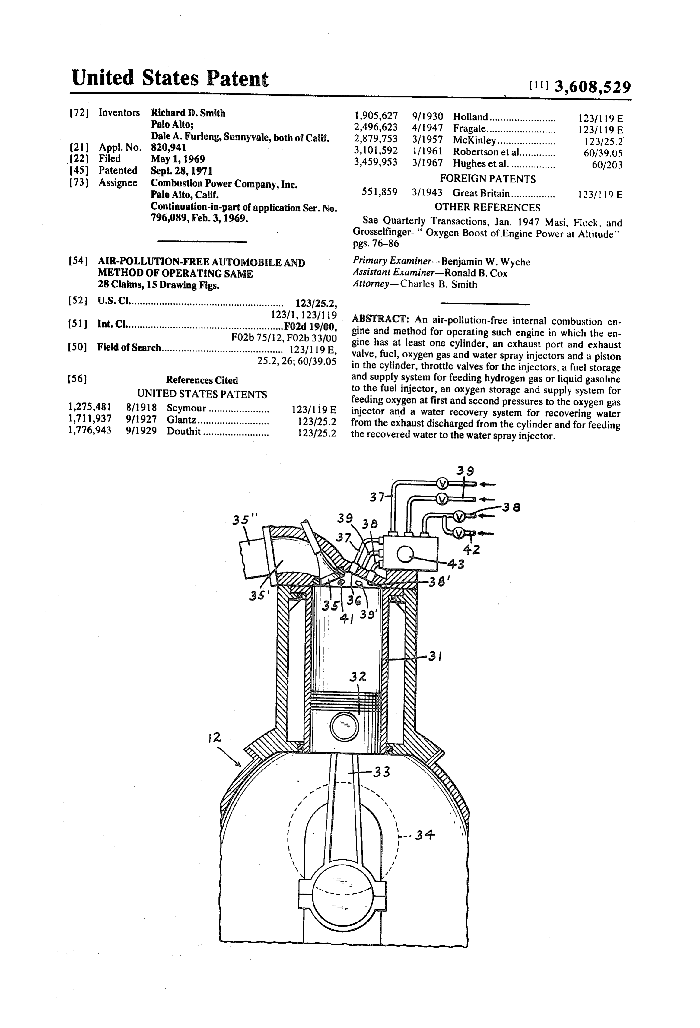
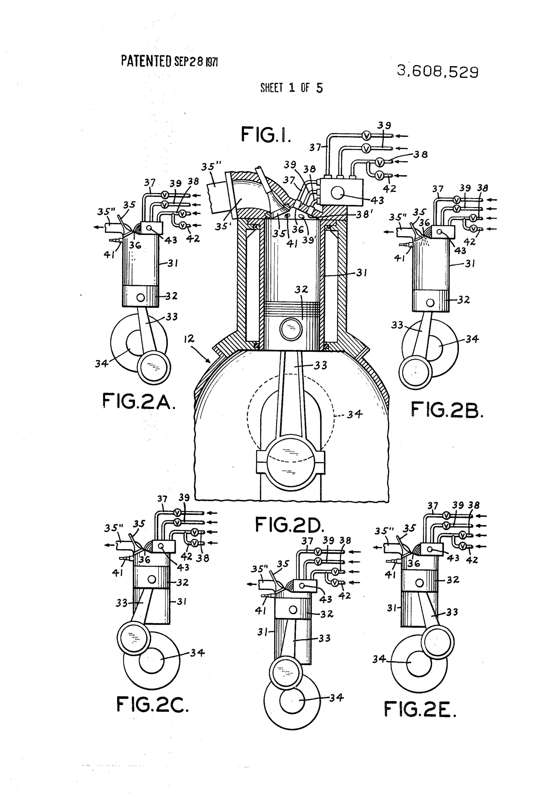
replace current cars. FIG. 1 is an elevational sectional view of a portion of one The first approach is being vigorously pursued by automo cylinder of an air-pollution-free engine in accordance with the tive manufacturers and major oil companies because, if suc present invention in which, in one embodiment, the engine is cessful, it would require minimum change to the automobile as we know it today. Difficult technical problems are involved 30 operated with hydrogen-oxygen and, in another embodiment, and long term laboratory research programs are anticipated. with gasoline-oxygen;
One of the most difficult problems in this approach is the operation2A-2E
FIGS. are schematic elevational views of the engine in accordance with the present invention illustrating elimination of oxides of nitrogens.
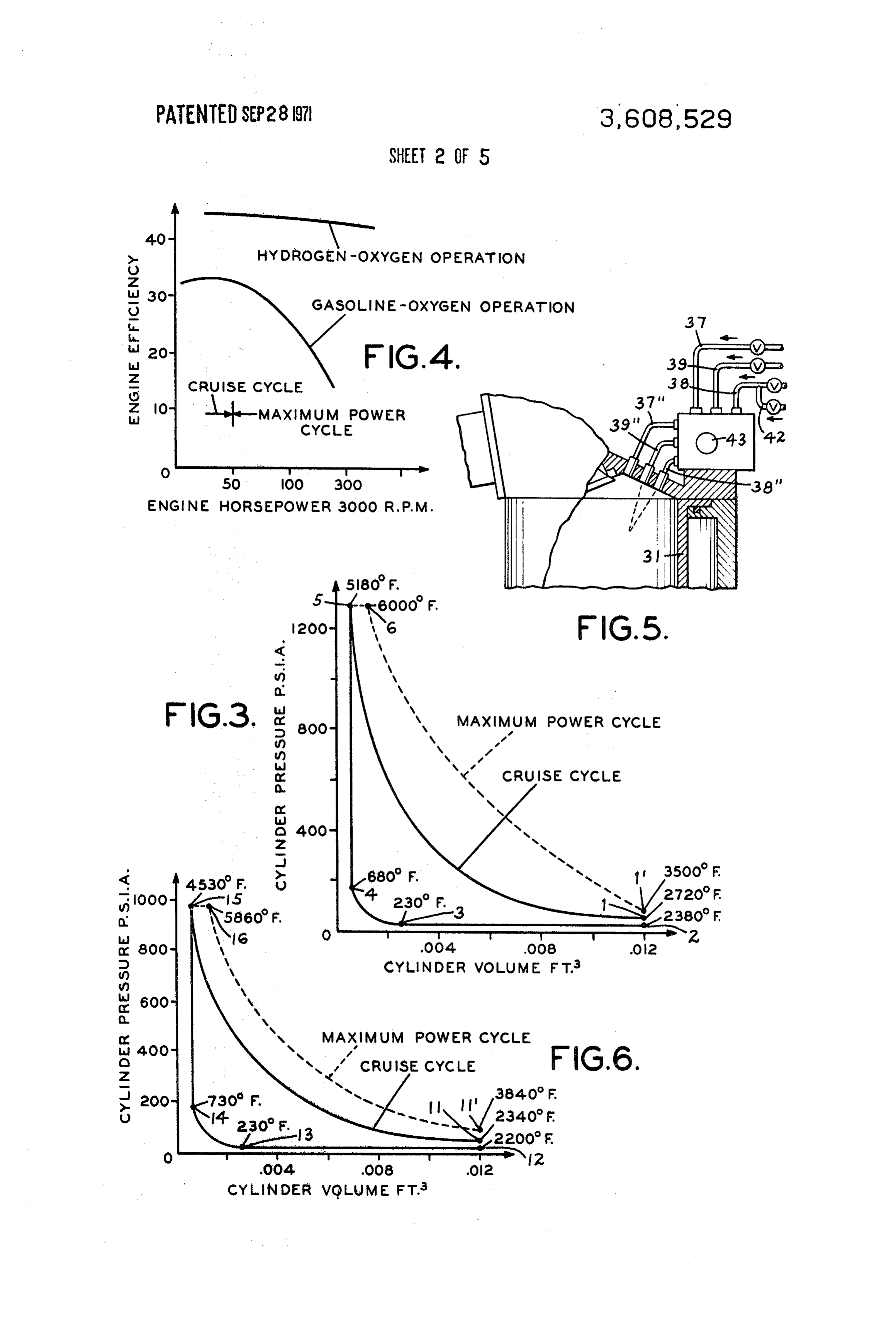
The external combustion engine approach requires com 35 theFIG. operating cycle of the engine;
3 is a graph of cylinder pressure versus cylinder promises in performance, convenience, or economy com volume for pared to current automobiles. Such external combustion en operation; the engine of FIG. 1 using hydrogen-oxygen for the gines are expensive to develop and require drastic changes in FIG. 4 is a graph of engine efficiency versus horsepower in the production tooling of the major automobile manufac which graph courses for operation with hydrogen-oxygen and turers. More importantly, however, such external combustion 40 gasoline-oxygen are shown;
engines are not completely pollution free.
Of the three approaches, the electric car is the only one FIG. 5 is an elevational sectional view of a portion of the en completely pollution free. Unfortunately, it is also the ap gine structure of FIG. 1 showing a portion of the operating proach which requires the most research in order to provide a cycle with gasoline-oxygen;
car that meets today's standards of performance, comfort, and 45 volume, 6similar
FIG. is a graph of cylinder pressure versus cylinder to FIG. 3 but using gasoline-oxygen for the convenience.
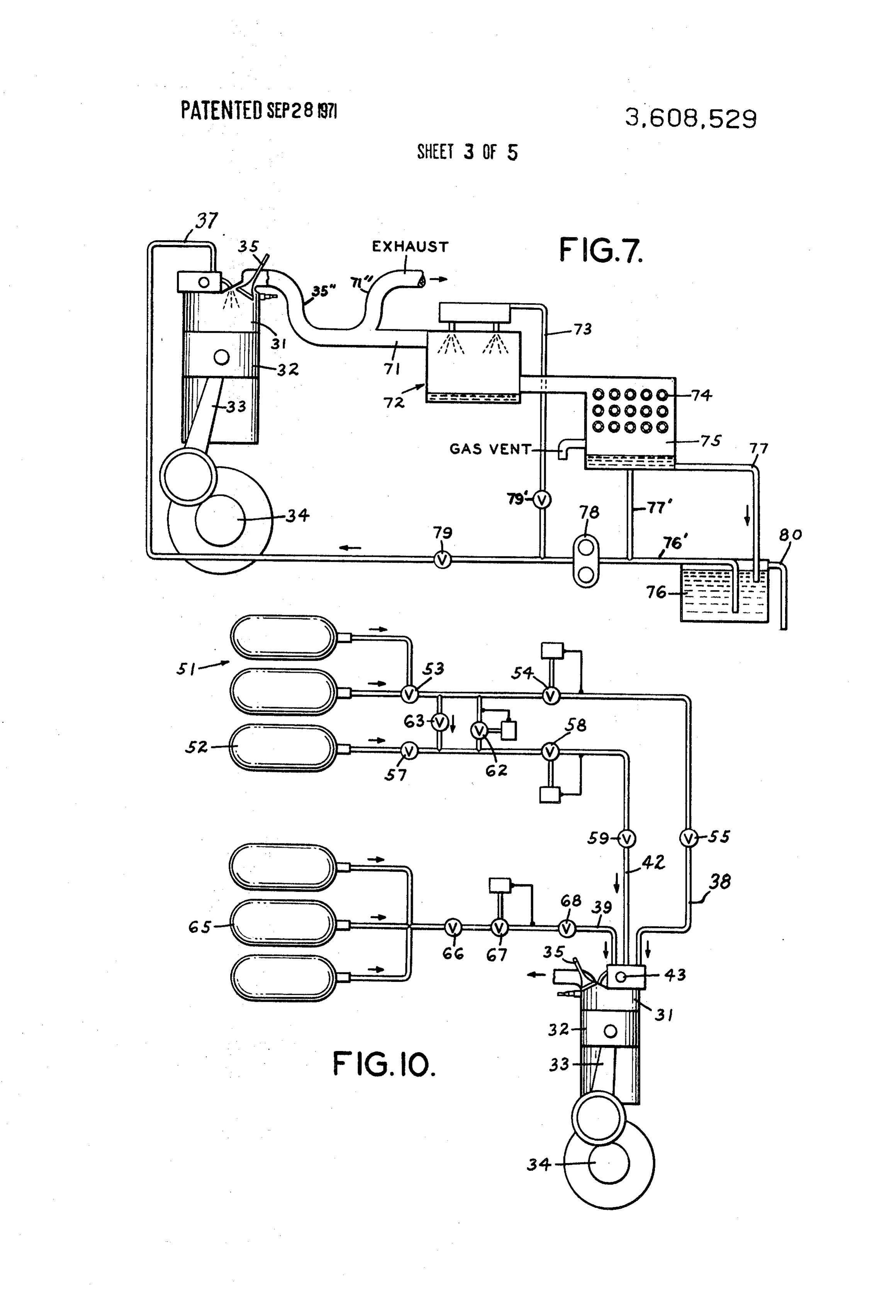
The present invention is directed to an air-pollution-free in operation;
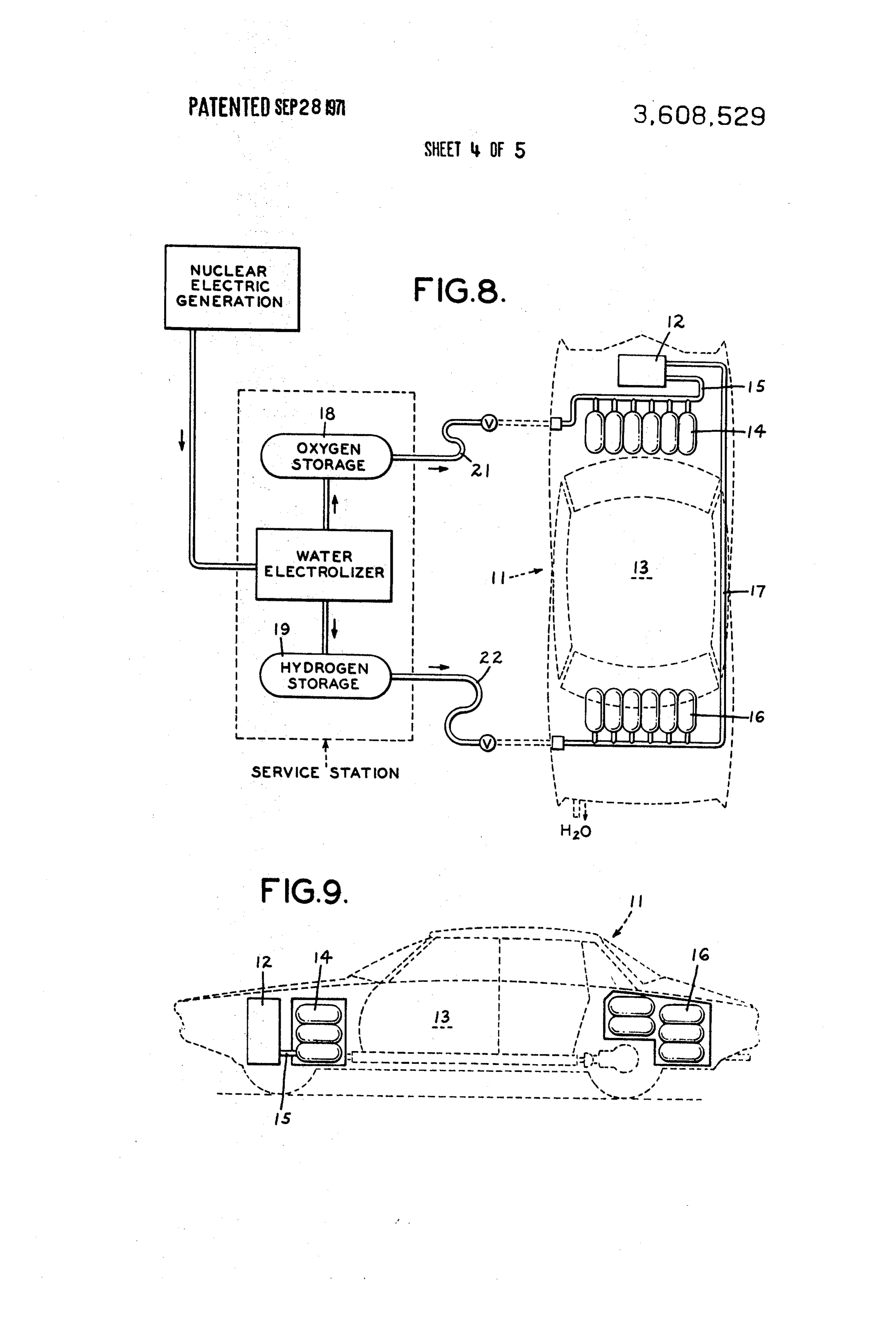
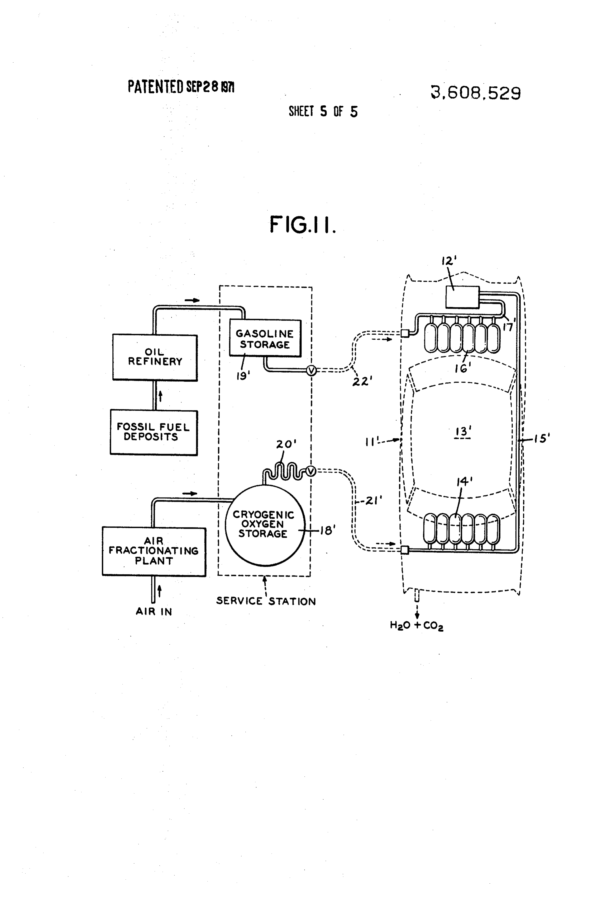
FIG. 7 is a drawing schematically illustrating the water spray ternal combustion engine and automobiles powered thereby and method of operating the same wherein the engine includes andFIG. water recovery system of the present invention; 8 is a schematic view, partially in block diagram form at least one cylinder, a piston reciprocating in the cylinder, 50 and an exhaust port and inlet injectors opened and closed and partially in plan, schematically illustrating the adaption of cyclically as the piston reciprocates. The inlet injectors in the hydrogen-oxygen embodiment to an automobile; clude a fuel supply inlet, a nitrogen free oxidant inlet, and a FIG. 9 is a schematic elevational view of the automobile il water inlet. Steps and means are provided for supplying con lustrated in FIG.8;
trolled amounts of fuel and oxidant to the cylinder for substan 55 FIG. 10 is a schematic illustration of the gas supply system tially complete combustion therein and for water spraying the for an engine in accordance with the present invention; and cylinder and piston during the exhaust cycle. The engine fuel FIG. 11 is a schematic view, partially in block diagram form is either liquid gasoline or gaseous hydrogen and the nitrogen and partially in plan schematically illustrating the adaption of free oxidant for both fuels is substantially pure oxygen. the gasoline-oxygen embodiment to an automobile. In accordance with this invention, an engine is provided 60 As set forth above, the present invention is directed to an which is air pollution-free. With hydrogen as the fuel, the only air-pollution-free internal combustion engine and method of product of combustion is water and with liquid gasoline, the operating same. It will be appreciated that this engine can be products of combustion are water, carbon dioxide and other utilized for many purposes and is ideally suited for propelling nonpollutants. an automobile and in, combination with other aspects of the The engine can be produced with existing manufacturing 65 present invention, provides an air-pollution-free system of technology and achieves current standards for performance, vehicular travel. Therefore, the embodiment of the invention convenience, and economy. No unusual starting or warmup will be described in greater detail below as applied to an inter problems are introduced and periodic maintenance remains nal combustion engine for an automobile and the operational substantially unchanged. Once in production, cars with inter system for such engine and automobile.
mal combustion engines of the instant invention will cost ap 70 Under present day driving habits, the ideal engine for the proximately the same as family cars with conventional internal family sedan should provide maximum efficiency in the hor combustion engines and trips to the gas station will be of sepower range of about 25 to 50 horsepower yet be capable of equivalent frequency and cost. . . - a maximum power of 200 horsepower and torque of 250 lb.- In accordance with another aspect of the present invention, 75 feet. A family car with such an engine requires an energy an air-pollution-free, two-stroke internal combustion engine is storage of about 134 horsepower hours delivered to the
Page 8
wheels. These requirements are difficult to meet with conven With the pressure of oxygen at 1,600 p.s.i.a. as hereinafter tional foursstroke gasoline engines because the maximum described, 300 p.s.i.a. pressure drop is provided through the power output of such conventional four-stroke gasoline en oxygen metering valve. The oxygen is throttled upstream of gine is directly proportional to the weight flow of air. There the metering valve to provide throttling for maximum power fore, at any given engine speed, power and torque are in 5 and concurrent throttling of the fuel injected prior to top dead creased by increasing the displacement of the engine. Con center is also provided.
sequently, conventional four-stroke engines used in family In one embodiment of the invention, hydrogen as is used as cars tend to have rather large displacements in order to meet fuel and oxygen gas is used as the oxidant. In another embodi the maximum power requirements; 300 cubic inches is con 10 ment, liquid gasoline is used as the fuel and oxygen gas as the sidered normal today. When these engines are operated at 25 oxidant. Because, as will be described in more detail later to 50 horsepower, which is the normal range at the more com herein, the hydrogen and oxygen gases are at sufficient pres mon driving speeds and only a fraction of maximum power, sure, such gases are delivered from the respective storage maximum gas temperatures and pressure in the cylinders are tanks to the throttling valves and metering valves driven by the reduced greatly because of heat transfer to the large surface 15 auxiliary cam on shaft 43 through appropriate lines connected area within the combustion chamber. Thermal efficiency and to the respective storage tanks. When liquid gasoline is used as engine efficiency at normal driving speeds is thereby sacri the fuel, the gasoline is pumped from the storage tank, which ficed. Combustion efficiency of such engine is also sacrificed is at atmospheric pressure, to the throttling and metering and air pollution is substantially increased. valves, the pump providing sufficient pressure so that the In the engine in accordance with the instant invention, high 20 liquid gasoline, in the required amount, can be injected into efficiency is accomplished in the more common driving speed the cylinder. For this purpose, a pump driven in conventional range of 25-50 horsepower with a two-stroke engine which is manner from crankshaft 34 and having suitable throttling and less than one-third the size of an equivalent conventional four metering means may be employed. Similarly, such a pump is stroke gasoline engine of the type currently used automobiles. also employed for feeding the water at sufficient pressure for Because of the reduction in size, the reduction in the number 25 spray cooling each cylinder. Because both the gasoline, when of strokes, and increase in cylinder pressure during normal, or used, and the water are injected at relatively low pressure, and cruise operation, the thermal efficiency and engine efficiency need not be precise, the use of more expensive and precise in are substantially improved over conventional four-stroke en jector pumps is not required in the practice of the present in gines. The instant two-stroke engine can, however, be vention.
produced with internal combustion tooling now in use for 30 The engine in accordance with the present invention and its producing conventional four-stroke gasoline engines. operation are unique in that water vapor, rather than nitrogen For purposes of illustration, the instant invention is applied gas, such as is the case when air is used in conventional en to a two-stroke engine having four-in-line cylinders each con gines as the oxidant, is the principal fluid utilized as the work nected by a connecting rod to a common crankshaft. The en ing fluid. Furthermore, the cylinder walls are cooled with in gine includes a conventional coolantjacket, coolant pump, ig 35 ternal water spray. The operation of the engine utilizes the nition distribution system, exhaust valve and, except as Otto cycle (constant volume combustion) for normal operat hereinafter noted, conventional accessories and timing ing power and combines the Otto cycle with the diesel cycle mechanisms. (constant pressure combustion) for higher power. For exam Referring to FIG. 1, showing one cylinder of the two-stroke, 40 ple, in the automobile engine embodiments described, the otto four-cylinder, in-line engine illustrating the instant invention, portion of the engine cycle is used for power levels up to each cylinder has a bore of 2.6 inches and a stroke of 4 inches. cruise power (40-50 horsepower), and is combined with the The exhaust is removed from cylinder 31 through single over diesel cycle for higher power.
head valve 35 via exhaust port 35' and exhaust manifold 35' Referring to FIG. 7, water for internal water spray cooling with valve 35 operated by an overhead cam driven in conven 45 of the cylinder walls and pistons of the engine of the present tional manner, not shown. With an expansion ratio of 20:1, the invention is provided by condensing the water vapor of the volume of each combustion chamber is 1.04 cubic inches. The working fluid and cooling spray from the exhaust. Exhaust engine, generally designated 12, uses the crankshaft from a manifold 35'' is connected, by line 71, to the top of desuper conventional internal combustion engine having a 4-inch heater 72, connected near its bottom to condenser 75. stroke. The water injector 36, oxygen injector 38', fuel injec 50 Because the amount of water for water spray cooling is less tor 39' and sparkplug 41 are all located in the head. Water in than the amount of water vapor exhausted through exhaust jector 36 is centered in the bore to provide a uniform spray to valve 35 and manifold 35', a part of the exhaust may be piston 32 and walls of cylinder 31. Water, fuel and oxygen are discharged, through line 71', to the atmosphere. Water or metered by valves driven by an auxiliary cam on shaft 43 in coolant from the radiator and coolant system of engine 12 is turn driven in conventional manner, not shown, from 55 circulated through coil 74 in condenser 75. Water condensed crankshaft 34. The fuel metering valve is separated from the from the exhaust in condenser 75 is discharged through line oxygen metering valve to provide complete separation of the 77 into reservoir 76, having overflow 80 for discharging excess materials until injection into the combustion chamber. A typi water to the atmosphere and, through line 77', to line 76', cal engine constructed in accordance with the present inven connected, at one end, to reservoir 76 and, at its other end, to tion is 27 inches long, 25 inches high, 15 inches wide, and 60 pump 78. From pump 78 the water is fed, through throttle weighs approximately 220 pounds. valve 79, to water spray injector 36, and, through valve 79' The fuel and oxygen injected prior to ignition for the cruise and line 73, to the spray head in desuperheater 72. Desuper portion of the cycle are injected over a crankshaft travel of heater 72, condenser 75, reservoir 76, pump 78 and the vari about 45° for 1.5 milliseconds at 5,000 rp.m. The dwell angle ous lines, are provided with small vents so that, after engine 12 of injection remains constant, and the amount of fuel and ox 65 is shut down, any water remaining in the system will be ygen injected is determined by throttling in the respective feed discharged to the atmosphere. In this way, freezing of the lines upstream of the metering valves driven by the auxiliary system is avoided where atmospheric temperature is below cam on shaft 43. freezing and the engine is shut down for any extended period During the maximum power portion of the cycle, all of the of time.
fuel and a portion of the oxygen are injected over the same 70 With the exhaust recovery system of the instant invention crankshaft travel and for the same length of time as in the for recovering water from the engine exhaust, the need for cruise portion. The remaining portion of the oxygen to water storage for internal water spray cooling of the cylinders complete the combustion of the fuel is injected after top dead and pistons is avoided. When the engine is first started, the center over a fixed dwell, for example, about 30 of crankshaft 75 cylinder walls, pistons, engine coolant temperature and ele travel for 1 milliseconds at 5,000 r.p.m. ments of the exhaust recovery system are at a relatively low
Page 9
temperature. Thus, when the engine is first started, internal compression, are similar to those of the single power cruise cy water spray cooling is not required but is required after the cle, except that pressure is slightly greater due to the pressure cylinder walls and pistons heat up. While this heating up is tak of the additional hydrogen and oxygen. Ignition occurs at top ing place, the water vapor from the exhaust is being con dead center by means of a spark ignition from spark plug 41 densed and collected in the recovery system so that, when and the fuel rich mixture burns to produce superheated vapor. required for water spray cooling of the cylinder walls and Concurrently, FIG. 2E) a valve in a high-pressure oxygen line pistons and for spraying in desuperheater 72, water will be 42 is opened to supply additional oxygen to burn the remain available in reservoir 76. If, of course, the engine is shut down ing unreacted hydrogen at a constant pressure and initiate the and restarted before the cylinder walls, pistons and recovery second power cycle. Under circumstances where detonation system has cooled down, the water remaining in the recovery 10 occurs, the hydrogen may be injected on the upstroke as system from the earlier engine operation is available for im described above, but the oxygen injection may be delayed and mediate water spray in the cylinders through spray injector 36. initiated shortly before top dead center so as to progressively Referring now to FIGS. 2A-2B, there is illustrated the burn the hydrogen as the oxygen is admitted. cruise cycle portion of the engine in accordance with the em 15 For a clear understanding of the present invention, the bodiment of the invention is which hydrogen gas is employed parameters of an illustrative embodiment are given and as the fuel and substantially pure oxygen gas as the oxidant. operating characteristics are shown in the pressure versus With particular reference to FIG. 2A, there is shown one of volume graph of FIG. 3. As shown at the end of the expansion the engine cylinders 31 including a working member or piston stroke of the cruise single power cycle (FIG. 2A), the cylinder 32 therein connected via connecting rod 33 to drive shaft 34. pressure is 39 p.s.i.a. and the superheated vapor temperature The piston 32 is illustrated near the end of the power stroke is 2,720 F. (Point 1 in FIG. 3). When the exhaust valve opens, after combustion of gaseous hydrogen and substantially pure the vapor expands adiabatically from 39 p.s.i.a. to 20 p.s.i.a. oxygen. The products of combustion and the working fluid reducing the vapor temperature to 2,380 . F. (Point 2 in FIG. (both superheated water vapor) have been expanded, such as 3). At these temperatures, the speed of sound in water vapor is 20:1, and the exhaust valve 35 is about to open. 25 approximately 3,000 ft/sec. and it takes approximately one The exhaust valve 35 opens just before bottom dead center tenth milliseconds for the pressure waves to reach the piston and the hot gas in the cylinder blows down to low pressure, the (or 3 of crankshaft rotation at 5,000 rp.m.) before the flow gas in the cylinder expanding adiabatically. Shortly after the starts out of the cylinder after the valve has first opened. blowdown of the superheated vapor in the cylinder, water in For providing the water spray during the exhaust stroke of jection is initiated through injector 36 to cool the cylinder 30 the cycle, the injector 36 can have a pressure differential of walls, pistons, and exhaust valve (see FIG. 2B). The exhaust 120 p.s.i.a. from water line 37, causing the water spray to at valve 35 is left open until the piston has changed the volume tain a velocity of approximately 100 ft/sec. Consequently, ap ratio, such as where only a 5:1 volume ratio remains, and then proximately 2 milliseconds is required for a droplet of water of the exhaust valve 35 is closed (see FIG. 2C). During this ex the spray to reach a point on the cylinder wall 3 inches from haust portion of the stroke, the piston 32 has scavenged the 35 the top of the combustion chamber. At 5,000 rp.m. this travel majority of the high temperature vapor from the cylinder. requires about 60 of crankshaft travel and, if the water spray Some of the vapor will be cooled directly by vaporizing the in is initiated at bottom dead center, the droplet will reach the jected water as it is sprayed toward the wall. The water hitting wall at the above referred to location shortly before the piston the walls, piston crown, and exhaust valve will flash into low coversit.
temperature steam, mixing with the residual high-temperature 40 At the time when the exhaust valve 35 closes (Point 3 in water vapor and cooling it further. Some of this steam will pass FIG. 3), substantially only saturated steam at about 230 F. out the exhaust valve along with the residual vapor. At the remains above the piston and compression begins. time the exhaust valve is closed, the volume remaining above The maximum pressure in the cylinder rises only to 165 the piston in the cylinder is filled with saturated steam. p.s.i.a. Consequently, the back pressure against the injected At the time of closing the exhaust valve 35, injection of 45 gas during injection is minimal. Adiabatic compression of the gaseous hydrogen and oxygen from injectors 38 and 39, steam at 230 F. (over a 5:1 compression ratio) plus the in respectively, is initiated. This injection occurs between closing troduction of hydrogen and oxygen results in a cylinder pres of the exhaust valve and several degrees of crankshaft rotation sure of 165 p.s.i.a. and a gas temperature of 680 F. (Point 4 in before top dead center. FIG. 3). After ignition, the cylinder pressure increased to FIG. 2D shows ignition at top dead center where com 50 about 1,300 p.s.i.a. and the temperature of the vapor therein bustion begins and increases the pressure and temperature in to about 5, 180 F. (Point 5 in FIG. 3). Then, with expansion the cylinder. Next, the superheated vapor is expanded 20:1 to during the working stroke, the pressure and temperature provide the work output. The superheated vapor transfers return to that at point 1 in FIG.3.
heat to the walls which, in addition to cooling by the water 55 In the maximum dual power cycle operation, the power jacket, are also cooled by the internal water spray on the ex stroke ends with superheated vapor at a pressure of 71.5 haust upstroke. p.s.i.a. and a temperature of about 3,500 F. (Point 1 in FIG. To obtain maximum power, above the single power cycle ef 3). Upon opening of the exhaust valve, the superheated vapor ficient cruise power range, the engine operation described in the cylinder expands adiabatically to a pressure of 20 p.s.i.a. above is augmented by a second power cycle by post ignition 60 and a temperature of 2,760 F., and, after the water spray and injection. FIGS. 2A-2D and FIG 2E illustrate the various steps exhaust, saturated vapor remains at 230 F. and 20 p.s.i.a., the of the power cycles. At the end of the power stroke (FIG. 2A), same conditions existing for the cruise single power cycle before the exhaust valve opens, the vapor in the cylinder is at a (Point 3 in FIG. 3). During compression and fuel and oxygen temperature and at a pressure above that at the end of the sin injection, only that part of the oxygen is injected to reach a gle cruise cycle power stroke. After the exhaust valve opens, 65 maximum cylinder pressure of 1,300 p.s.i.a. This results in an the cylinder blows down, expanding the vapor in the cylinder oxygen-to-fuel ratio of 2.6, well within the combustion limits. adiabatically. Water spray is initiated (FIG. 2B) at bottom The overall oxygen to fuel ratio for hydrogen-oxygen com dead center, as it was for the cruise cycle. The water spray is bustion is O/F 8, the stoichiometric ratio. After ignition, the increased by increasing the flow rate to provide additional fuel rich hydrogen and oxygen mixture burns to produce su water for cooling at this higher power. After the closing of the 70 perheated vapor at 1,300 p.s.i.a. and additional high-pressure exhaust valve 35 (FIG. 2C), and during the compression oxygen is injected until all the hydrogen has burned. The su stroke, all of the hydrogen fuel is injected but only that portion perheated vapor reaches about 6,000 F. (Point 6 in FIG. 3). of the oxygen is injected which can be injected without caus At the start of the expansion stroke, the expansion ratio has ing detonation or failure of the cylinder or piston because of been reduced from 20:1 to 8.5:1 by the previous constant over pressure. The conditions in the cylinder, at the end of 75 pressure expansion (Point 6 on the diagram of FIG. 3) for the
Page 10
maximum power cycle in addition to that of the cruise power because the element nitrogen is not present in the cylinder. cycle. The engine, as described, produces 216 horsepower at Furthermore, when the gasoline is burned in the highly con 3,000 rp.m. when operating at conditions as discussed for the centrated oxygen environment of this invention, intimate con maximum dual power cycle. tact between the gasoline molecules and the oxygen molecules The engine efficiency of the hydrogen-oxygen engine is il is accomplished. Compared to the combustion of the same lustrated in FIG. 4 as a function of engine horsepower at a fuel in air, the burning rate is increased; the temperature of constant speed of 3,000 r.p.m. The curve peaks at an efficien the products of combustion is higher; and thoroughness of cy of 45 percent at 60 horsepower (slightly more than combustion of the fuel is assured.
required for normal driving) but drops off very little at the 10 Because, in internal combustion engines using air and higher horsepower levels of the maximum dual power cycle. gasoline, air contains about 78 percent nitrogen and 21 per One would normally expect a sharper drop off at the higher cent oxygen by volume, and 75.8 percent nitrogen and 23.2 powers because the expansion ratio is greatly reduced due to percent oxygen by weight, the diluting effect of nitrogen can the constant pressure portion of the cycle (post ignition injec well be appreciated. Nitrogen does not contribute to the ox tion). However, this trend toward lower efficiencies is offset idation process but acts to dilute the effective oxygen concen by the increasing temperature of the superheated vapor in the 15 tration, making it more difficult for an oxygen molecule to cylinder, tending toward increasing the efficiency. find a fuel molecule with which to react. In addition to its role In accordance with another embodiment of the invention, as a diluent, the nitrogen also acts as a heat sink to absorb the gasoline and oxygen, rather than hydrogen and oxygen, are energy released in the chemical reaction. The nitrogen is burned to provide a two-cycle internal combustion engine in 20 heated along with the products of the reaction and, because it which the maximum efficiency is in the 25-50 horsepower is present in such large quantities, it reduces the maximum range yet such engine is capable of maximum power of 200 temperature of the fuel-air reaction, reducing thermal effi horsepower and 250 lbs.-ft. of torque. For purposes of com ciency for maximum power.
parison, the engine in accordance with this embodiment is The engine efficiency, of the gasoline-oxygen engine, is il designed with the same displacement, bore and stroke as the 25 lustrated, in FIG. 4, as a function of engine horsepower at a air-pollution-free engine utilizing hydrogen and oxygen constant speed of 3,000 rp.m. The difference between the ef described above. The engine burning gasoline and oxygen ficiencies of the hydrogen-oxygen and gasoline-oxygen em operates basically on the same cycle as the hydrogen and ox bodiments is explained by the low molecular weight of water ygen-burning engine but derives its pollution-free potential vapor (18) compared to carbon dioxide (44). The gasoline from completely oxidizing the hydrocarbons in gasoline in the 30 burned in the gasoline-oxygen engine produces carbon diox absence of nitrogen. Consequently, oxygen rich mixtures can ide which supplies only 40 percent of the work of water vapor be used to thoroughly oxidize the fuel without the usual during the expansion process because of the difference in production of nitrogen oxides as is the case in conventional molecular weight. The effect of the carbon dioxide becomes engines where air is employed. increasingly pronounced as power is increased because the The operation of the engine in accordance with this em 35 relative percentage of carbon dioxide is similarly increased, At bodiment conforms generally to the operation described cruise power, the water vapor diluent is more effective in above with reference to FIGS. 2A-2E but wherein liquid reducing the average molecular weight of the working fluid. gasoline instead of gaseous hydrogen is directed into the In the illustrative embodiments, sufficient water is sprayed cylinder through line 39. The gasoline is burned in a gas mix into each cylinder of each exhaust stroke to cool the cylinder ture with a high oxygen concentration and, typically, with 15 40 and piston. During operation of the engine at maximum power percent excess oxygen. As a result, at the end of the com more water spray is required than for cooling at normal cruise bustion stroke, as shown in FIG. 2A, the hydrocarbons of the power. For example, in the hydrogen-oxygen embodiment, ap gasoline are completely oxidized to water and carbon dioxide. proximately 0.00015 pounds of water are required for water The same Otto cycle and diesel cycle, as described above, are 45 spray on each exhaust stroke at normal cruise power and ap utilized for the cruise, single power cycle and maximum dual proximately 0.0004 pounds per stroke at maximum power. power cycle operations of the engine. Such water is injected into cylinder 31, through spray head 36, As illustrated in FIG. 5, the gas fuel inlet port 39" is ar FIG. 1, as a medium fine spray. If too fine, the spray will be ranged with respect to the gaseous oxygen inlet port 38' such evaporated and will not reach the cylinder wall and piston that within the cylinder 31' the jet of oxygen from inlet port 50 crown for cooling. If too coarse, the spray will not distribute 38' hits the stream of liquid gasoline entering through port uniformly on the cylinder walls. Preferably, only nominal pres 39' whereby the gasoline is finely atomized and dispersed sures, such as 120 p.s.i.a., are employed at the water spray throughout the combustion chamber within the cylinder. The nozzle. The amount of water to be sprayed is controlled by gasoline and oxygen are not mixed prior to introduction into valve 79, FIG.7.
the cylinder for reasons of safety. 55 The engine of the instant invention, whether the embodi The graph showing cylinder pressure versus cylinder ment in which the fuel is hydrogen or gasoline, may be in volume for the engine burning liquid gasoline and gaseous ox stalled in the front or rear of the automobile, depending upon ygen is illustrated in FIG. 6 wherein points 11-16 correspond, the automobile design, and is coupled to the drive gear in con respectively, with points 1-6 described above with reference ventional manner as, for example, by a conventional transmis to FIG. 3 in setting forth the operation of the engine burning 60 sion, torque converter, or the like. The storage tanks, whether hydrogen and oxygen. hydrogen and oxygen gases, or gasoline and oxygen gas, are As with the engine burning hydrogen and oxygen, all of the located in the vehicle at a convenient location, where they are gasoline is introduced prior to ignition and an amount of ox out of the way, and can be conveniently filled. Preferably, ygen is introduced consistent with obtaining the maximum however, the tanks are located as separate locations in the chamber pressure. By introducing all of the gasoline prior to 65 vehicle in the interest of safety.
ignition, the subsequent burning of the highly gasoline rich Referring now to FIGS. 8 and 9, two-stroke internal com mixture thoroughly vaporizes the excess gasoline and heats it bustion engine 12 of the instant invention is located in the to combustion temperatures. Consequently, when oxygen is front of passenger compartment 13 of the vehicle, generally finally introduced, the fuel will burn quickly and thoroughly. designated 11. In this embodiment combustion fuel for engine In this gasoline-oxygen embodiment of the invention, the 70 12 is provided from hydrogen tanks 16 located at the rear of hydrocarbon fuels are burned substantially completely to compartment 13 and connected to engine 12 by line 17 and eliminate air polluting carbon monoxide, unburned hydrocar oxidant from oxygen tanks 14 located at the front of passenger bon and nitrogen oxides normally resulting from the use of compartment 13 and connected to engine 12 by line 15. Ox gasoline and air in internal combustion engines. The produc ygen tanks 14 are refilled or recharged from an oxygen storage tion of nitrogen oxide is not possible in the instant invention 75 tank, such as tank 18 at a service station, through line 21 hav
Page 11
ing a quick connect coupling for connection to a suitable The terms and expressions which have been employed are fitting on the vehicle and hydrogen tanks 16 are refilled or used as terms of description and not of limitation, and there is recharged in a similar manner from hydrogen storage tanks 19 no intention in the use of such terms and expressions of ex through line 22. cluding any equivalents of the features shown and described Referring to FIG. 10 there is shown a schematic diagram of 5 or portions thereof, but is is recognized that various modifica the storage and injection system for the oxygen gas for the en tions are possible.
gine of the instant invention. The oxygen gas is stored initially What is claimed is:
in the storage tanks at a pressure in excess of the injection 1. An air-pollution-free internal combustion engine com pressure. For example, the gas is stored in the storage tanks at prising:
5,000 p.s.i.a. The gas injection system of the illustrative em 10 1. at least one cylinder;
bodiments utilizes the lowest possible gas injection pressure, 2. a piston reciprocating in said cylinder; 600 p.s. i.a. to take maximum advantage of the capacity of the 3. an exhaust port in said cylinder; storage tanks. If the pressure drops below the gas injection 4. an exhaust valve in said port; pressure, the engine begins to lose power, thereby warning the 15 5. a fuel injector in said cylinder; driver to stop at a service station and recharge the tanks. A 6. an oxygen injector in said cylinder for injecting substan special high-pressure oxygen system is used for post ignition tially pure oxygen gas as the sole combustion oxidant; for the maximum power cycle. 7. a water spray injector in said cylinder; As illustrated, the oxygen storage tanks are segregated into 8. means for supplying a metered amount of fuel to said fuel two groups, cruise oxygen tanks 51 and maximum power ox 20 injector;
ygen tanks 52. Typically, the cruise oxygen tanks are on the 9. means for supplying substantially pure oxygen to said ox order of 90 percent of the total tanks. Cruise oxygen from ygen inlet injector in a metered amount at least sufficient tanks 51 goes through a shutoff valve 53, actuated by the igni for complete combustion of said metered amount of fuel; tion key, and a pressure reducing regulator 54 to reduce the 10. means for supplying water to said water spray injector in oxygen pressure to approximately 500 p.s.i.a. At the engine 25 a metered amount sufficient to cool the piston cylinder 12, oxygen passes through a throttling valve 55 controlled by wall, and exhaust gas by vaporization of the water; the automobile accelerator (not shown) and metering valve 11, means for cyclically opening and closing the exhaust driven by shaft 43 to inject the oxygen into the cylinder at the valve in said exhaust port;
propertime of the cycle. 12. means for injecting said metered amounts of oxygen into The oxygen from tanks 52 to provide maximum power goes said cylinder;
through a shutoff valve 57 and a pressure reducing regulator 30 13. means for injecting said metered amounts of fuel into 58 to a pressure above the constant pressure level of the cruise said cylinder;
power cycle, for example, to a pressure of 1,600 p.s.i.a., and 14. means for igniting the injected mixture of fuel and ox then through throttle valve 59. To insure complete utilization ygen to produce combustion; and of all oxygen, a valving assembly is provided for connecting 35 5. means of injecting said metered amounts of water into the conduits of the cruise power cycle oxygen tanks 51 and said cylinder during the exhaust stroke to cool the piston, maximum power oxygen tanks 52, respectively, when either cylinder wall and exhaust gas, without causing substantial the pressure in the cruise oxygen tanks falls to 500 p.s.i.a. or cooling of the hot gas during combustion and expansion. the pressure in the power oxygen tanks falls to 1,600 p.s.i.a. 2. An air-pollution-free internal combustion engine com This valving assembly can include a regulator 62 which allows 40 prising:
oxygen from maximum power oxygen tanks 52 to bleed into 1. at least one cylinder;
the cruise power cycle line to maintain a pressure of 600 2. a piston reciprocating in said cylinder; p.s.i.a. in the cruise power cycle line and a check valve 63 3. an exhaust port in said cylinder; which allows oxygen from cruise power cycle tanks 51 to 4. an exhaust valve in said port; bleed into the maximum power oxygen line if pressure in max 45 5. a fuel injector in said cylinder;
imum power cycle oxygen tanks 52 drops below the pressure 6. an oxygen injector in said cylinder for injecting substan of the cruise tanks, tially pure oxygen gas as the sole combustion oxidant; The hydrogen storage and injection system, for the embodi 7. a water spray injector in said cylinder; ment of the invention utilizing hydrogen gas as the fuel, is 8. fuel storage means;
similar to the cruise power cycle oxygen system and include 50 9, oxygen storage means;
pressure tank 65, shutoff valve 66, pressure reducing valve 67, 10. means for feeding fuel from said fuel storage means to throttle valve 68 and injection valve 69. Throttle valve 68 in said fuel injector in a metered amount; troduces additional hydrogen into the cylinder during the 11. means for feeding oxygen from said oxygen storage maximum power cycle. means to said oxygen injector in a metered amount at in F.G. 11, the embodiment of the invention in which 55 least sufficient for complete combustion of said metered gasoline is used as the fuel and oxygen as the oxidant of the amount of fuel;
two-stroke internal combustion engine of the instant invention 12, means connected to said exhaust port for recovering is shown adapted to a passenger vehicle. Engine 12" is located water from the exhaust gas of the combustion of said fuel in front of passenger compartment 13' and combustion fuel is and oxygen in said cylinder, said exhaust gas discharged delivered to engine 12' from gasoline tank 16’ through line 60 from said cylinder through said exhaust port to said 17'. Gasoline tanks 16' and engine 12" are located at the front means for recovering water;
of passenger compartment 13'. Oxygen tanks 14' are located 13. means for supplying the water recovered from said ex at the rear of compartment 13' and are connected by line 15" haust gas by said means for recovering water to said water through engine 12'. Gasoline tanks 16' are refilled from spray injector in a metered amount sufficient to cool the gasoline storage tank 19', located at the service station, 65 piston, cylinder wall and exhaust gas by vaporization of through line 22' in the manner conventionally employed for the water;
the fueling of passenger vehicles with conventional four 14. means for injecting said metered amounts of fuel into stroke gasoline engines. Oxygen gas for refilling oxygen tanks said cylinder;
14" on the vehicle is fed from liquid oxygen storage tanks 18', 15, means for injecting said metered amounts of oxygen into located in the service station, through converter 20' and line 70 said cylinder;
21'. A suitable quick connect coupling is provided on the 16. means for injecting said metered amounts of water into vehicle and on the end of line 21" for feeding the oxygen from said cylinder during the exhaust stroke to cool the piston, converter 20' to oxygen tanks 14' and for closing off the con cylinder wall and exhaust gas without causing substantial nection, at the vehicle, when the end of line 21' is removed 75 cooling of the hot gas during combustion and expansion from the vehicle connection. of the gas;
Page 12
17. means for igniting the injected mixture of fuel and ox 5. a fuel injector, oxygen injector, and water spray injector ygen to produce combustion; and in said cylinder;
18. means for cyclically opening and closing the exhaust 6. means for supplying metered amounts of fuel, oxygen and valve in said exhaust port. water to their respective said injectors; 3. An engine, as recited in claim 2, in which said means for 7. means for injecting said fuel oxygen and water into said recovering water from said exhaust gas comprises a con cylinder;
denser, said condenser including coils and means for circulat 8. means for cyclically opening and closing the exhaust ing coolant from said engine through said coils. valve in said exhaust port, and 4. An engine, as recited in claim 3, in which said means for 9. means for igniting the injected mixture of fuel and oxygen recovering water from said exhaust gas comprises a desuper 10 to produce combustion, which comprises: heater, means for spraying water in said desuperheater and a. closing said exhaust port with said exhaust valve as said means for delivering water discharged from said condenser to piston reciprocates towards said exhaust port and said said water spray means in said desuperheater. fuel, oxygen, and water spray injectors, 5. An engine, as recited in claim 4, in which said means for b. injecting into said cylinder a metered amount of fuel recovering water from said exhaust gas comprises a reservoir, 15 and substantially pure oxygen gas as the sole com means for discharging exhaust and condensate, including bustion oxidant while said exhaust port is closed; water sprayed into said desuperheater, from said desuper c. combusting said fuel and oxygen gas in said cylinder, heater into said condenser, means for discharging exhaust and d. opening said exhaust valve after said fuel and oxygen condensate, including sprayed water, from said condenser into 20 gas are combusted and discharging the exhaust said reservoir and means for feeding water from said reservoir products of combustion from said cylinder, and to said water spray means in said desuperheater and to said e. spraying the cylinder, piston, and exhaust products of water spray injector in said cylinder. combustion with a metered amount of water during the 6. An engine, as recited in claim 2, in which said oxygen exhaust stroke, and without causing substantial cooling storage means includes a first set of interconnected oxygen of the hot gas during combustion and expansion. storage tanks, a second set of interconnected oxygen storage 25 16. A method as recited in claim 15 in which the water from tanks, means for feeding oxygen from said first set of storage the exhaust discharge from said cylinder through the open ex tanks to said oxygen injector, means for metering said oxygen haust valve is recovered from said exhaust and fed into said fed from said first set of storage tanks to said oxygen injector, cylinder through said water spray injector to cool said cylinder means for feeding oxygen from said second set of storage and piston.
tanks to said oxygen injector and means for metering said ox 30 17. A method as recited in claim 16 in which a portion of ygen fed from said second set of storage tanks to said oxygen the water recovered from said exhaust is sprayed into said ex injector. haust for cooling said exhaust.
7. An engine, as recited in claim 1, in which said oxygen 18. A method as recited in claim 15 in which a first metered storage means comprises a first set of interconnected oxygen 35 amount of oxygen gas is injected into said cylinder with said storage tanks, a second set of interconnected oxygen storage fuel and combusted and, while said first metered amount of tanks, means for feeding oxygen from said first set of storage oxygen gas and said fuel is being combusted, a second metered tanks to said oxygen injector, means for metering said oxygen amount of oxygen gas is injected into said cylinder and com fed from said first set of storage tanks to said oxygen injector, busted with fuel in said cylinder. 19. A method as recited in claim 17 in which said fuel is means for feeding oxygen from said second set of storage 40 hydrogen gas.
tanks to said oxygen injector and means for metering said ox 20. A method as recited in claim 17 in which said fuel is ygen fed from said second set of storage tanks to said oxygen liquid gasoline.
injector.
8. An engine, as recited in claim 7, in which said oxygen amount of 21. A method as recited in claim 19 in which a first metered storage means comprises means for feeding oxygen from said 45 fuel oxygen gas is injected into said cylinder with said first set of storage tanks to said means for feeding oxygen from and combusted and, while said first metered amount of said second set of storage tanks and means for feeding oxygen oxygen gas and said fuel is being combusted, a second metered from said second set of storage tanks to said means for feeding amount of oxygen gas is injected into said cylinder and com busted with fuel in said cylinder.
oxygen from said first set of storage tanks. 22. A method as recited in claim 20 in which a first metered 9. An engine, as recited in claim 2, in which said fuel is a 50 amount of oxygen gas is injected into said cylinder with said liquid hydrocarbon.
10. An engine, as recited in claim 8, in which said fuel is oxygen gascombusted fuel and and, while said first metered amount of and said fuel is being combusted, a second metered gasoline.
11. An engine, as recited in claim 2, in which said fuel is amountbusted of oxygen gas is injected into said cylinder and com with fuel in said cylinder.
hydrogen gas. 55 23. An engine as recited in claim 1 wherein said fuel is a 12. An engine, as recited in claim 8, in which said fuel is liquid hydrocarbon.
hydrogen gas.
13. An engine, as recited in claim 11, in which said 24. An engine as recited in claim 1, wherein said fuel is gasoline.
hydrogen gas fuel storage means comprises a set of intercon 25. An engine as recited in claim 1, wherein said fuel is nected storage tanks, means for supplying hydrogen gas from 60 hydrogen.
said storage tanks to said fuel injector, said means for supply 26. An engine as recited in claim 1, wherein said means for ing said hydrogen gas including means for regulating the flow igniting the injected mixture is a spark plug and further includ of said hydrogen gas through said supplying means. 1ng:
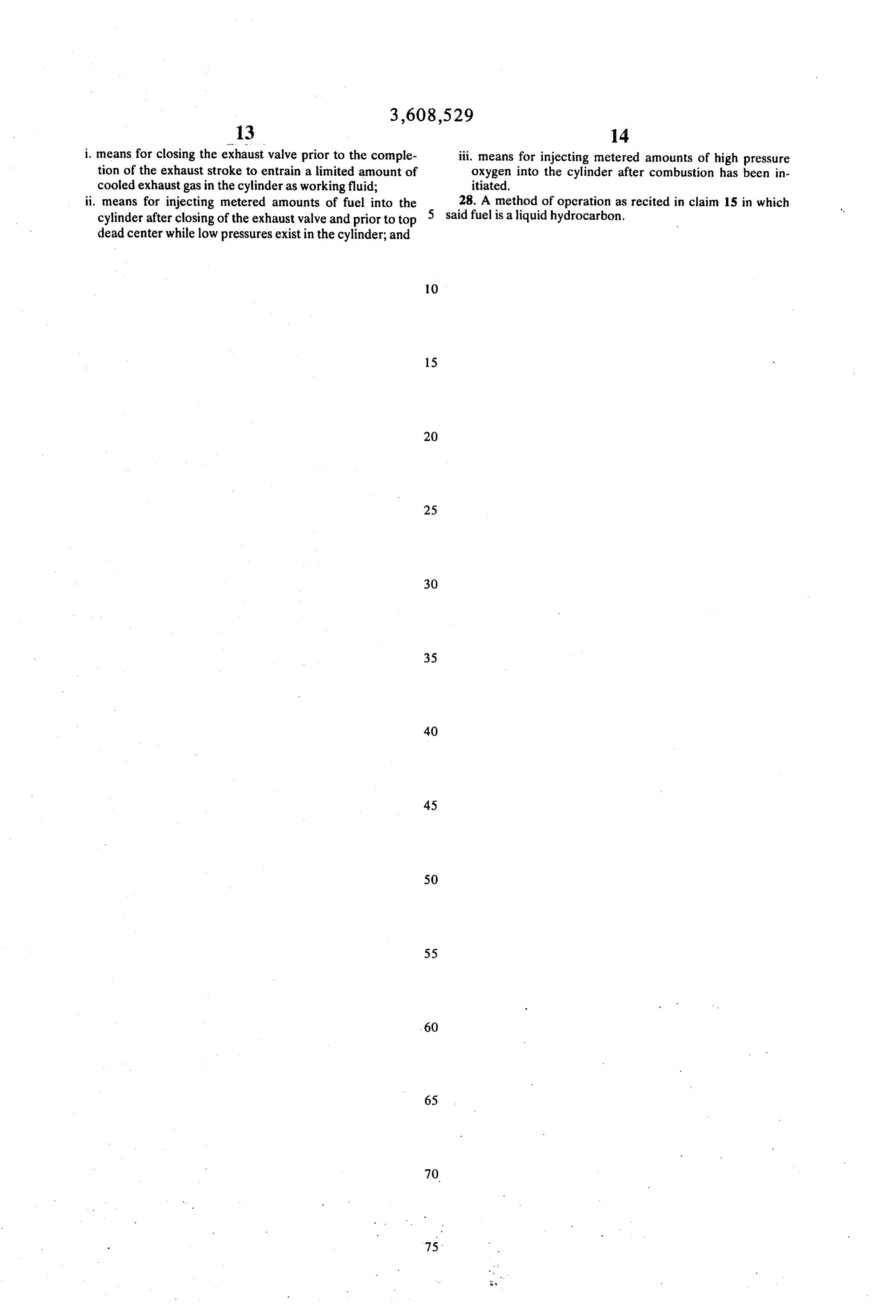
14. An engine, as recited in claim 12, in which said hydrogen gas fuel storage means comprises a set of intercon 65 i. means for closing the exhaust valve prior to the comple tion of the exhaust stroke to entrain a limited amount of nected storage tanks, means for supplying hydrogen gas from cooled exhaust gas in the cylinder as working fluid; said storage tanks to said fuel injector, said means for supply ii. means for injecting metered amounts of fuel into the ing said hydrogen gas including means for regulating the flow cylinder after closing of the exhaust valve and prior to top of said hydrogen gas through said supplying means. dead center while low pressures exist in the cylinder; and 15. A method for operating an internal combustion engine 70 iii. means for injecting metered amounts of high pressure having: oxygen into the cylinder after combustion has been in l, at least one cylinder; itiated.
2. a piston reciprocating in said cylinder; 27. An engine, as recited in claim 2 wherein said means for 3. an exhaust port in said cylinder; igniting the injected mixture is a spark plug, and further in 4. an exhaust valve in said port; 75 cluding:
Page 13
i. means for closing the exhaust valve prior to the comple- iii. means for injecting metered amounts of high pressure tion of the exhaust stroke to entrain a limited amount of oxygen into the cylinder after combustion has been in cooled exhaust gas in the cylinder as working fluid; itiated.
ii. means for injecting metered amounts of fuel into the 28. A method of operation as recited in claim 15 in which cylinder after closing of the exhaust valve and prior to top 5 said fuelis a liquid hydrocarbon, dead center while low pressures exist in the cylinder; and
Page 14
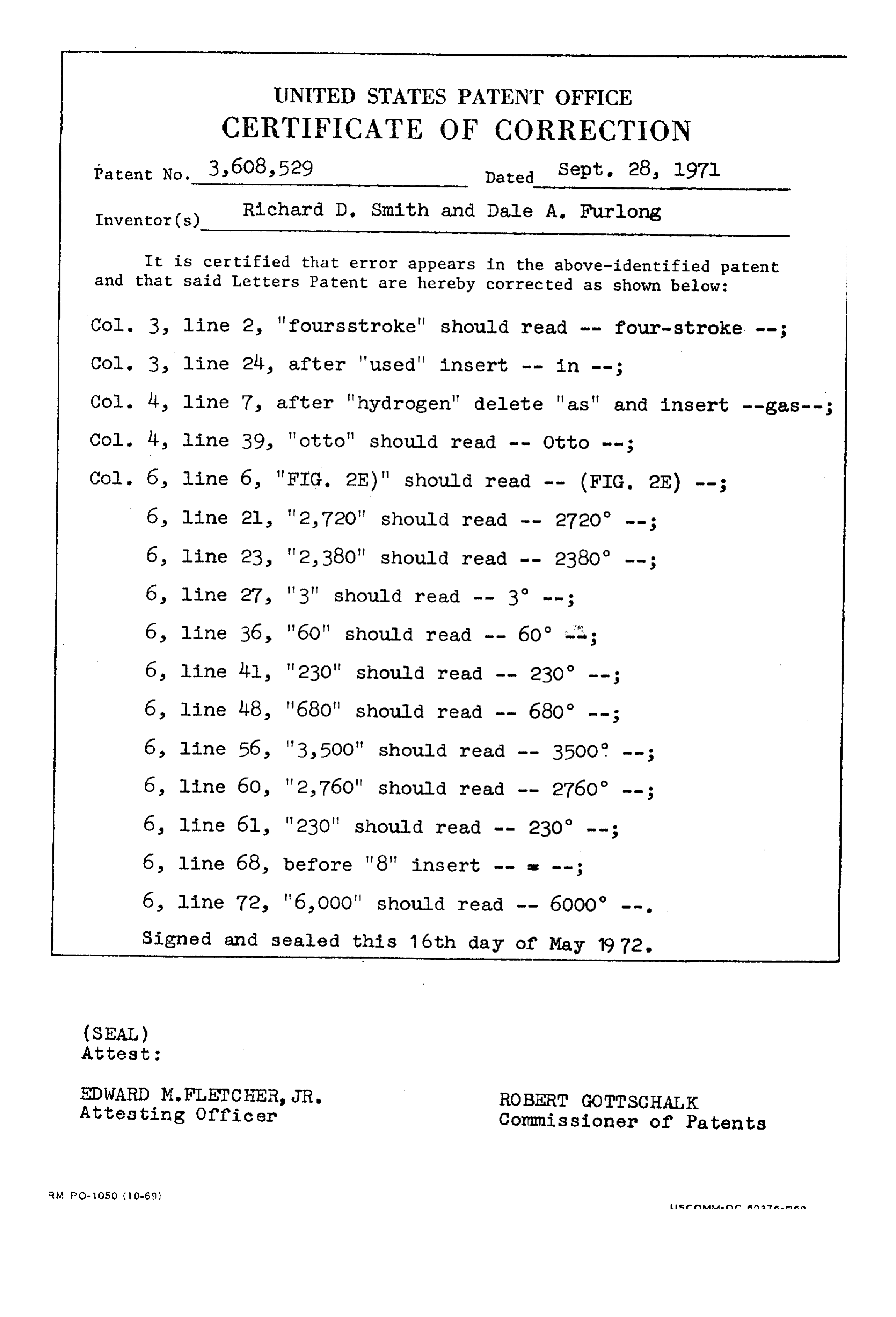
UNITED STATES PATENT OFFICE
CERTIFICATE OF CORRECTION
Patent No. 3,608,529 Dated Sept. 28, 197l Inventor(s) Richard D. Smith and Dale A. Furlong
It is certified that error appears in the above-identified patent and that said Letters Patent are hereby corrected as shown below: line 2, "fours stroke" should read -- four-stroke -- Col. 3, line 24, after "used' insert -- in --;
Col. 14, line 7, after "hydrogen" delete "as" and insert --gas--; Col. 4, line 39, 'otto" should read -- Otto --;
s line 68, before '8" insert -- as --;
Signed and sealed this 16th day of May 1972.
(SEAL)
Attest :
EDWARD M.FLETCHER, JR. ROBERT GOTTSCHALK Attesting Officer Commissioner of Patents
Provenance
- Collection
- Cited prior art
- Original PDF
- patentimages.storage.googleapis.com →
- Filed
- 1969-05-01
- Pages
- 14
- Method
- pdftotext (the PDF's own text layer) + pdftoppm 300dpi page scans
- Source
- Google Patents bibliographic record
- Granted
- 1971-09-28
- Inventors
- Richard D Smith; Dale A Furlong; Combustion Power Co Inc
- Transcribed from
- patentimages.storage.googleapis.com →