patent · US3862624
Oxygen-hydrogen fuel use for combustion engines
28 January 1975
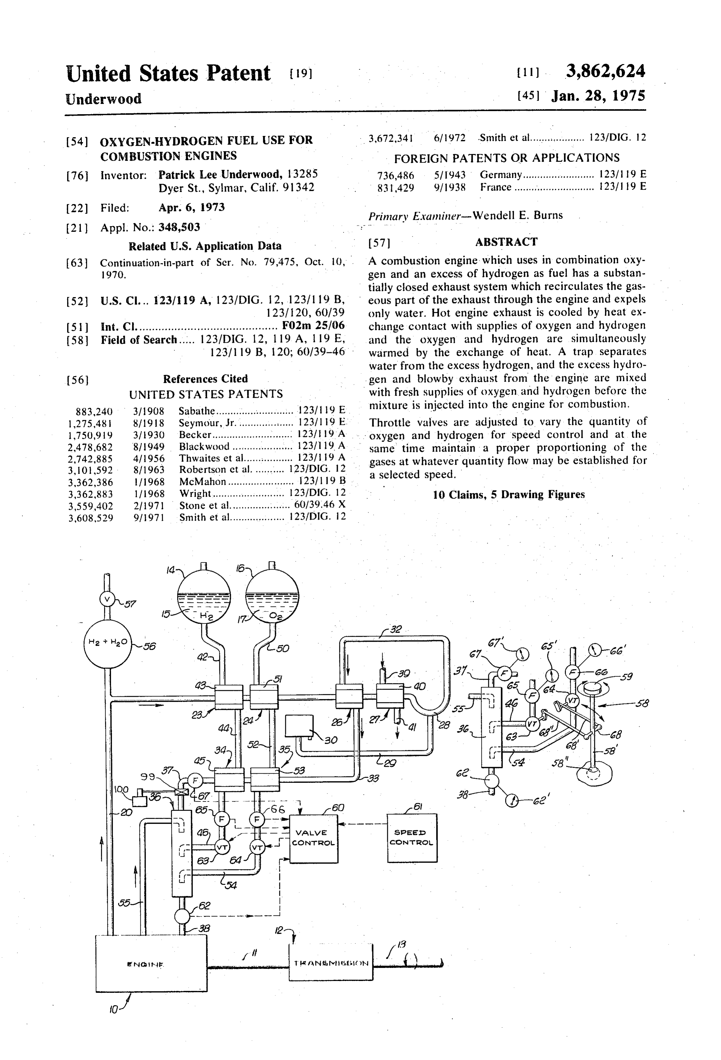
Page 1 — bibliographic record
United States Patent 19) (11). 3,862,624 Underwood (45) Jan. 28, 1975
54) OXYGEN-HYDROGEN FUEL USE FOR 3,672,341 6/1972 Smith et al.................. 123/DIG. 12 COMBUSTION ENGINES FOREIGN PATENTS OR APPLICATIONS 76 inventor: Patrick Lee Underwood, 13285 736,486 5/1943 Germany......................... 12311 19 E Dyer St., Sylmar, Calif. 91342 83,429 9/1938 France............................ 123/19 E
Primary Examiner-Wendell E. Burns (21) Appl. No.: 348,503 --- -
Related U.S. Application Data (57) ABSTRACT (63) Continuation-in-part of Ser. No. 79,475, Oct. 10, A combustion engine which uses in combination oxy 1970. gen and an excess of hydrogen as fuel has a substan tially closed exhaust system which recirculates the gas (52) U.S. Cl... 123/119 A, 123/DIG. 12, 123/119 B, eous part of the exhaust through the engine and expels 123/120, 60/39 only water. Hot engine exhaust is cooled by heat ex (5) int. Cl. ........................................... F02m 25/06 change contact with supplies of oxygen and hydrogen (58) Field of Search..... 123/DIG, 12, 19 A, 19E, and the oxygen and hydrogen are simultaneously 123/119 B, 120; 60/39–46 warmed by the exchange of heat. A trap separates water from the excess hydrogen, and the excess hydro 56 References Cited gen and blowby exhaust from the engine are mixed UNITED STATES PATENTS with fresh supplies of oxygen and hydrogen before the 883,240 3/1908 Sabathe.............. . . . . . . . . . . . . . 123/19 E mixture is injected into the engine for combustion. 1,275,481 8/1918 Seymour, Jr.................... 123/19 E. Throttle valves are adjusted to vary the quantity of 1,750,919 3/1930 Becker............ ... ... 123/19 A oxygen and hydrogen for speed control and at the
same time maintain a proper proportioning of the
3,101,592 - 8/1963 Robertson et al........... i2G2 y quantity flow may be established for 3,362,386 l/1968 McMahon....................... 123/19 b a selected speed.
3,362,883 1/1968 Wright......................... 23/DIG. 12 10 Claims, 5 Drawing Figures 3,559,402 2/1971 Stone et al.............. . . . . . . . 60/39.46 X 3,608,529 9/971 Smith et al................... 123/DIG. 12
if nant. frnwt.fm
Page 2
Drawing sheet — no readable text.
Page 3
Drawing sheet — no readable text.
Page 4
Drawing sheet — no readable text.
Page 5
OXYGEN-HYDROGEN FUELUSE FOR and carburetor and which, when fueled with hydrogen, COMBUSTION ENGINES avoids the formation of engine oil acid. Additionally included among the objects of the in
This is a continuation-in-part of the copending appli vention is to provide a new and improved fuel system cation, Ser. No. 79,475, filed Oct. 10, 1970. su 5 for a combustion engine wherein, by use of hydrogen and oxygeen in liquid state as a source of energy, makes
The object of the invention is to eliminate completely possible all pollutants from the system exhaust of a conventional employment of the system as a cooling expedi internal combustion engine without the necessity of ent to take the place of the conventional air modifying the basic engine design. . conditioning device, and provide a cooling air condi Exhaust pollutants from internal combustion engines 10 tioner for such vehicle as may be operated by use of the fueled by hydrocarbons and using air as an oxidizer system. - -
consist of fuels not fully oxidized, oxides of nitrogen, With these and other objects in view, the invention carbon monoxide and various chemicals formed in the consists in the construction, arrangement, and combi cylinder by reaction of the fuel additives with the oxy nation of the various parts of the device, whereby the gen and nitrogen of the air within the high presssure, 5 objects contemplated are attained, as hereinafter set high temperature and electric arc presence in the envi forth, pointed out in the appended claims and illus ronment of the normal otto cycle engine common to trated in the accompanying drawings.
current automotive propulsion systems. Although car In the drawings:
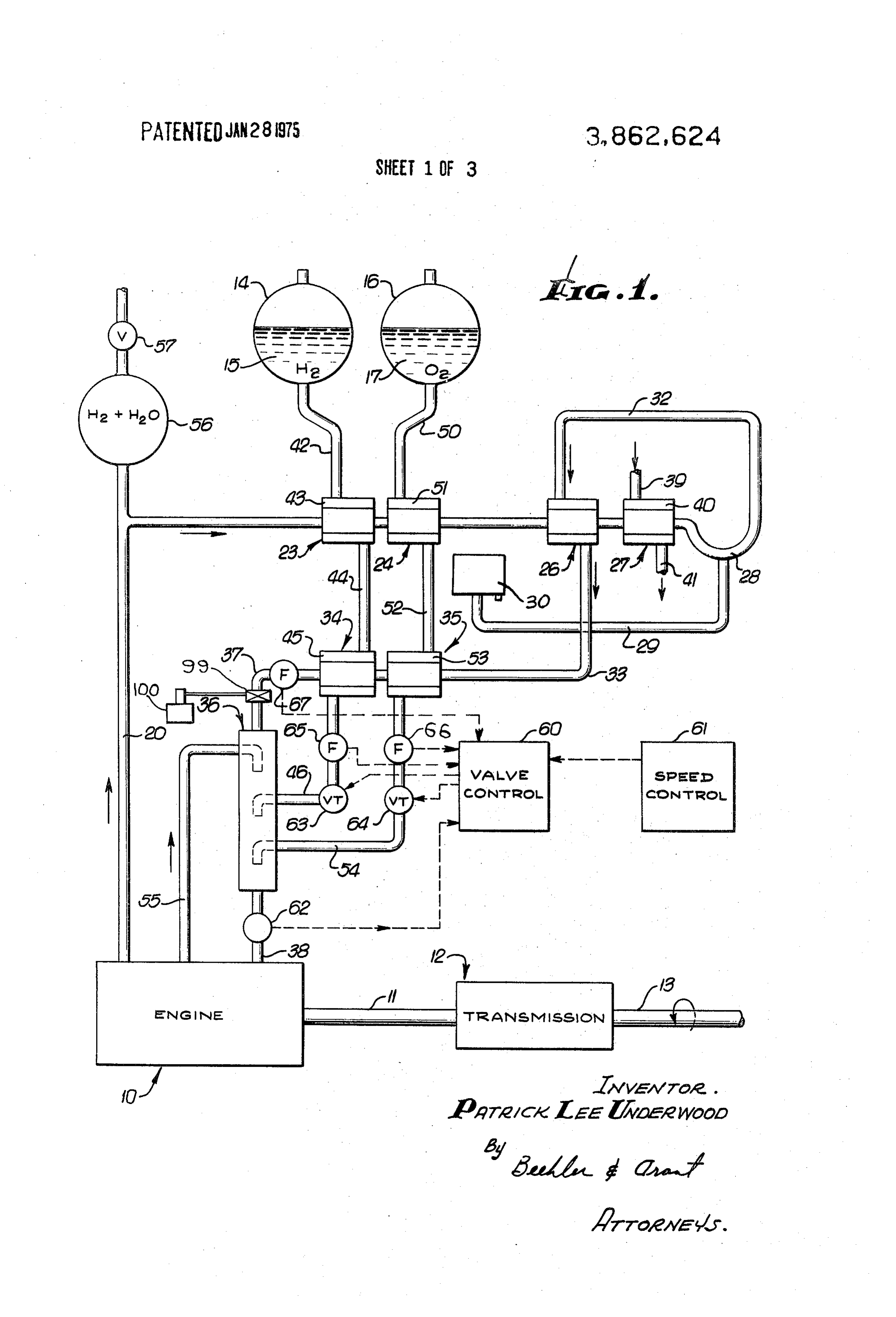
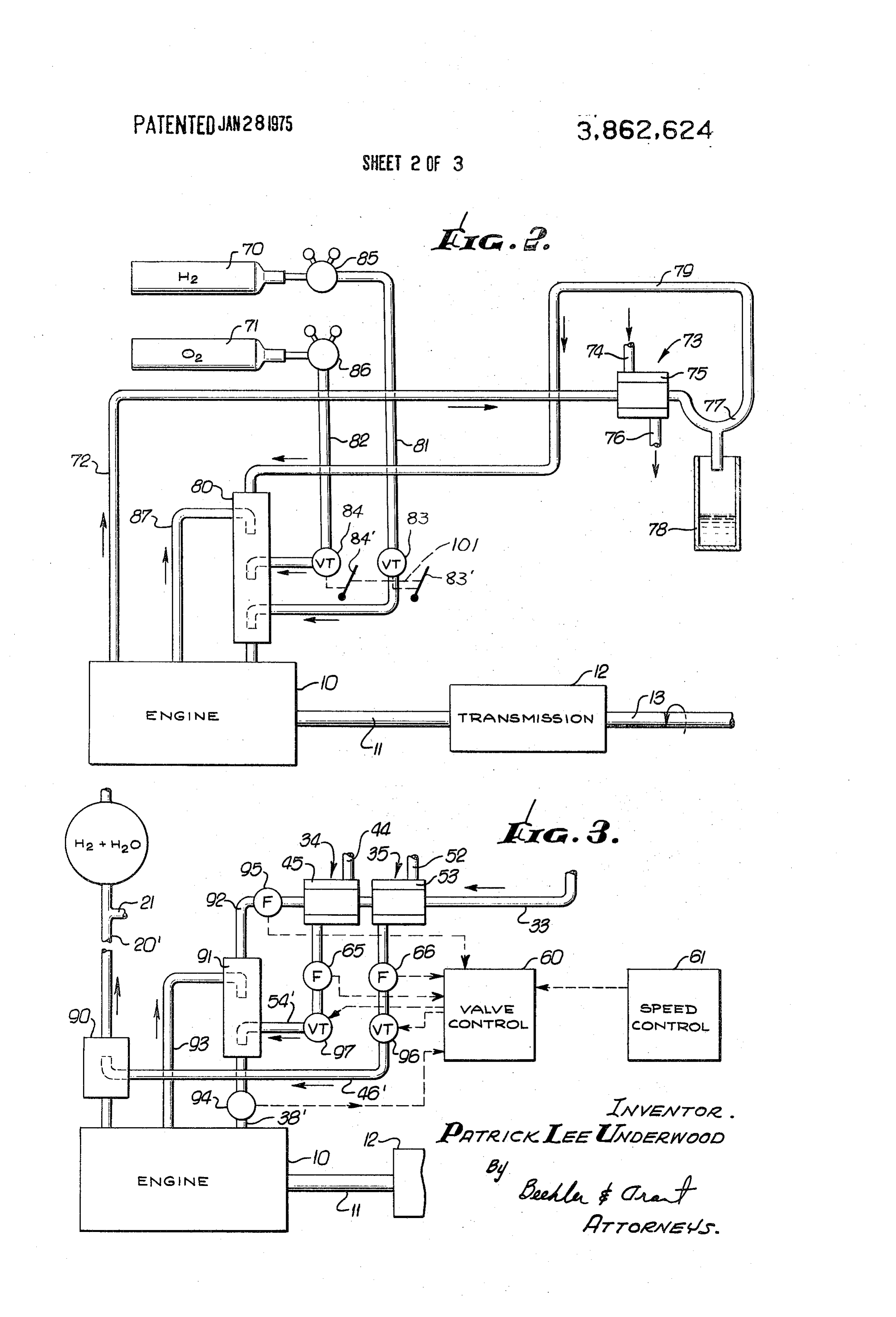
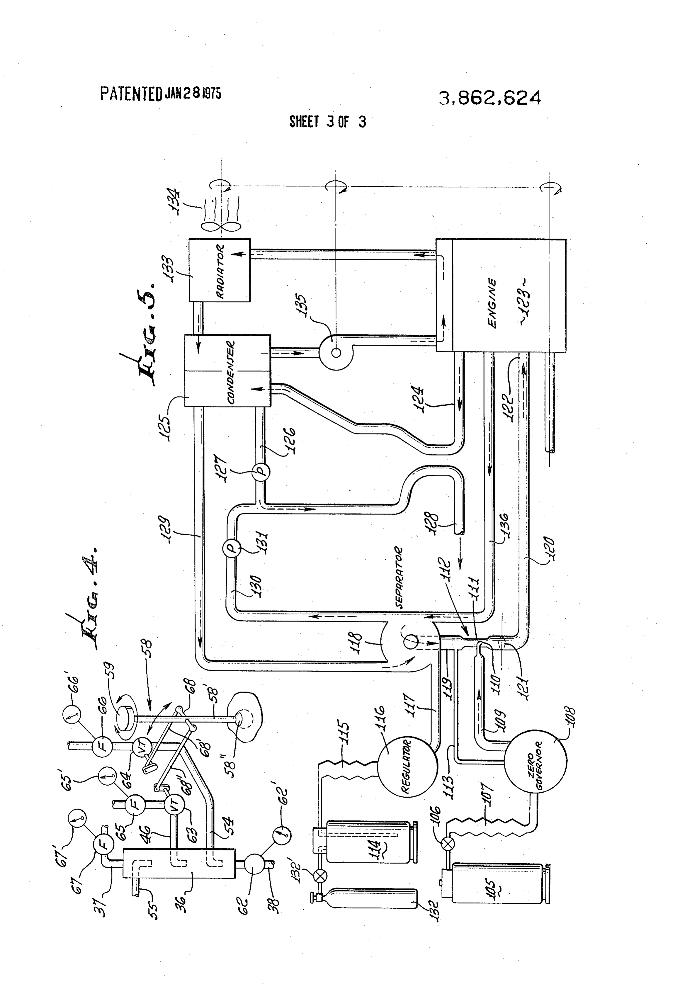
bon dioxide is produced by humans and animals, inter 20 FIG. 1 is a schematic representation of one form of nal combustion engines fueled by hydrocarbons pro the fuel system which contemplates employment of hy duce carbon dioxide at a sufficiently great rate to b drogen and oxygen in liquid state. considered a pollutant. Although some water is alsso FIG. 2 is a schematic representation of a second form produced by engines fueled by hydrocarbons water is of the invention which makes use of oxygen and hydro not generally considered a pollutant. gen as fuel in a compressed gaseous state. In the invention here disclosed, hydrogen and oxygen 25 FIG. 3 is a schematic representation of a somewhat are used as fuel so that water is the only product of modified form of the invention illustrated in FIG. 1. combustion and thus is not a pollutant by any defini FIG. 4 is a manual control for operation of all forms tion. In this example, removal of water is accomplished of the invention. . . . . by taking the engine exhaust, consisting of water vapor, 30 FIG. 5 is another form of the invention showing a dif hydrogen and miscellaneous inert gases and partially or ferent means for controlling engine speed. fully oxidized elements, and passing the mixture In one embodiment of the invention chosen for the through a condenser next to a separator to remove the purpose of illustration there is shown a substantially liquid water and then returning the remaining gaseous conventional combustion engine indicated generally by portion of the mixture to the intake manifold of the en 35 the reference character 10 which, acting through a gine. The separated water may be collected in a reser shaft 11 and transmission 12, is adapted to operate a voir, or may be exhausted from the system directly in drive shaft 13.
the liquid state. Fuel for the engine is contained in a reservoir 14 The miscellaneous returned gases are mixed with a adapted to contain a quantity 15 of liquid hydrogen and quantity of hydrogen sufficient to regulate the engine a reservoir 16 adapted to contain a quantity of liquid speed. The blowby gases from the engine crankcase, 40 oxygen 17.
consisting mostly of hydrogen but having some oxygen, Inasmuch as recirculation of the engine exhaust is an water vapor, lubricating oil vapor and miscellaneous important phase of the system attention is initially di other substances, and sufficient oxygen to oxidize an rected to an engine exhaust line 20 and its extension 21 amount of the hydrogen provided for engine speed con 45 which is served by a series of heat exchangers 23, 24, trol are added to the mixture. This mixture is then in 26, and 27 at the end of which is a water separating de troduced into the engine intake manifold for normal vice in the form of a trap 28. Inasmuch as the fuel for combustion and subsequent exhausting from the engine the engine is a mixture of oxygen and hydrogen the to complete the recirculation cycle. Miscellaneous principle ingredient of the exhaust is water which, in gases referred to in this foregoing description can be an . 50 view of the series of heat exchangers, has been con inert gaseous component, hydrogen only, oxides of ni verted to liquid and which, by operation of the trap 28, trogen, carbon dioxide, or other combination of gases is separated out passing through an exhaust liquid line suitable to retard the flame speed and to provide an ex 29 and deposited into a reservoir 30. pansion medium when the engine is not operating at Since the system is designed and adapted to operate full throttle. 55 with a surplus of a selected gaseous ingredient which is
Among the objects of the invention is to provide a part of the engine exhaust mixture, a surplus gas return new and improved fuel cycle for an internal combus 32 leading from the trap 28 passes through the outer tion engine which will substantially eliminate exhaust jacket of the heat exchanger 26 on its way to a pipe 33 of substances commonly identified as atmosphere pol and ultimately back to the engine 10. lutants. 60 More specifically the pipe 33 is directed through two Still another object of the invention is to provide a additional heat exchangers 34 and 35 and then enters new and improved fuel system for an internal combus a mixer 36 by way of a pipe 37. An intake manifold 38 tion engine in which the only exhausted component is receives fuel gas from a pipe 38' at the outlet of the Water. mixer and passes it to the engine 10. Still another object of the invention is to provide a 65 The heat exchanger 27, serving as a condenser and new and improved fuel system for an internal combus previously identified as being located in the extension tion engine which improves the quietness of operation 21 of the exhaust line, may be a substantially conven of the engine, which eliminates the need for muffler tional heat exchanger such for example as a radiator of
Page 6
the type commonly used on automotive vehicles, capa As operation of the circuit progresses the engine ex ble of circulating cooling water through an inlet 39 and haust is partially cooled by action of the heat exchang then around a jacket 40 to an outlet 41. ers 23, 24, and 26 before reaching the heat exchanger Since liquid hydrogen and liquid oxygen respectively 27 and the trap 28, the trap 28 being designed to pre in the reservoirs 14 and 16 tend to emerge in cold con- 5 vent those excape of the surplus gas from the system. On occasions where the surplus gas is hydrogen the dition from the reservoirs, it is desirable to warm these fuels before they reach the mixer 36 and are injected trap will separate hydrogen into the water which is the into the engine. To accomplish this, a pipe 42 from the product of the combination of two parts hydrogen and oxygen reservoir 14 communicates with a jacket 43 of to operateoxygen one part the made use of as the explosive mixture engine.
the heat exchanger 23 and is warmed by the heat of the 10 A substantial excess of hydrogen is made use of engine exhaust. A pipe 44 from the jacket 43 communi which may be ninety-two parts by volume over and cates with a jacket 45 of the heat exchanger 34 where above the the hydrogen is warmed additionally by heat which re tion. Whenquantity of hydrogen necessary for combus mains present in the surplus gas returning through pipe ple is surplus hydrogen,gas,passes the surplus which in the present exam through the heat ex 33, action of the heat exchangers 23 and 34 thereby 15 changers 34 and 35, the surplus gas serving to convert liquid hydrogen into gaseous hydro substantially the temperature of thewill be brought to gen before it passes through a supply pipe 46 to the which in the present example is hydrogen and fuel oxidizer and oxygen, mixer 36.
Similarly, a pipe 50 from the oxygen reservoir 16 before all, by their separate supply pipes, are passed to passes liquid oxygen to a jacket 51 of the heat ex- 20 theThe mixer 36.
changer 24 from which is flows through a pipe 52, con providepurpose of the flow meters 65, 66, and 67 is to verted into gaseous form, to a jacket 53 of the heat ex proper net volumetricto supply information the valve control 60 to maintain changer 35. From the jacket 34 oxygen passes through drogen to one part of oxygen ratio for of two parts of hy proper combustion.
a supply pipe 54 on its way to the mixer 36 and ulti During the acceleration mode, excess hydrogen and
To complete the circuit there is provided a blowby water vapor are stored in the accumulator 56 until con exhaust line. 55 which accepts exhaust from the crank stant speed is reached, or the deceleration mode has started. The relief valve 57 will vent excess pressures.
case of the engine and passes it to the mixer 36. It fol developed in the accumulator by system operation as lows therefore that the mixer 36 receives gaseous com has been previously noted. ponents from several different sources, namely the 30 As an example of manual control of the quantity of blowby exhaust, the surplus gas return, and the fresh oxygen and hydrogen to the manifold to change engine fuel supplies of oxygen and hydrogen wherein all are speed reference is made to FIG, 4. As there shown a mixed before being returned to the inlet side of the battery of indicators reveal visually the flow conditions combustion engine. 35 at various locations at any given instant. An indicator In the engine exhaust line 20 is an accummulator 56 equipped with a relief valve 57 to prevent over 67' is connected to the flow meter 67, an indicator 65 pressuring of the system. to the flow meter 65 and an indicator 66 to the flow Because of inherent differences in flow rates of hy use meter 66. Where further flow information can be made drogen and oxygen upon changes in demand, it is ad 40 the pressureof an indicator 62' may be provided connected to vantageous to make use of an automatic valve control gage 62.
A speed 60 responsive jointly to a speed control 61 and a pres a universal mountingcontrol throttle lever 58 has an arm 58 on sure gauge 62 at the intake manifold in controlling 50'. A cross bar 68 has one end throttle valves 63 and 64 respectively in the hydrogen attached to a link 68' for manipulation of the throttle supply pipe 46 and oxygen supply pipe 54, thereby to 45 valve 64 for oxygen and the other end attached to a link control the quantity of oxygen fuel and make up hydro gen. 68' for manipulation of the throttle valve 63 for hydro gen being introduced to the mixer 36 and, in conse wardly A handle 59 on the arm 58' may be thrown fore or rearwardly to open or close both throttle quence, to control the speed of the engine. The speed valves simultaneously control may, if desired, be entirely manual. thereby to alter the speed of the Flow meters 63 and 64 respectively in the same hy 50 engine. At the same time the handle 59 may be rotated drogen supply line 46 and oxygen supply line 54 are to vary the relative openings or closings of the throttle connected respectively to the automatic valve control valves.Because of the different molecular weights of oxygen 60. A flow meter 67 in the pipe 37 returning surplus gas and hydrogen, flow rates vary with respect to each to the mixer 36 is similarly connected. other depending on demand for quantity of the respec The flow meters 65, 66, and 67, of conventional con 55 tive gases. Hence for higher speeds, by way of example, struction, provide the valve control with information a greater quantity of both gases will be needed but at indicating the rate of flow in the respective pipes. Re the proportionate quantities lated information is provided by the pressure gauge 62 The proportion must remain atofafreshly supplied gases. to the flow meter giving pressure at the intake mani gen to one part hydrogen as delivered two ratio of
parts oxy the intake fold. By a conventional integrating system, not part of 6O the present invention, the valve control 60, when acti manifold 38. Because of the fact that when subject to greater demand the flow rates vary, the amount of vated by the speed control 61 at the volition of the op opening erator, mechanically operates the flow controls 63 and amount ofofopening the control throttle 63 relative to the 64 in either an opening direction for speed up of the be changed slightly.in the control throttle 64 needs to system or in a closing direction for lessening speed. 65 As a guide to the operator in adjusting the manual Equivalent operation can be achieved by manual ma settings the indicators 66', 65' and 67' respectively nipulation of the flow controls directly by the speed constantly supply a visable indication of flow in the ox
Page 7
ygen and hydrogen in the supply lines 52 and 44 re flow control 60 in FIG. 1, or by the manual control of spectively, and also flow in the surplus gas return line FIG. 4. . . - 37. As a safety feature the indicator 62' shows the flow In the form of device of FIG.3 oxygen, after passing condition at the manifold at a point where all gaseous through the customary heat exchangers shown in con components have been combined. This is a warning as 5 nection with FIG. 1, is fed to the modified mixer 91 to how rapidly or slowly changes in quantity flow, and from an oxygen supply pipe 54'.
accordingly speed control, should be made. A flow meter 95 in the pipe 92 serves a purpose simi Although an additional surplus gas such as argon or lar to that described for the flow meter 67 in FIG. 1. one of the other suggested gases may be introduced ini Throttle valves 96 and 97 respectively for hydrogen tially into the system the selected surplus gas or surplus 10 and oxygen, working through a valve control like the gas of any selected kind to the system may be added valve 1 control 60 of FIG. 1 and speed control 61 of FIG.
serve to control the quantities of hydrogen and oxy later.
Exhaust circuit illustrated in FIG. 2 a somewhat dif gen respectively fed to the engine and thereby control ferent arrangement is illustrated consisting of fewer the speed.
components but in which the fuel hydrogen and oxi 15 Although an excess of hydrogen has been used in the dizer oxygen are stored respectively in pressure cylin description of the circuit and its operation, it should be ders 70 and 71 in the compressed gas state. An engine understood that the surplus gas may be some other gas exhaust line 72 conducts gaseous engine exhaust to a eous ingredient such as one of the inert gases like argon heat exchanger 73, operating on substantially conven or a mixture of such gaseous elements. Under some cir tional principles to cool the exhaust gases by a cooling 20 cumstances air may be used as the surplus gas, or some liquid flowing from an inlet 74 to a jacket 75, and, other gas which will not take part in the oxygen thence, outwardly through an outlet 76. The cooling hydrogen combustion. To make it possible to inject sur effect is made sufficient such that be the cooled ex plus gas of any kind, there may be provided in the pipe haust gases reach a trap also the resulting water is sepa 25 37 a conventional three-way valve 99 supplied by a container 100 which contains the desired additional rated out and dumped into a receiver 78 and the re maining surplus gas, passes through a surplus gas return surplus gas. - Proportions of the surplus gas may vary, line 79 for ultimate delivery to the combustion engine. amples productive of acceptable results being as foltypical ex A mixer 80 receives the surplus gas from the surplus gas return line 79 and also receives hydrogen from the 30 lows:
hydrogen supply line 81 and oxidizer namely oxygen from an oxygen supply line 82. The flow of hydrogen Example 1: Oxygen 20% is controlled by means of a manual throttle valve 83 Example 2:
Hydrogen 80%
Oxygen 4% manipulated by a lever 83', oxygen being controlled by Hydrogen 96% means of a manual throttle valve 84 manipulated by a 35 - Example 3: Oxygen 8% lever 84', before being passed to the mixer 80. A hy Hydrogen 92% drogen pressure regulator 85 controls hydrogen pres sure to the supply line 81 and an oxygen pressure regu The invention in the form illustrated in FIG. 5 exem lator 86 controls oxygen pressure to the supply line 82. plifies an alternative expedient for introducing oxygen To complete the recirculation cycle a blowby exhaust under control to the system at a location such that the line 87 takes exhaust from the engine crankcase and 40 speed control of a standard internal combustion engine passes it to the mixer 80. can be governed by a simple butterfly valve. Oxygen and hydrogen in this form of the circuit being The system embodies a container 105 of liquid oxy initially supplied as gases serve to minimize need for gen held preferably under a pressure of 80 pounds per the numerous heat exchangers described in connection 45 square inch. Oxygen from the container passes to a with the FIG. 1 circuit and the engine speed can there conventional regulator 106 where the pressure is low fore be more directly controlled by the throttle valves ered to a pressure of 10 pounds per square inch at 70 83 and 84 linked in a conventional manner by linkage Farenheit. From here the oxygen passes through a va 101 which, in the event that the engine is an automo porizer 107 and then to a governor 108. From the gov tive engine, would be the driver of the vehicle. 50 ernor oxygen passes through a supply line 109 to an as
In still another modified form of the circuit as illus pirator 110 at the throat 111 of a venturi 112. A pres trated in FIG. 3 hydrogen from the hydrogen supply sure reference line 113 provides a connection from the pipe 46' is conducted to an injector 90 in an engine ex intake side of the venturi 112 to the governor 108. haust line 20' in a manner such that hydrogen gas as In this form of the invention by way of example hy fuel first flows from the engine exhaust line 20' to the 55 drogen in liquid form is supplied from a container 114 extension 21 and thence through all of the heat exhang at1510and pounds per square inch pressure to a vaporizer then to a regulator 116. The purpose of the ers 23, 24, 26, and 27 before passing into the engine in take manifold 38' from a modified mixer 91 by way of regulator is merely to be certain that the oxygen is at a pipe 92. a pressure of about one-fourth pound per square inch As previously described in connection with the forms 60 higher passes than ambient. From the regulator hydrogen through a hydrogen supply line 117 to a separa of invention of both FIG. 1 and 2, blowby exhaust passes through a blowby exhaust line 93 to the modi the tor 118, from which a pipe 119 passes the hydrogen to fied mixer 9 where it mixes with the fuel gas, the oxi entrance end of the venturi 112. Hydrogen mixing dizer, and the surplus gas before being passed through with oxygen in the throat of the venturi in a stoichio a flow meter 94 to the intake manifold 38' an thence 65 metric ratio passes to the outlet end of the venturi and to the engine 10. then through a combined conduit 120 in which is lo The flow meter 94 in the form of FIG. 3 is adapted cated a conventional speed control of the butterfly type to be controlled by the flow control 60, similar to the 121. From the conduit 120 the gaseous mixture flows
Page 8
to an intake 122 of a conventional combustion engine times
what may aply be described as a super abundance surplus of hydrogen gas, or possibly hydrogen mixed 123. with some other inert gas, this surplus always being A conventional engine exhaust is exemplified by a combined passageway 124 from which the exhaust, 5 present throughout the system except in the supply lines of fuel oxygen and fuel hydrogen.
which is a mixture of water in either steam or moist condition together with surplus hydrogen travels to a In all forms of the invention operation is begun in a condenser 125 where the water is separated from the substantially conventional fashion by cranking the en surplus hydrogen. Water is drawn through a pipe 26 gine thereby to create sufficient suction to draw the by pump 127 and then passed through a discharge line O combustion fuel into the system where ignition is ef.
128 to atmosphere. fected by spark plugs.
The surplus hydrogen, which is in appreciable vol While the invention has herein been shown and de ume, passes from the condenser 125 through a pipe scribed in what is conceived to be a practical and effec 129 to the separator i 18. The function of the separator tive embodiment, it is recognized that departures may is merely to extract any water which may remain pres be made therefrom within the scope of the invention, ent in the surplus hydrogen, such water as may be ex which is not to be limited to the details disclosed herein tracted being discharged through a pipe 130 by means but is to be accorded the full scope of the claims so as of a pump 131 and from there passed to the discharge to embrace any and all equivalent devices. line 128 where it joins the water initially separated out Having described the invention, what is claimed as by the condenser 125. new in support of Letters Patent is: The surplus hydrogen from which the water has been 1. In a piston and cylinder type combustion engine of extracted by the separator 118 passes to the pipe 119 the open cycle type having a conventional combustion which also receives fuel hydrogen from the hydrogen stage intake and exhaust valving and a crankcase and container 14. including a combustion chamber, a fuel system com To assist in discharging the hydrogen at the desired prising an engine fuel intake including a mixing passage rate use may be made of a container 132 containing 25 and conduit means from said mixing passage to said hellium at a storage pressure of 2,000 pounds per combustion chamber, open exhaust means from the en square inch which, when passing through a conven gine including said exhaust valving, a first source of gas tional regulator 132' is used to displace hydrogen in the comprising oxygen as fuel, a second source of gas com hydrogen container 14, the hellium taking no part in prising hydrogen as fuel, a supply line from the first the reaction nor in the system otherwise. source of gas to the mixing passage, a supply line from For operating the condenser 25 use is made of a the second source of gas to the mixing passage, the conventional automobile radiator 133 from which a fan 134 draws air, a coolant pump 35 circulates coolant quantity of gas of the type supplied from said second which may be water, over the condenser 125 to con 35 source cent when in said mixing passage at a location adja said conduit means therefrom being a surplus sev dense out the water as previously noted. The surplus coolant merely passes to the combustion engine for eral times greater than the quantity of the gas from the cooling in a purely conventional fashion. first source of gas which is productive of a stoichiomet Crankcase blowby vapors are carried through a ric ratio with said gas from the first source of gas, a por blowby exhaust line 136 to the separator 118 and the 40 tion of the exhaust means from the engine comprising blowby gas joins the surplus hydrogen as it emerges a combined passageway for surplus gas and water vapor from the separator and as it is joined by the fuel hydro from the engine, a water separating device in said pas gen as previously described. Should there be any water sageway adapted to separate water of combustion from vapor present in the blowby gases such water can be said surplus gas and including a discharge means for separated from the gases by operation of the separator 45 water open to the atmosphere, a heat exchanger in said 118. combined passageway on the upstream side of said Basically, the system of FIG. 5 operates in substan water separating device, and a gas return line for said tially the same fashion as has been described for FIG. surplus gas leading from said water separating device to 1 and the other forms of the invention. The expedient said mixing passage whereby to maintain a surplus of resorted to embodied in the venturi principle is one 50 said gas from said second source of gas in the engine at only of a variety of ways which can be employed to the combustion stage.
maintain a stoichiometric ratio of fuel oxygen and fuel 2. A fuel system as in claim 1 including a heat ex hydrogen at different rates of flow, such rates being the changer in said gas return line for said surplus gas at a result of manipulation of the speed control butterfly location between said mixing chamber and said sepa valve 121. It should be borne in mind that the principle 55 of operation of the system namely maintenance of a rating device.
3. A fuel system as in claim 1 wherein said exhaust super abundance of hydrogen as an excess gas is the means comprises one line communicating between said principle of operation of the system of FIG. 5 as it is engine, said separating device and said mixing chamber with the other systems, blowby is retained in the system and another line communicating between the crank as a closed system so that the only waste product of the 60 case of said engine and said mixing chamber. system is water which is a non-atmospheric pollutant. 4. A fuel system as in claim 1 wherein said oxygen No special tailpipe is needed since the exhaust is not fuel supply and said hydrogen fuel supply are in liquid toxic. No muffler is needed because the exhaust sound form.
level is low resulting in little more than a slight rushing 5. A fuel system as in claim 1 wherein the surplus gas sound. 65 is hydrogen.
Although a stoichiometric ratio is mentioned for in 6. A fuel system as in claim 1 wherein the surplus gas troduction of fuel oxygen and fuel hydrogen, the salient includes a substantially noble inert gas. feature of the system is there being maintained at all
Page 9
7. A fuel system as in claim 1 wherein there is a heat derived from said separating device and said exhaust exchanger between the gas separated by said separating means, and between said surplus gas derived from said device and said exhaust means. separating device and said oxygen and hydrogen supply 8. A fuel system as in claim 1 wherein there is a heat lines. w exchanger between the gas separated by said separating 5 10. A fuel system as in claim 1 wherein there is an ac device and the supplies of oxygen and hydrogen fuel. cumulator having a relief valve therefore in communi 9. A fuel system as in claim 1 wherein there are heat cation with said exhaust means. exchangers between said exhaust means and said oxy xk xz k k k gen and hydrogen supply lines between said surplus gas
Provenance
- Collection
- Cited prior art
- Original PDF
- patentimages.storage.googleapis.com →
- Filed
- 1973-04-06
- Pages
- 9
- Method
- pdftotext (the PDF's own text layer) + pdftoppm 300dpi page scans
- Source
- Google Patents bibliographic record
- Granted
- 1975-01-28
- Inventors
- Patrick Lee Underwood
- Transcribed from
- patentimages.storage.googleapis.com →