patent · US3951129
Solar energy absorber
20 April 1976
Page 1 — bibliographic record
United States Patent 19 (11) 3,951,129 Brantley, Jr. (45) Apr. 20, 1976 (54) SOLAR ENERGY ABSORBER 3,815,574. 6/1974 Gaydos, Jr.......................... 126/27 | (75) lnventor: Lott W. Brantley, Jr., Union Grove,
Ala. Primary Examiner-Kenneth W. Sprague 73 Assignee: The United States of America as Assistant Examiner-James C. Yeung Attorney, Agent, or Firm-Wayland H. Riggins; L. D.
represented by the United States Wofford, Jr.; John R. Manning
National Aeronautics and Space
Administration, Washington, D.C. 57 ABSTRACT 22 Filed; Oct. 29, 1974 A solar energy absorber including a tubular absorber 21 Appl. No.: 518,684 surface through which a fluid passes for transferring thermal energy from the absorber to other devices.
52 U.S. C. ................................................ 126/27 Positioned above the tubular absorber surface are a (51 int. Cl.'............................................. F24, 3/02 plurality of spaced glass layers. Positioned between an 58 Field of Search............ 126/270, 271; 237/1 A; upper layer and the next layer is vacuum or air for 350,179, 312 minimizing thermal energy losses through convection.
A clear liquid passes between two intermediate layers 56 References Cited of glass for transferring by means of conduction the UNITED STATES PATENTS thermal energy absorbed therein by either the initial passage of the visible spectrum of electromagnetic 1093,925 4f 914 Foresman........................... 126/271 rays or by infrared radiation radiated from an ab 1,599,48 9/1926 Marcuse ....... ... 126/27 sorber positioned therebelow, 1,704, 73 3/1929 Chesney..... ... 126/27 | 2,783,682 3f 1957 Swenson ............................. 126/27 3 Claims, 2 Drawing Figures
NCOMING
RADATION
REFLECTED
RADATON
AAAs
Page 2
Drawing sheet — no readable text.
Page 3
Drawing sheet — no readable text.
Page 4
passed for removing thermal energy for subsequent use
SOLAR ENERGY ABSORBER so as to minimize thermal energy losses in the system. ORIGIN OF THE INVENTION Still another important object of the present inven tion is to provide a solar energy absorber which in
The invention described herein was made by an em cludes a plurality of spaced transparent plates with an ployee of the United States Government and may be energy removal medium to reduce the temperature manufactured and used by or for the Government for difference between the outer glass plate and the adja governmental purposes without the payment of any cent glass plate so as to minimize thermal losses. royalties thereon or therefor. Another important object of the present invention is () to provide a simple and efficient solar energy absorbing
BACKGROUND OF THE INVENTION device.
This invention relates to a solar energy absorber and These and other objects of the invention will become more particularly to using multiple glass layers for re more apparent from reading the following specification ducing the heat loss through re-radiation from the heat 5 and attendant claims. .
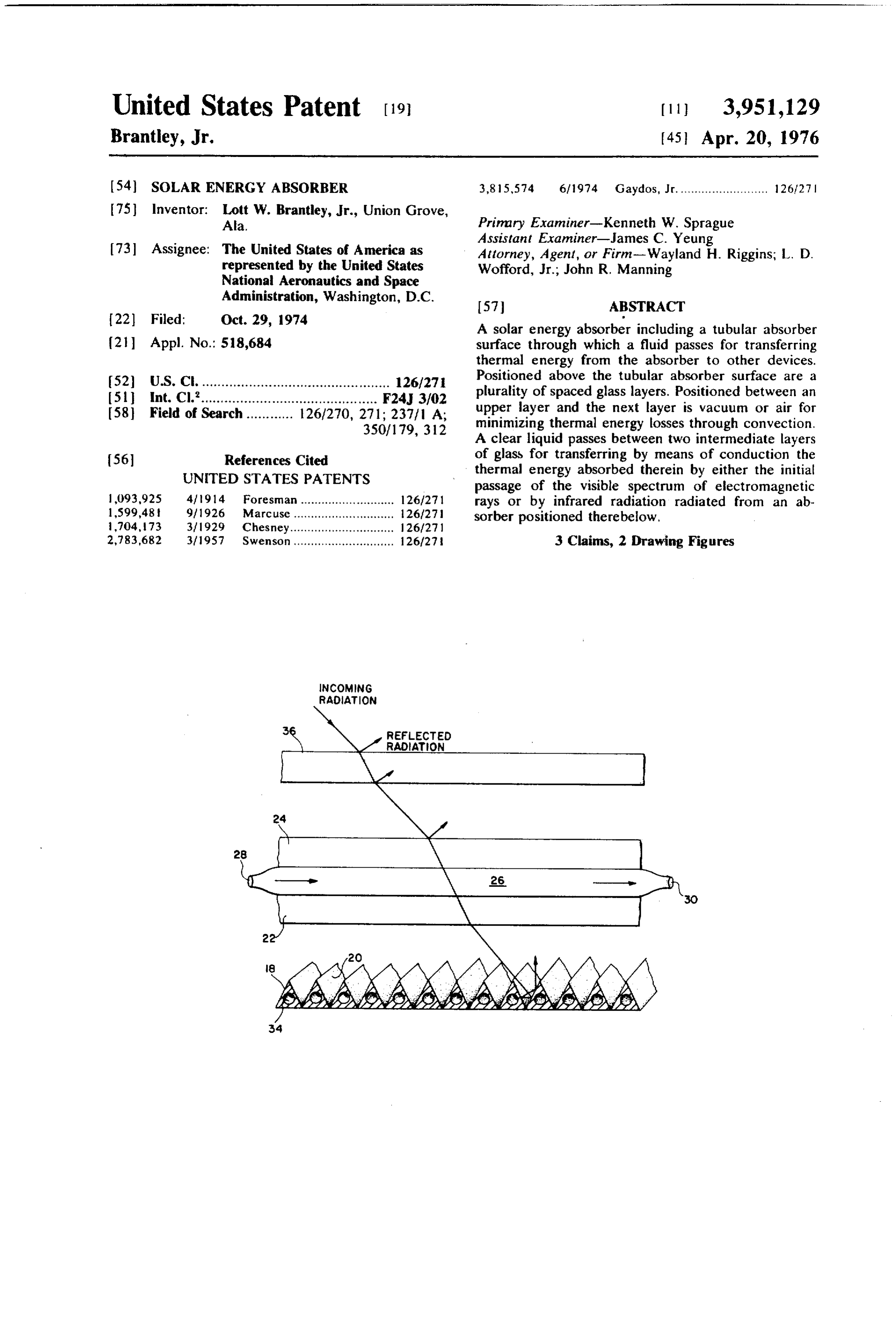
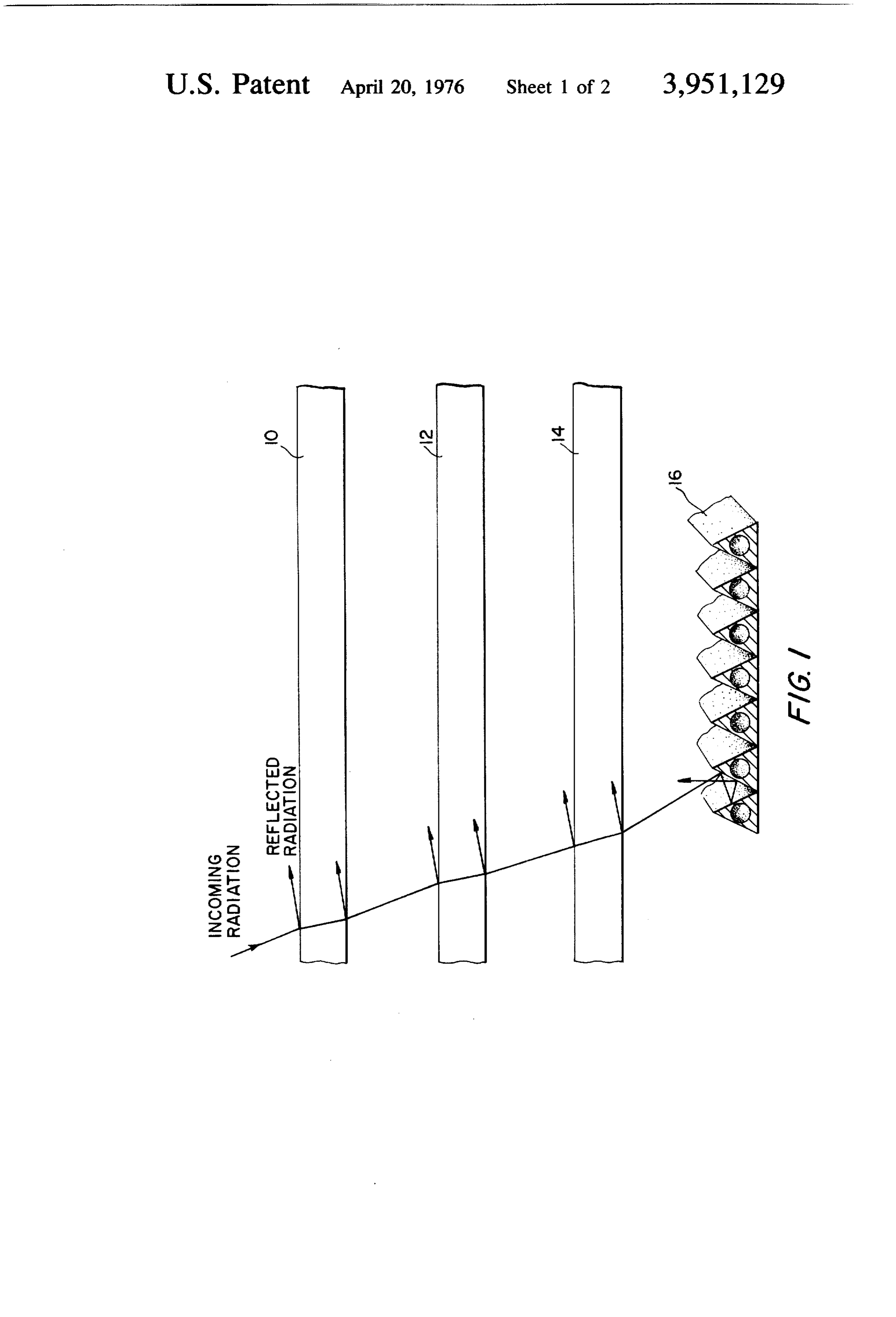
absorbing surfaces by circulating a heat conducting BRIEF DESCRIPTION OF THE DRAWINGS fluid between intermediate layers of glass to carry away the re-radiation heat. FIG. 1 of the drawings is a schematic diagram illus Heretofore, most systems designed to trap solar en trating a conventional solar energy absorber, and ergy utilized a system often called “the green house FIG. 2 is a schematic diagram illustrating a solar effect'. In such systems, visible radiation passes energy absorber in accordance with this invention. through one or more transparent outer covers and is DESCRIPTION OF THE PREFERRED almost entirely absorbed by an absorptive surface. The EMBODIMENT absorptive surface was usually constructed of tubing wherein a fluid must pass therethrough for transferring Referring in more detail to FIG. 1 of the drawings, thermal energy absorbed by conduction. The outer there is illustrated a portion of a conventional solar cover, while transparent to visible radiation is largely energy absorber. The solar energy absorber includes opaque to infrared radiation off of the absorber sur three glass plates 10, 12 and 14 stucked one above the face, and hence, absorhs it. lt conducts the energy that other with a vacuum or air layer carried therebetween. Directly below the lower glass plate 14 and spaced is not re-radiated to the absorber surface through the therefrom outer cover where it is convected or re-radiated away. is an absorber member 16. The absorber Examples of such a system are shown in U.S. Pat. No. member 16 may be constructed of triangular shaped 3,077, 19() and U.S. Pat. No. 2,969,788. tubing coated to absorb the visible spectrum of electro For a given absorptive surface, the amount of ther magnetic radiation. Fluid passes through the tubular mal energy lost by convection or re-radiation is a func sorbedmember 16 for transferring the thermal energy uh tion of the outer cover temperature. Often more than thereby. One problem with the solar energy one outer cover is used to reduce the infrared energy trum absorber shown in FIG. 1 is that since the visible spec reaching and, consequently, heating the final cover. of the electromagnetic waves have to pass through the three layers of glass, 10, 12 and 14, a cer
SUMMARY OF THE INVENTION tain amount thereof is reflected affecting the efficiency It has been found, in accordance with the present of the overall system. Another problem with the system invention, that an effective solar energy absorber can 12 andas14,thea energy is that passes through the glass layers 10, certain amount of the energy is absorbed be constructed which reduces the heat loss through also affecting the efficiency of the system. When dust re-radiation from the absorber surface. The apparatus includes a tubular absorber with a triangular surface iscollects on the glass layers 10, 12 and 4 this problem enhanced.
which has a surface coating thereon having a high radi Theoretically, in the device shown in FIG. 1, addi ation absorption factor (a ) for absorbing the visible tional spectrum of the electromagnetic energy emitted by the so as toglass layers could be stacked one above the other minimize the amount of infrared radiation loss.
sun and a low thermal emittance factor (e). Positioned However, as additional layers are added, such cuts between the outside atmosphere and the tubular ab down on the amount of the visible spectrum of electro sorber is a plurality of spaced glass plates for transmit magnetic radiation passing therethrough to reach the ting the visible spectrum to the absorber and for trap ultimate solar energy absorber. ping between the spaces of the glass plates heat or Referring in more detail to FIG. 2 of the drawings, thermal energy from the infrared radiation which is there is illustrated, in accordance with this invention, re-radiated from the tubular absorber. Between the 55 an first and second plates of glass a fluid is circulated for tubular member 18. constructed absorber surface of a triangular shaped
The tubular absorber 18 of FIG 2 removing the heat from the glass plates so as to reduce is shown schematically and the adjacent layers thereof the heat loss from the absorber. Either a separate fluid communicate or the same fluid is conveyed in heat exchange relation ration whetherwith each other and the overall configu circular, rectangular, etc. depends on ship with the tubular absorber for absorbing thermal the desired application of the device. A coating 20 is energy there from. provided on the tubular absorbent surface 18 for ab Accordingly, it is an important object of the present sorbing the visible spectrum of electromagnetic waves invention to provide a solar energy absorber which generated by the sun. The coating is characterized by minimizes thermal energy loss through re-radiation by having a high a value (absorption factor) for the visible using an energy removal system. 65 spectrum of electromagnetic radiation and a low e Still another important object of the present inven value (emittance factor) making it a poor thermal emit tion is to provide a solar energy absorber which utilizes a pair of transparent plates between which a liquid is ter. One suitable coating is described in the U.S. Pat. Application of James R. Lowery, Ser. No. 458,484
Page 5
assigned to NASA, and entitled 'A PANEL FOR SE passes through the conduit 26, its temperature is raised LECTIVELY ABSORBNG SOLAR THERMAL EN and exits out of the outlet 30 for subsequent use as a
ERGY AND THE METHOD FOR MANUFACTUR preheated fluid. Since the temperature of the glass ING THE PANEL'. plate 24 has been reduced, a lesser amount of radiation Positioned directly above the tubular absorber 18 is a 5 than normal would radiate from glass 24 to the outer glass plate 22. Interposed between the glass plate 22 glass 36. Therefore, the overall thermal energy loss of and absorber 18 is a vacuum or air. Directly above the theIt system is reduced.
is to be understood that the terms solar radiation glass plate 22 is another glass plate 24. The ends of the glass plates 22 and 24 are sealed to provide a sealed and electromagnetic radiation have been used inter conduit 26 therebetween. A clear liquid such as pure it changeably to refer to the energy or radiation emitted water is fed into an inlet port 28 carried adjacent one by the sun, however, the apparatus disclosed in accor end of the conduit 26 and exits out of an outlet port 30 dance with the invention may also be used to absorb carried adjacent the other end of the conduit 26 for energy emitted from other bodies as well. removing thermal energy contained in the plates 22 While a preferred embodiment of the invention has and 24. While water may be utilized as the fluid for 15 been described using specific terms, such description is removing the thermal energy from the plates 22 and 24 for illustrative purposes only, and it is to be understood in Some applications it may be desirable to utilize a that changes and variations may be made without de clear liquid having a higher or lower boiling point. parting from the spirit or scope of the following claims. A gas (air, helium, hydrogen, etc.) could also be What is claimed is:
utilized for removing the heat from the plates 22 and 20 1. An apparatus for absorbing electromagnetic radia 24. tion waves emitted from the sun and for converting said A source of fluid may be provided which employs radiation waves into thermal energy for heating a fluid two separate fluid reservoirs so that the sealed conduit comprising:
26 may be supplied with a fluid or a gas separate from a source of fluid;
the fluid conveyed to a bore 34 located in tubular ab- 25 an absorbing base structure for absorbing the visible sorher 18. In this case, any conventional pumping spectrum of electromagnetic radiation and for con means may be used to convey the two separate fluids to version of said radiation into thermal energy; the inlet 28 and to the bore 34 respectively. In the case said absorbing base structure having an upper surface where the same fluid is used in both 26 and 34 a source exposed to receive solar radiation, said surface of fluid with a single reservoir may be provided using 30 having a high absorption factor for absorbing the conventional pumping means to convey the fluid sepa visible spectrum of electromagnetic radiation; rately to inlet 28 and the bore 34. It may also be desir said base structure further comprising fluid conduits able to convey the fluid passing from the outlet 30 below said upper surface;
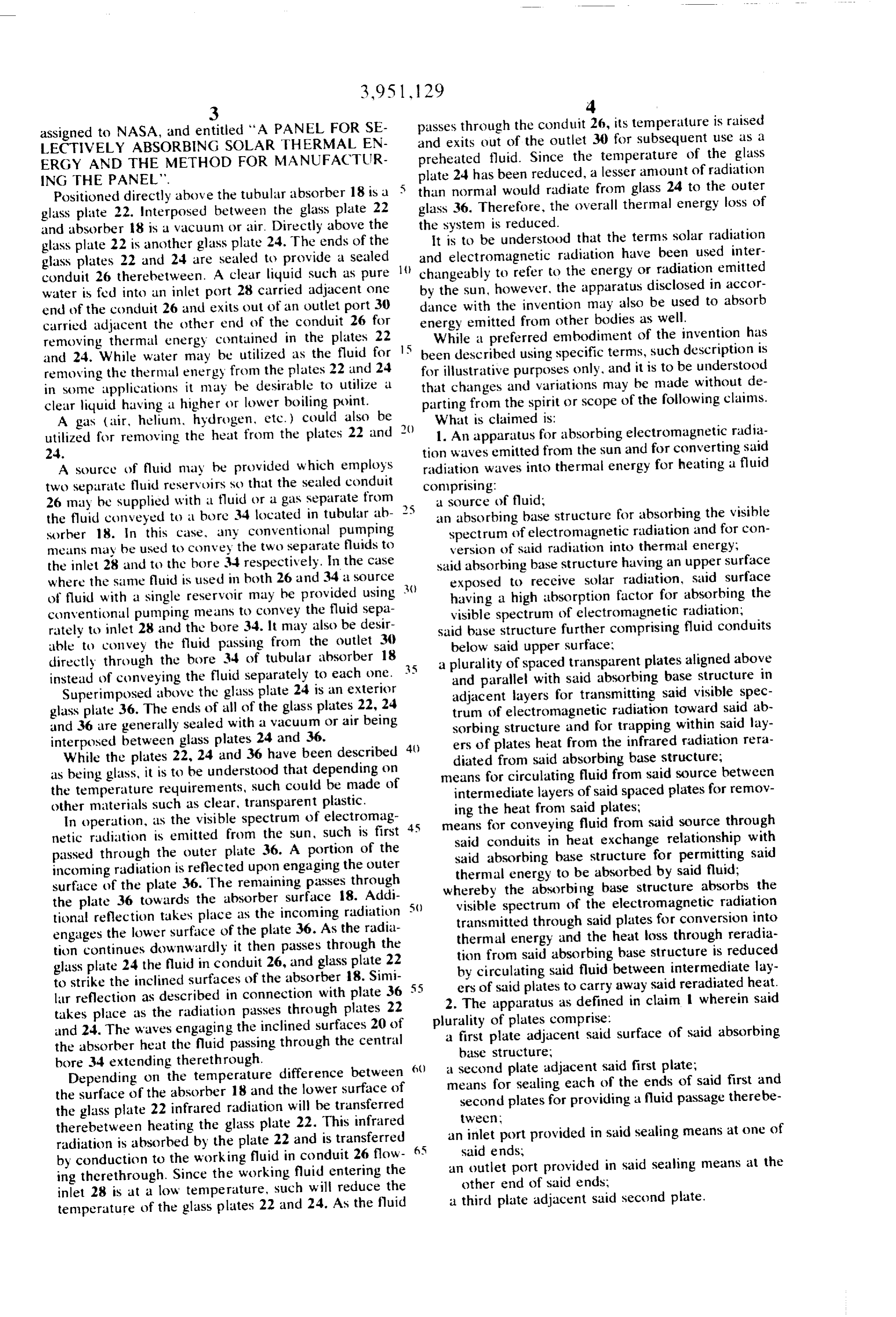
directly through the bore 34 of tubular absorber 18 a plurality of spaced transparent plates aligned above instead of conveying the fluid separately to each one. 5 and parallel with said absorbing base structure in Superimposed above the glass plate 24 is an exterior adjacent layers for transmitting said visible spec glass plate 36. The ends of all of the glass plates 22, 24 trum of electromagnetic radiation toward said ab and 36 are generally sealed with a vacuum or air being sorbing structure and for trapping within said lay interposed between glass plates 24 and 36. ers of plates heat from the infrared radiation rera While the plates 22, 24 and 36 have been described 40 diated from said absorbing base structure; as being glass, it is to be understood that depending on means for circulating fluid from said source between the temperature requirements, such could be made of intermediate layers of said spaced plates for remov other materials such as clear, transparent plastic. ing the heat from said plates; In operation, as the visible spectrum of electromag means for conveying fluid from said source through netic radiation is emitted from the sun, such is first 45 said conduits in heat exchange relationship with passed through the outer plate 36. A portion of the said absorbing base structure for permitting said incoming radiation is reflected upon engaging the outer thermal energy to be absorbed by said fluid; surface of the plate 36. The remaining passes through whereby the absorbing base structure absorbs the the plate 36 towards the absorber surface 18. Addi tional reflection takes place as the incoming radiation 50 visible spectrum of the electromagnetic radiation transmitted through said plates for conversion into engages the lower surface of the plate 36. As the radia thermal energy and the heat loss through reradia tion continues downwardly it then passes through the tion from said absorbing base structure is reduced glass plate 24 the fluid in conduit 26, and glass plate 22 by circulating said fluid between intermediate lay to strike the inclined surfaces of the absorber 18. Simi lar reflection as described in connection with plate 36 55 2.ers The of said plates to carry away said reradiated heat.
apparatus as defined in claim 1 wherein said takes place as the radiation passes through plates 22 plurality of plates comprise: and 24. The waves engaging the inclined surfaces 20 of a first plate adjacent said surface of said absorbing the absorber heat the fluid passing through the central base structure;
bore 34 extending therethrough.
Depending on the temperature difference between 60 ameans second plate adjacent said first plate; for sealing each of the ends of said first and the surface of the absorber 18 and the lower surface of second plates for providing a fluid passage therebe the glass plate 22 infrared radiation will be transferred tween therebetween heating the glass plate 22. This infrared an inlet port provided in said sealing means at one of radiation is absorbed by the plate 22 and is transferred by conduction to the working fluid in conduit 26 flow - 65 ansaid ends;
outlet port provided in said sealing means at the ing therethrough. Since the working fluid entering the other end of said ends;
inlet 28 is at a low temperature, such will reduce the a third plate adjacent said second plate. temperature of the glass plates 22 and 24. As the fluid
Page 6
3. The apparatus of claim 1 wherein said absorbing spectrum of the electromagnetic radiation and a base structure further comprises: low emittance factor;
a plurality of adjacent triangular member providing : said fluid conduits comprising a central bore extend plurality of angular absorbing surfaces, S ing through said triangular members for conveying a highly absorptive coating on said surfaces having a said fluid in heat exchange relationship. high absorption factor for absorbing the visible x: k xk xk sk
Provenance
- Collection
- Cited prior art
- Original PDF
- patentimages.storage.googleapis.com →
- Filed
- 1974-10-29
- Pages
- 6
- Method
- pdftotext (the PDF's own text layer) + pdftoppm 300dpi page scans
- Source
- Google Patents bibliographic record
- Granted
- 1976-04-20
- Inventors
- Lott W. Brantley, Jr.; National Aeronautics and Space Administration NASA
- Transcribed from
- patentimages.storage.googleapis.com →