patent · US5634339
Non-polluting, open brayton cycle automotive power unit
3 June 1997
Page 1 — bibliographic record
United States Patent 19 11 Patent Number: 5,634,339 Lewis et al. 45) Date of Patent: Jun. 3, 1997 54) NON-POLLUTING, OPEN BRAYTONCYCLE Kettler; "The Thermal Vehicle-A Pollution Free Concept," AUTOMOTIVE POWER UNIT Aug. 18-22, 1975 from the Record of the Tenth Intersociety Energy Conversion Engineering Conference.
75) Inventors: Ralph H. Lewis, 117 Mt. Etna Dr.,
Clayton, Calif. 94517; David G. DeVries, Karig & Drage; "Eutectic Molten Salt Thermal Wilson, Winchester, Mass. Storage System;” Oct. 1969 pp. 191-195 of J. Hydronautics,
73 Assignee: Ralph H. Lewis, Clayton, Calif. Wood, Applications of Thermodynamics, 2d., (c) 1982. Add ison-Wesley Publishing Co., Reading, Massachusetts, pp.
(21) Appl. No.: 497,622 62-64.
(51) Int. Cl. ...m. F02C 1/04 Primary Examiner-Ira S. Lazarus 52 U.S. Cl. .................................. 60/650; 60/659; 60/682 Assistant Examiner-Alfred Basichas 58 Field of Search ............................. 60/650, 659, 682: Attorney, Agent, or Firm-Donald E. Schreiber
The present invention includes a open-Brayton-cycle auto
3,894,605 7/1975 Salvadorini ........................... 180/65 R stored thermal energy. Thermal energy, absorbed from hot 4,089,176 5/1978 Ashe ............. ... 60/650 thermal-energy-storage material present in a working fluid 4,215,553 8/1980 Poirier et al. ............................. 60/650 heating vessel, heats a working fluid that passes through the 4,258,677 3/1981 Sanders ......... ... 123/142.5 unit's turbine. The unit also includes a rotary impeller that 4,259,836 4/1981 Finckh ...................................... 60/676 draws the flow of working-fluid into the unit from the 4262,484 4/1981 Jubb et al. ......... ... 60/659 surrounding atmosphere and discharges it into a working 4,463,799 8/1984 Takahashi et al. . ... 165/10 fluid heatregenerator. Within the regenerator, working fluid 4,768,345 9/1988 Kardas ...................................... 60/659 from the compressor is warmed by thermal energy from hot 5,207,268 5/1993 Krause et al. 165/104.11 working-fluid exhausted from the turbine. After passing 5,259,444 11/1993 Wilson ....................................... 165/8 5,385,214 1/1995 Spurgeon ................................ 180/304 through the regenerator, working-fluid from the turbine is 5,419,135 5/1995 Wiggs .................................... 60/641.8 discharged into the atmosphere. Working-fluid from the compressor flows from the regenerator through the heating
OTHER PUBLICATIONS vessel into the turbine. An alternator converts energy from Percival and Tsou; "Power from Thermal Energy Storage the turbine into electricity. The electric energy thus obtained Systems;" Oct. 29-Nov. 162 pp. 2-33+Figures 1-16; from powers a vehicle's electric drive motors. Sealed ceramic the Combined National Fuels and Lubricants, Powerplant tubes, filled with a material having a melting temperature and Transportation Meetings; Society of Automotive Engi within the operating temperature range of the thermal neers, Inc. energy-storage material, provide thermal energy storage. Garrett Fluid Systems Division, Allied-Signal Aerospace Regeneration of stored thermal energy may be achieved in Company, "Space Power for the New Frontier;" Date various ways including both a combustible-fuel burner and Unknown, pp. 19-23, 30-34, 36-37 and 41-42. an electrical heater, that are both located within the heating Meijer, "Prospects of the Stirling Engine for Vehicular vessel, and by an automated regeneration station. Propulsion;” copyright 1970; pp.169-185; from the Phillips
Technical Review, vol. 31, No. 5/6. 25 Claims, 3 Drawing Sheets
Page 2
Drawing sheet — no readable text.
Page 3
Drawing sheet — no readable text.
Page 4
Drawing sheet — no readable text.
Page 5
NON-POLLUTING, OPEN BRAYTON CYCLE ous closed-Brayton-cycle power systems which have used a AUTOMOTIVE POWER UNIT quantity of argon gas, continuously circulating in a closed
BACKGROUND OF THE INVENTION
loop, as a working fluid. Various heat sources including an electrical heat source, a diesel-fueled heat source, and a 1. Field of the Invention COso heat source have been used with these closed-Brayton The present invention relates generally to the technical cycle power systems.
field of motive power systems for automotive vehicles, and, A technical paper entitled "Power From Thermal Energy more particularly, to automotive-vehicle motive power sys Storage Systems” by Worth H. Percival and Michael Tsou tems that convert stored thermal energy into electricity for 10 presented at the Society of Automotive Engineers Combined energizing electric-vehicle driving motors. National Fuels and Lubricants, Powerplant and Transporta 2. Description of the Prior Art tion Meetings, Oct. 29 through Nov. 1, 1962, (the Percival Present and anticipated air-pollution regulations indicate paper"), using reports various proposals that have been made for stored thermal energy. For example the Percival paper that emission-free vehicles will be operating in major urban reports a proposal for electrically heating crushed stone areas in the foreseeable future. Presently, electricity appears 15 to be the only possible energy source to power an emission during off-load hours, and then subsequently using the Stored heat for space heating when electrical power system free vehicle. A significant difficulty with presently proposed load is high. The Percival paper also reports that heat stored electric vehicles is that they employ batteries which cur in refractory pebbles or spheres at temperatures as high as rently have an unsatisfactorily low energy density. The energy density of presently available batteries is so low that 20 3000 F has been used for brief intervals in heating air or a battery-powered vehicle intended to travel 400 miles other gases to a high temperature in high-speed wind tun between battery recharging can carry nothing other than the nels. In considering various alternatives for converting stored heat into mechanical energy, the Percival paper states batteries which power the vehicle's operation. that, in comparison with the Stirling engine's efficiency of Consequently, producing a useful battery-powered vehicle approximately 40%, it is questionable whether a Brayton with a 400-mile cruising range requires a major break 25 cycle gas turbine will ever reach an efficiency of 40%. The through in battery technology. Percival paper states unequivocally that the Brayton-cycle For scores of years in various industrial settings steam gas turbine "can not hope to compete on the basis of total powered locomotives have operated which lack any ability integrated work available from a thermal energy storage for heating water to make steam. Rather, such locomotives tank compared to the Rankine cycle steam cycle or Stirling are powered by stored thermal energy. The power source 30 engine.” The Percival paper also states carried by these locomotives is a heavily insulated water stored thermal energy into mechanical that in converting tank which is periodically filled with superheated water. This Brayton-cycle turbine achieves higher efficiencya than energy, closed
Superheated water provides the locomotive's power source. open-Brayton-cycle turbine.
The energy density of such superheated wateris so great that it has an energy density comparable to that of present 35 SUMMARY OF THE INVENTION electrical batteries. An object of the present invention is to provide a Employing hot water as a thermal-energy-storage pollution-free automotive vehicle capable of carrying a material, U.S. Pat. No. 5,385,214 which issued Jan. 31, 1995 practical load for a commercially practical distance. on an application filed by John E. Spurgeon (“the Spurgeon Another object of the present invention is to provide a patent”), discloses a motor vehicle having a “heat battery" 40 pollution-free automotive vehicle having performance com which supplies high-pressure steam to a conventional heat parable to present vehicles powered by internal-combustion engine that includes a steam turbine. The Spurgeon patent engines.
expressly discloses that the heat battery stores hot water at Another object of the present invention is to provide a a temperature of 374 degrees centigrade (“C.”), i.e. 705 pollution-free automotive vehicle having performance com degrees Fahrenheit (“F”), and at a pressure of 221 bar, i.e. 45 parable to present vehicles without requiring development of 3205 pounds per square inch ("PSI"). The Spurgeon patent a new energy technology.
employs hot water at this particular temperature and pres Another object of the present invention is to provide a sure because under those conditions the material's heat capacity appears to be infinite. pollution-free automotive vehicle which employs existing A technical paper entitled "The Thermal Vehicle-A 50 energy sources more efficiently.
Another object of the present invention is to provide a
Pollution Free Concept" by Jack R. Kettler presented at the pollution-free
"Tenth Intersociety Energy Conversion Engineering Con using existing automotive vehicle which can be assembled technologies.
ference held Aug. 18-22, 1975 ("the Kettler paper"), com Another object of the present invention is to provide a pares thermal and electric vehicles, emphasizing system pollution-free automotive vehicle which can be refueled design performance. The Kettler paper also compares alter quickly.
native types of heat engines and thermal-storage materials.
The Kettler paper reports that most automotive gas-turbine Yet another object of the present invention is to provide a engine studies have dealt with internal-combustion gas pollution-free automotive vehicle whose construction turbines. It comments that these studies are not pertinent to requires only plentiful and readily available materials. the thermal vehicle since they used a 1900° F turbine inlet 60 Yet another object of the present invention is to provide a temperature, which would be too high for a gas turbine if its lighter pollution-free automotive vehicle. working fluid were to be heated by an external source. The Yet another object of the present invention is to provide a Kettler paper further reports that a closed-cycle gas turbine pollution-free automotive vehicle powered by stored ther operating with external combustion had been designed with mal energy that does not require a condenser. a turbine inlet temperature of 1500°F. 65 Yet another object of the present invention is to provide a The Garrett Fluid Systems Division of Allied-Signal simpler pollution-free automotive vehicle powered by stored Aerospace Company has, over many years, developed vari thermal energy.
Page 6
Yet another object of the present invention is to provide a from the following detailed description of the preferred more cost-effective pollution-free automotive vehicle pow embodiment as illustrated in the various drawing figures. ered by stored thermal energy.
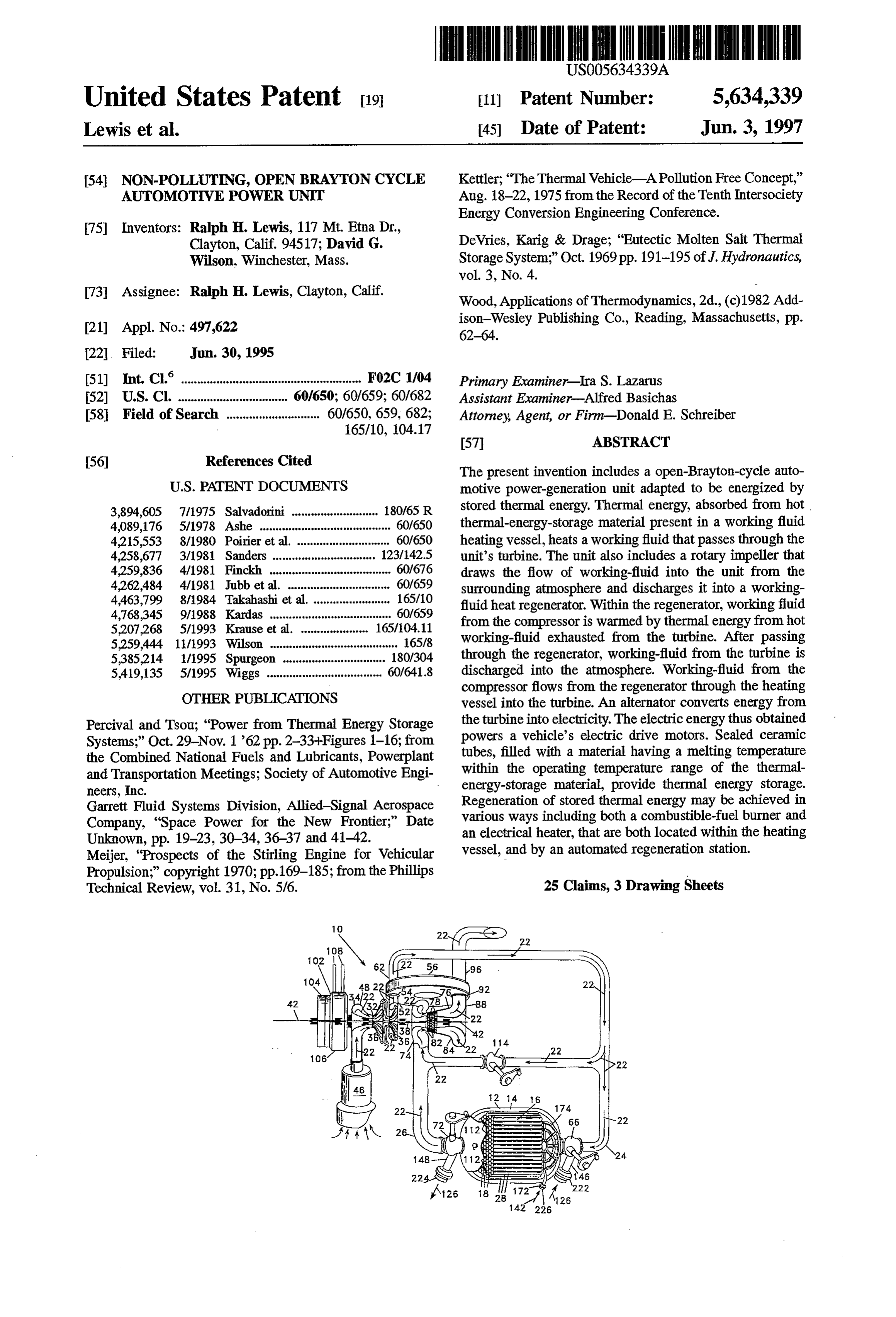
Briefly, the present invention includes a non-polluting, BRIEF DESCRIPTION OF THE DRAWINGS open-Brayton-cycle automotive power-generation unit. The FIG. 1 is a cross-sectional plan view of an open-Brayton automotive power-generation unit is specifically adapted to cycle automotive power-generation unit in accordance with be energized by thermal energy stored in a working-fluid the present invention together with its associated working heating vessel that contains a quantity of hot thermal fluid heating vessel that contains a quantity of thermal energy-storage material. To energize the automotive power energy-storage material;
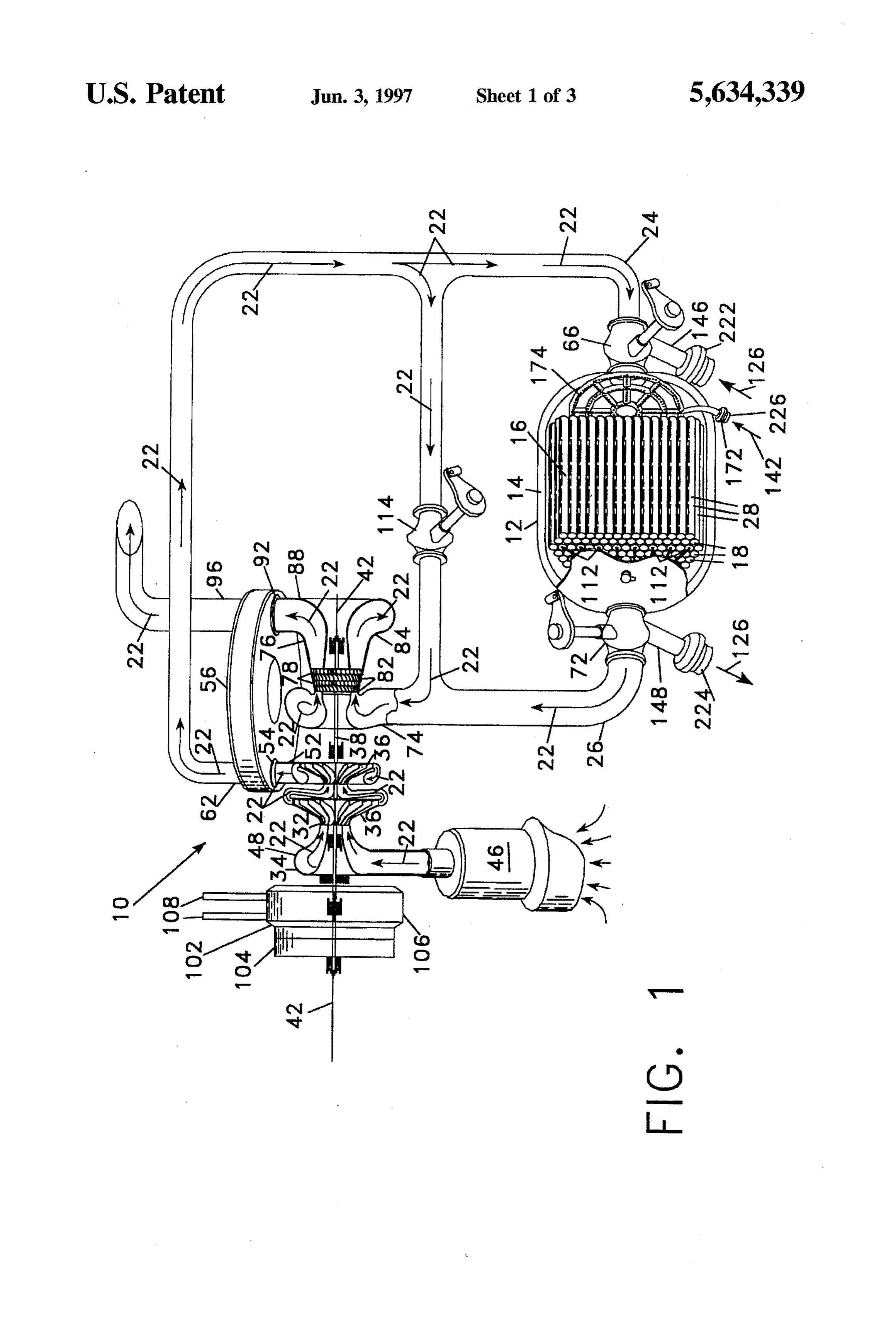
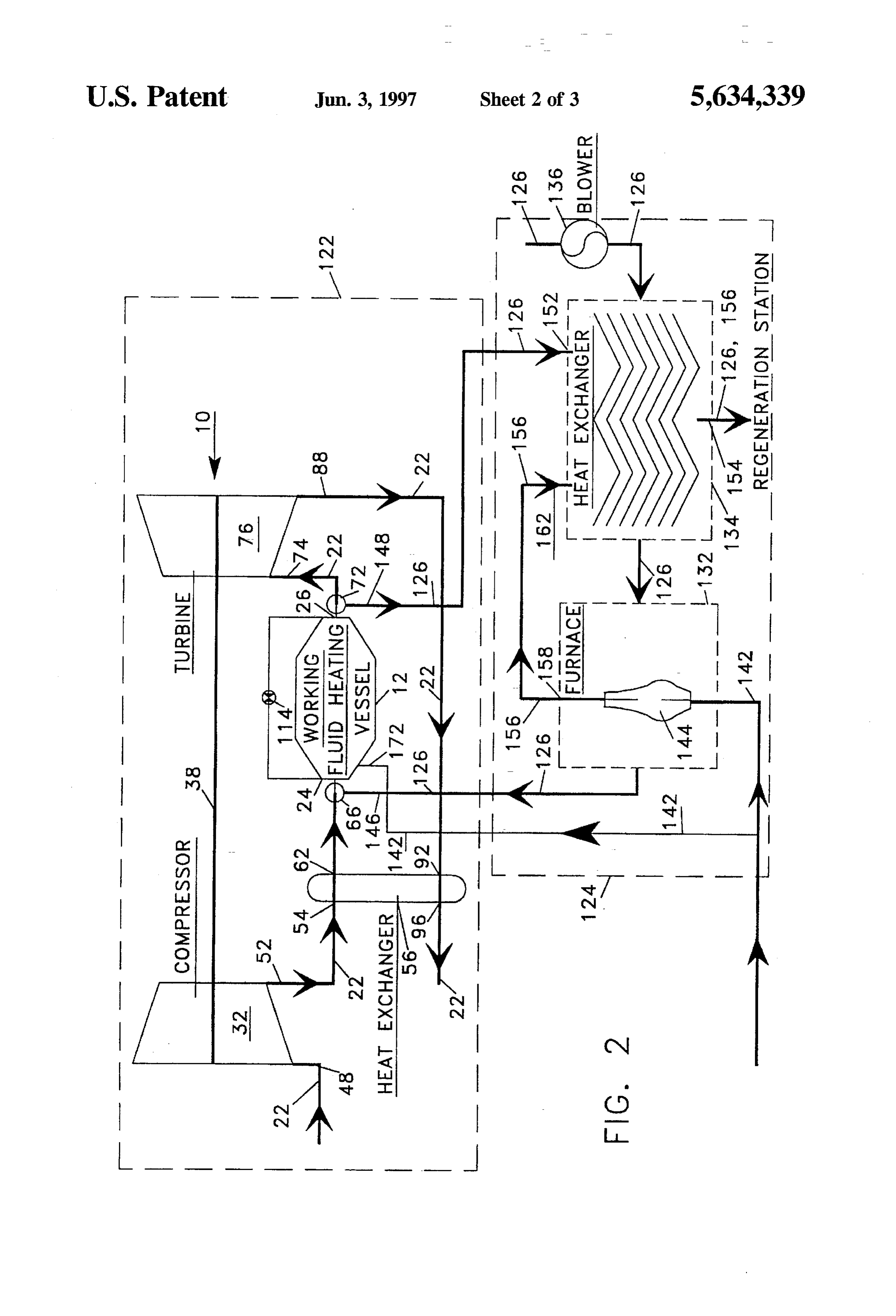
generation unit, a flow of comparatively cool gaseous 10 working-fluid enters the working-fluid heating vessel, is theFIG. 2 is a block diagram depicting fluid-flow circuits for automotive power-generation unit and the working-fluid heated by absorption of thermal energy from the hot heating vessel together with a preferred thermal thermal-energy-storage material, and then flows out of the regeneration station; and working-fluid heating vessel into an inlet of the power FIG. 3 is a cutaway perspective view of a portion of a generation unit's turbine. 15 motor vehicle positioned adjacent to the regeneration station
To supply the flow of cooler working-fluid to the working fluid heating vessel, the automotive power-generation unit of FIG. 2 which specifically illustrates a coupling for auto matically uniting the regeneration station with the motor includes a compressor. The power-generation unit's com vehicle during regeneration of the thermal-energy-storage pressor includes a impeller that is secured to a power 20 material.
generation-unit drive shaft which is also secured to a turbine wheel of the turbine. The power-generation unit supports the DETALED DESCRIPTION OF THE drive shaft so it is rotatable together with the impeller and PREFERRED EMBODIMENT turbine wheel about the drive shaft's longitudinal axis. The FIG. 1 is a cross-sectional plan view depicting a non flow of hot working-fluid past the turbine's wheel energizes 25 polluting, open-Brayton-cycle automotive power-generation the drive shaft's rotation. Rotation of the power-generation unit in accordance with the present invention, referred to by unit's compressor draws the flow of working-fluid from the the general reference character 10. As illustrated in FIG. 1, Surrounding atmosphere through a compressor inlet into the automotive power-generation unit. The power-generation the automotive power-generation unit ("APGU”) 10 is coupled to a working-fluid heating vessel (“WFHV") 12.
unit's compressor discharges the flow of working-fluid into The WFHV 12 includes an insulated outer housing 14 which a working-fluid heat regenerator. 30
Working-fluid from the power-generation unit's compres ("TESM”)a quantity encloses of hot thermal-energy-storage material sor flowing through the working-fluid heat regenerator is rial which may be selected16from 16. The TESM is preferably a ceramic mate among materials such as warmed by thermal energy transferred to such working-fluid silicon, boron carbide, alumina, aluminum carbide, or beryl from hot working-fluid discharged into the heatregenerator 35 lium oxide. A working fluid 22, as indicated from the power-generation unit's turbine. After the working arrows in FIG. 1, flows from a working-fluid by the various heating vessel fluid exhausted from the turbine passes through the heat inlet (“WFHVT) 24 of the WFHV 12, through the WFHV regenerator, it is discharged into the atmosphere surrounding 12, and out of a working-fluid heating vessel outlet the automotive power-generation unit. The working-fluid (“WFHVO”) 26. The working fluid 22 flowing through the from the power-generation unit's compressor, after being WFHV 12 is heated by absorbing thermal energy from the warmed within the heatregenerator, flows into the working hot TESM 16 present within the WFHV 12. fluid heating vessel. The ceramic TESM 16 is arranged to provide a porous The automotive power-generation unit preferably structure having a plurality of passages 18through which the includes an alternator coupled to the power-generation unit's working fluid 22 flows. A presently preferred form for the drive shaft which converts the drive shaft's rotational energy 45 into electric energy. The electric energy thus obtained pow TESM oxide 16, illustrated in FIG. 1, is that of sealed, beryllium tubes 28 which remain solidata temperature in excess ers a motor vehicle's electric drive motors.
of 2800 F Such ceramic tubes 28 are filled with silicon, or
The thermal-energy-storage material preferably includes some other suitable material, which melts at a temperature sealed tubes of a ceramic material that are filled with a between 2000 and 2800°F. As is readily apparent to those material which melts at a temperature that is within the 50 knowledgeable about energy release or absorption occurring operating temperature range of the thermal-energy-storage during a material's phase change between a solid and a material. Employing a material that undergoes a phase liquid, solidification of an appropriately selected material change from the liquid phase to the solid phase within the releases a significant amount of thermal energy. thermal-energy-storage material's operating temperature Accordingly, storing thermal energy in a appropriately range significantly increases the amount of thermal energy 55 selected TESM 16 which melts at a temperature which is in which the working-fluid heating vessel may store. the operating temperature range of the TESM 16 signifi The presentinvention also includes various different ways cantly increases the amount of energy which the WFHV 12 for regenerating the thermal energy stored in the thermal may store for release to the working fluid 22. energy-storage material including both a combustible-fuel To supply a flow of working fluid 22 to the WFHVI24 of burner located within the working-fluid heating vessel, and 60 the WFHV 12, the APGU 10 includes a two-stage centrifu an electrical heater energized by electricity produced by gal compressor 32. The compressor 32 includes an outer energy-recovering regenerative braking of the motor housing 34 that encloses two compressor disks 36 which are vehicle. Moreover, the present invention also includes an respectively secured to a drive shaft 38 having alongitudinal automated regeneration station adapted for quickly regen axis 42. Rotation of the compressor disks 36 together with erating cool thermal-energy-storage material. 65 the drive shaft38 about the longitudinal axis 42 draws aflow These and other features, objects and advantages will be of working fluid 22 from atmosphere surrounding the APGU understood or apparent to those of ordinary skill in the art 10, through a cyclonic air filter 46, and into the compressor
Page 7
32 through a compressor inlet 48. The working fluid 22 turbine wheels 78 rotate at 17,000 RPM. While the preferred being admitted into the compressor 32 through the air filter embodiment of the present invention envisions an axial-flow 46 generally carries particulates which the air filter 46 traps turbine 76, a APGU 10 in accordance with the present and retains to prevent damage to the APGU 10. The com invention may alternatively be constructed using a centrifu pressor 32 discharges the flow of working fluid 22 drawn gal flow turbine wheel, or any other suitable type of turbine from the atmosphere surrounding the APGU 10 from a wheel, instead of the preferred axial-flow turbine 76. compressor outlet 52. The heat regenerator 56 also includes a turbine exhaust For a APGU 10 intended to generate approximately 190 inlet horsepower ("HP") that is adapted for powering a motor turbine9276,thatandiswhich coupled to the turbine exhaust 88 of the receives the flow of working fluid 22 vehicle, the compressor 32 preferably includes two (2) 10 exhausted from the turbine 76. Within the heat regenerator centrifugal compressor disks 36 that are each respectively 56, the turbine exhaust inlet 92 is coupled to a heat approximately 8.0 inches in diameter and are preferably regenerator outlet 96. Accordingly, working fluid 22 injection molded from a carbon-fiber-reinforced material. exhausted from the turbine 76 enters the heatregenerator 56 The two-stage compressor 32 included in such a APGU 10 through the turbine exhaustinlet 92 and is discharged from preferably provides a compression ratio of two when the 15 the heat-regenerator outlet 96 of the heatregenerator 56 into compressor disks 36 rotate at 17,000 revolutions perminute the atmosphere surrounding the APGU 10. Within the heat (“RPM"). While the preferred embodiment of the present invention envisions a two-stage centrifugal compressor 32, regenerator 56 during operation of the APGU 10, thermal a APGU 10 in accordance with the present invention may turbine 76 tofrom energy flows hotter working fluid 22 received from the alternatively be constructed using from one to four or more compressor 32. This working cooler fluid 22 received from the centrifugal stages, or, for larger power outputs, an axial working fluid 22 received from thermal flow of the energy cools the turbine 76 while con centrifugal or an axial-flow compressor, or any other suit currently heating the working fluid 22 received from the able type of compressor, instead of the preferred centrifugal compressor 32.
compressor 32. Accordingly, a APGU 10 in accordance with the present invention may be assembled using any of the 25 in The heatregenerator 56 is preferably of a type disclosed U.S. Pat. No. 5,259,444 entitled "Heat Exchanger Con different types of impellers identified above for drawing the taining a Component Capable of Discontinuous Movement" flow of working fluid 22 into said compressor 32 through the compressor inlet 48 and discharging the flow of working that issued Nov. 9, 1993, on an application filed by David G. fluid 22 from the compressor outlet 52. Wilson (“the 444 Patent”). The 444 Patent is hereby The working fluid 22 discharged from the compressor 30 incorporated herein by reference.
outlet 52 of the compressor 32 enters a compressor inlet 54 possible to couple the the
While for powering motion of a motor vehicle it is drive shaft 38 mechanically to the of a heat regenerator 56 that is coupled to a working-fluid heat-regenerator outlet 62. Disposed between the working motor vehicle's wheels, for reasons described in greater fluid heat-regenerator outlet 62 of the heat regenerator 56 detail below the preferred embodiment of the APGU 10 and the WFHVI 24 of the WFHV 12, the APGU 10 of the 35 includes alternator 102 which preferably is of an axial gap present invention preferably includes a first thermal construction. The alternator 102 includes a rotor 104 that is regeneration control valve ("FTRCV") 66. Oriented in the coupled to the drive shaft 38 for rotation about the longitu position illustrated in FIG. 1, the FTRCV 66 permits work dinal axis 42. The alternator 102 also includes a stator 106 ing fluid 22 to flow unimpeded from the working-fluid that is fixed with respect to the APGU 10. Upon rotation of heat-regenerator outlet 62 into the WFHVI 24. the rotor 104 by the drive shaft 38, a pair of power output terminals
The WFHVO 26 of the WFHV 12 is coupled, through a electric current 108, included in the alternator 102, supply an second thermal-regeneration control valve ("STRCV") 72, APGU to an electrical load that is external to the
to an inlet 74 of a turbine 76. Oriented in the position load preferably includes a motor vehicle, such an external electrical illustrated in FIG. 1, the STRCV 72 permits hot working driving the motor vehicle'sone or more electric motors for wheels in a manner such as that fluid 22 to flow unimpeded from the WFHVO 26 into the 45 described in U.S. patent application Ser. No. 08/306.159 inlet 74. The turbine 76 includes a pair of axial-flow turbine entitled "Terrestrial Vehicle Motive Power Systems” that wheels 78 that are secured to the drive shaft 38 to be was filed Sep. 14, 1994, by Ralph H. Lewis rotatable about the longitudinal axis 42 thereof. Each of the application”). The 159 patent application is hereby (“the 159 patent turbine wheels 78 is respectively preceded by arow of stator porated herein by reference. incor blades 82 which project inward toward the drive shaft 38 50 from an outer housing 84 of the turbine 76. The turbine 76 During normal operation of the APGU 10, working fluid also includes a turbine exhaust 88 through which the flow of 22 flows out of the compressor 32 and into the heatregen working fluid 22 discharges from the turbine 76. The flow of erator 56 at a temperature of approximately 400° F and a hot working fluid 22 from the WFHV 12 which passes pressure of approximately 2 bars. Passage of the working through the turbine 76 induces rotation both of the turbine 55 fluid 22 through the heat regenerator 56 further heats the wheels 78 and of the drive shaft 38 to which they are working fluid 22 to a temperature of approximately 1535°F. secured. As described previously, such rotation of the drive The working fluid 22 is then further heated to a temperature shaft 38 also causes the compressor disks 36 to draw a flow of approximately 1850°F. upon passing through the WFHV of working fluid 22 from atmosphere surrounding the APGU 12 to enter the turbine 76 at that temperature and at a 10 into the compressor 32. pressure of approximately 1.8 bars. Upon being exhausted For a APGU 10 intended to generate approximately 190 from the turbine 76, the working fluid 22 is at a pressure of HP that is adapted for powering a motor vehicle, the turbine approximately
Passage of the 1.02 bars and at a temperature of 1570 F.
working fluid 22 through the heatregenerator 76 preferably includes two (2) axial-flow turbine wheels 78 56 further cools the working fluid 22 to a temperature of that are each respectively 7.00 to 8.00 inches in diameter and approximately 262°F.
are preferably fabricated from a suitable ceramic material. 65
The two-stage turbine 76 included in such a APGU 10 Operating in the preceding manner, the APGU 10 preferably provides an expansion ratio under two when the described herein together with the WFHV 12 weighs
Page 8
approximately 700 pounds and produces approximately 190 12 as adapted for inclusion in a motor vehicle. In addition, HP. Furthermore, operating in this manner the APGU 10 FIG. 2 illustrates a preferred thermal regeneration station converts thermal energy stored in the TESM 16 of the 124, enclosed within a dashed line, that is adapted for WFHV 12 into electrical energy available at the power quickly regenerating the thermal energy stored in the TESM output terminals 108 of the alternator 102 at an efficiency of 5 16 using a flow of a hot regenerating gas 126. The regen approximately 48 to 50%. When incorporated into a motor eration station 124 basically consists of a specially adapted vehicle that employs axial gap electric motors for driving the furnace 132 and heat regenerator 134. motor vehicle's wheels, thermal energy presentin the TESM The flow of regenerating gas 126 is initially drawn into 16 of the WFHV 12 is converted into driving energy for the vehicle with an overall efficiency of approximately 40 to 10 the regeneration station 124 from atmosphere surrounding 45%. Consequently, a WFHV 12 containing 600 pounds of the regeneration station 124 by a blower 136. The blower the TESM 16 stores sufficient thermal energy to power a 136 forces the regenerating gas 126 through the heat regen 4000 pound motor vehicle 300 miles without stopping to erator 134 in which the regenerating gas 126 is partially refuel at an average speed of 60 to 65 miles per hour. heated in a manner to be described hereinbelow. The regen As described above, the WFHV 12 includes a quantity of 15 erating gas 126 then flows through the furnace 132 wherein TESM 16 which, when the APGU 10 initially begins the regenerating gas 126 is further heated. To heat the operating, is preferably heated to a temperature of approxi regenerating gas 126 within the furnace 132, the furnace 132 mately 2,800°F. During operation of the APGU 10, the flow receives a flow of a combustible fuel 142, preferably natural of thermal energy from the TESM 16 within the WFHV 12 gas, which burns within a fire box. 144 located within the to the working fluid 22 flowing through the WFHV 12 cools furnace 132. Upon leaving the furnace 132 after flowing past the TESM 16 to a temperature of approximately 1,500°F. 20 the fire box 44, the regenerating gas 126 is preferably before the power produced by the APGU 10 becomes heated to a temperature of approximately 2800 F. insufficient for powering a motor vehicle. Consequently, the The hot regenerating gas 126 from the furnace 132 then TESM 16 included in the WFHV 12 must be periodically flows reheated just as a conventional internal-combustion engine which,into a regeneration gas inlet 146 of the FTRCV 66 during regeneration of the TESM 16, is oriented so motor vehicle must be periodically refueled. 25
The preferred embodiment of the present invention pro as to provide an unimpeded flow for the regenerating gas vides several alternative, and mutually compatible ways for 126 into the WFHV 12. After flowing through the WFHV reheating the TESM 16. For example, as disclosed in the 12, the regenerating gas 126 is directed by the STRCV 72 159 patent application, one way to partially reheat the through a regeneration gas outlet 148 back to a regeneration TESM 16 is to employ regenerative braking of a motor 30 gas inlet 152 of the heat regenerator 134. vehicle which incorporates the APGU 10. To permit reheat The still hot regenerating gas 126, in flowing from the ing the TESM 16 using electrical energy generated by regeneration gas inlet 152 through the heat regenerator 134 regenerative braking, the WFHV 12 includes electrical resis to a heat-regenerator exhaust 154, partially heats regenerat tive elements 112 by which electrical energy generated by ing gas 126 entering the heat regenerator 134 from the regenerative braking electrically heats the TESM 16. 35 blower 136. Within the heat regenerator 134, the regener Moreover, whenever a motor vehicle incorporating the ating gas 126 coming from the blower 136 is further heated APGU 10 operates so that regenerative braking supplies by a flow of hot combustion gas 156 flowing out of an electrical energy to the TESM 16, an automatically con exhaust 158 of the furnace 132 and into a combustion gas trolled bypass valve 114 opens to divert around the WFHV inlet 162 to the heat regenerator 134. Similar to the regen 12 the working fluid 22 flowing from the heatregenerator 56 40 erating gas 126flowing through the heatregenerator 134, the to the turbine 76. Because the bypass valve 114 provides an hot combustion gas 156 in flowing from the combustion gas alternative path by which the working fluid 22 may flow inlet 162 through the heat regenerator 134 to the heat from the working-fluid heat-regenerator outlet 62 of the heat regenerator exhaust 154 further heats regenerating gas 126 regenerator 56 to the inlet 74 of the turbine 76, during passing through the heat regenerator 134. normal operation of the APGU 10 in a motor vehicle, the 45 In addition to supplying hot regenerating gas 126 to the bypass valve 114 opens and closes in response to the power WFHV 12, the regeneration station 124 in accordance with load placed on the APGU 10 so the working fluid 22 flows the present invention also supplies a flow of combustible into the turbine 76 at a constant temperature. fuel 142 to the WFHV 12. As illustrated in FIG. 1, the In addition to using electrical energy generated by regen WFHV 12 also includes a combustible-fuel inlet port 172 erative braking for reheating the TESM 16 included in the 50 through which a flow of combustible fuel 142, preferably WFHV 12, as described in the 159 patent application if the natural gas, is introduced into the WFHV 12. Moreover, motor vehicle employing the APGU 10 is stationary, the disposed within the WFHV 12 are burners 174 in which the TESM 16 may be reheated by supplying to the electrical combustible fuel 142 mixes with the regenerating gas 126 to resistive elements 112 electrical energy provided by a source burn in intimate contact with the TESM 16 so the thermal of electrical energy that is external to the motor vehicle, e.g. 55 energy of such burning couples directly to the TESM 16. an electric power utility. Operating in the preceding manner, the hot gas method for While reheating of the TESM 16 using electrical energy regenerating the thermal energy stored in the TESM 16 is easy, safe, and convenient, in general it is not the least operates at an overall efficiency of approximately 98%. This expensive way of recharging the energy stored within the efficiency for regeneration of the thermal energy stored in WFHV 12. Generally, it is cheaper and more energy efficient 60 the TESM 16 combined with the efficiency for conversion of to regenerate the TESM 16 by passing through the WFHV thermal energy stored in the TESM 16 into electrical energy 12 a flow of a gas heated directly by burning a combustible by the APGU 10 results in an overall efficiency of approxi fuel. Moreover, depending upon the type of fuel burned and mately 45 to 50%. Correspondingly, a motor vehicle incor the manner in which it is burned, it is possible to regenerate porating the APGU 10 disclosed herein operates an overall the TESM 16 without air pollution. 65 efficiency of 35 to 40% in converting energy in the com The block diagram of FIG. 2 illustrates within a dashed bustible fuel 142 into driving energy for the vehicle's line 122 fluid-flow circuits for the APGU 10 and the WFHV wheels. This energy efficiency for a motor vehicle powered
Page 9
by the APGU 10 compares most favorably with the energy The overall efficiency of the APGU 10 for converting efficiency of a conventional motor vehicles powered by a thermal energy into electrical energy may be further standard internal-combustion engines which presently dem increased beyond that described above. An approach for onstrate a comparable energy efficiency of approximately improving the efficiency of the APGU 10 is to increase the 14-28%. number of compressor disks 36 from two (2) to four (4), FIG. 3 is a cutaway perspective view of a portion of a correspondingly increasing the number of turbine wheels 78 motor vehicle, referred to by the general reference character from two (2) to four (4), and passing the working fluid 22 182, positioned adjacent to the regeneration station 124. discharged from the first pair of compressor disks 36through FIG. 3 specifically illustrates an automated coupling 184 an intercooler before admitting the working fluid 22 into the which unites the regeneration station 124 with the motor O second pair of compressor disks 36. Employing the preced vehicle 182 during regeneration of the TESM 16. The ing approach for enhancing the efficiency of the APGU 10 illustration of FIG. 3 depicts wheels 186, drive shafts 188, makes it feasible to attain an overall efficiency of 60% for disc brakes 192, electric driving motor 194, a portion of a the conversion of thermal energy stored in the TESM 16 into chassis 196 of the motor vehicle 182, and a partially electrical energy discharged from the power output termi cut-away view of the WFHV 12. 15 nais 108.
Before commencing regeneration of the TESM 16, the While the preferred embodiment of the WFHV 12 has automated coupling 184 is located beneath ground level and been described hereinabove, it is intended that the present blocked by a cover plate 198. One of the wheels 186 of the invention encompasses the APGU 10 if adapted for use in motor vehicle 182 is then positioned in a depressed trough conjunction with working-fluid heating vessels having alter 202 of a fixed vehicle positioning plate 204. Disposing the native structures and/or employing other thermal-energy wheel 186 in the trough 202 fixes the location of the motor storage materials. For example, the APGU 10 of the present vehicle 182 with respect to the automated coupling 184. invention may be adapted for use with a working-fluid After the wheel 186 has been positioned in the trough 202, heating vessel that contains a thermal-energy-storage mate the cover plate 198 automatically opens and the automated rial such as lithium hydride or lithium fluoride, or other coupling 184 rises out of the ground toward the WFHV 12 25 materials such as those listed in col. 5 at lines 43-54 of U.S. that is located directly above. The automated coupling 184 Pat. No. 4,207,268 which is hereby expressly incorporated includes a hot gas source line 212, a hot gas return line 214, herein by reference. Similarly, in principle a heat battery and a combustible-fuelline 216. The hot gas source line 212 similar to the type disclosed in U.S. Pat. No. 4,258,667, and the hot gas return line 214 provide conduits by which the which is also hereby expressly incorporated herein by regenerating gas 126 flows through the WFHV 12 immedi 30 reference, could be used with the APGU 10. ately after the automated coupling 184 extends sufficiently While gaseous regeneration of the TESM 16 has been far above ground level to mate the lines 212, 214 and 216 described herein as using a combustible-fuel to heat air that with corresponding ports 222, 224 and 226 of the WFHV 12 is forced through the WFHV 12, the present invention illustrated in FIG. 4. After the regenerating gas 126 begins envisions using a gas of any composition that is heated in flowing through the WFHV 12, the regeneration station 124 35 any way to a temperature that is sufficiently hot for restoring then supplies the combustible fuel 142 to the WFHV 12 thermal energy to the TESM 16.
through the combustible-fuel line 216. After the TESM 16 Although the present invention has been described in has been regenerated, the flows of the regenerating gas 126 terms of the presently preferred embodiment, it is to be and the combustible fuel 142 are terminated, the automated understood that such disclosure is purely illustrative and is coupling 184 retracts away from the motor vehicle 182 to not to be interpreted as limiting. Consequently, without return to a subterranean position, and the cover plate 198 departing from the spirit and scope of the invention, various returns to a position blocking the automated coupling 184. alterations, modifications, and/or alternative applications of By sensing and monitoring the temperature of the regen the invention will, no doubt, be suggested to those skilled in erating gas 126 returning to the regeneration station 124 the art after having read the preceding disclosure. from the WFHV 12, the regeneration station 124 may both 45 Accordingly, it is intended that the following claims be monitor the regeneration state of the TESM 16, and measure interpreted as encompassing all alterations, modifications, or the quantity of energy required to regenerate the TESM 16. alternative applications as fall within the true spirit and By monitoring the quantity of energy required to regenerate scope of the invention.
the TESM 16, the regeneration station 124 can determine an What is claimed is:
appropriate price for the quantity of energy deposited into 50 1. A non-polluting, open-Brayton-cycle automotive the TESM 16. power-generation unit comprising: While the regeneration station 124 is preferred for effi a working-fluid heating vessel having a heating-vessel ciently and Swiftly regenerating the thermal energy stored in working-fluid inlet for receiving a flow of cooler gas the TESM 16 of the WFHV 12, slower thermal energy eous working fluid, and having a heating-vessel regeneration using hot gas may be obtained using a simpler 55 working-fluid outlet from which hotter gaseous work system. In such a simpler system, the blower 136 supplies ing fluid flows, the flow of working fluid through the cool regenerating gas 126 directly to the regeneration gas working-fluid heating vessel from the heating-vessel inlet 146 of the FTRCV 66, and the combustible fuel 142 is working-fluid inlet to the heating-vessel working-fluid supplied only to the combustible-fuel inlet port 172 of the outlet being heated by absorption of thermal energy WFHV 12. While such a simplified system, suitable for from ceramic thermal-energy-storage material within installation in a garage of a house, does not achieve the same the working-fluid heating vessel, at least some of the energy efficiency as the regeneration station 124, it still ceramic thermal-energy-storage material within the achieves an overall efficiency of approximately 40 to 45%. working-fluid-heating vessel being formed into a plu This efficiency for regeneration of the thermal energy stored rality of sealed ceramic tubes that are respectively filled in the TESM 16 yields an overall motor vehicle efficiency of 65 with a phase-change material which melts at a tem 35 to 40% in converting energy in the combustible fuel 142 perature within an operating temperature range of the into driving energy for the vehicle's wheels. thermal-energy-storage material;
Page 10
a power-generation-unit drive shaft secured within said the working-fluid-heating vessel is beryllium oxide, and the automotive power-generation unit to be rotatable about phase-change material within the sealed ceramic tubes is a longitudinal axis of said power-generation-unit drive silicon.
shaft; 3. The automotive power-generation unit of claim 1 a power-generation-unit compressor having a impeller wherein during normal operation of the automotive power that is secured to said power-generation-unit drive shaft generation unit said power-generation-unit compressor has a so as to be rotatable together with said power pressure ratio less than three.
generation-unit drive shaft about the longitudinal axis 4. The automotive power-generation unit of claim 1 of said power-generation-unit drive shaft, said power further comprising an alternator having a fixed stator and a generation-unit compressor having a compressor inlet 10 moveable rotor which is coupled to the power-generation for admitting a flow of working fluid into said auto unit drive shaft of said automotive power-generation unit so motive power-generation unit from atmosphere sur as to be rotatable by said power-generation-unit drive shaft, rounding said automotive power-generation unit, said said alternator also having a pair of alternator power-output power-generation-unit compressor also having a terminals for supplying an electric current to an external working-fluid compressor outlet for discharging the 15 electrical load,drive rotation of said rotor by said power flow of working fluid from the power-generation-unit generation-unit ate an electrical shaft causing said alternator to gener potential across the pair of alternator power compressor, rotation of the power-generation-unit drive output terminals.
shaft together with the impeller secured thereto draw 5. The automotive power-generation unit of claim 4 ing the flow of working fluid into said power wherein generation-unit compressor through the compressor 20 generationduring normal operation of the automotive power unit said power-generation-unit compressor has a inlet and discharging the flow of working fluid from the pressure ratio less than three.
working-fluid compressor outlet; 6. The automotive power-generation unit of claim 4 a power-generation-unit turbine having a turbine wheel wherein the alternator is an axial-gap alternator. that is secured to said power-generation-unit drive shaft 7. The automotive power-generation unit of claim 6 so as to be rotatable together with said power 25 wherein during normal operation of the automotive power generation-unit drive shaft about the longitudinal axis generation unit said power-generation-unit compressor has a of said power-generation-unit drive shaft, said power pressure ratio less than three.
generation-unit turbine having a turbine inlet that is 8. The automotive power-generation unit of claim 1 coupled to the heating-vessel working-fluid outlet of wherein the working-fluid heating vessel further comprises the working-fluid heating vessel and through which 30 a thermal-energy-regeneration means adapted for increasing said power-generation-unit turbine receives a flow of the thermal energy stored in the thermal-energy-storage hot gaseous working fluid from the heating-vessel material.
working-fluid outlet after such working fluid has been 9. The automotive power-generation unit of claim 8 heated while passing through said working-fluid heat wherein the thermal-energy-regeneration means includes: ing vessel, and said power-generation-unit turbine also 35 an air inlet through which a atmosphere surrounding said having a turbine exhaust through which the flow of automotive power-generation unit may be introduced working fluid discharges from said power-generation into and circulated throughout the thermal-energy unit turbine, the flow of working fluid passing through storage material contained within said working-fluid said power-generation-unit turbine inducing rotation heating vessel;
both of said turbine wheel and of said power a combustible-fuel inlet port adapted to receive and generation-unit drive shaft of said automotive power introduce into the working-fluid heating vessel a com generation unit; and bustible fuel; and a working-fluid heatregenerator having a turbine-exhaust a burner adapted to receive combustible fuel introduced inlet that is coupled to the turbine exhaust of said into the working-fluid heating vessel, and to burns the power-generation-unit turbine for receiving the flow of 45 combustible fuel within the working-fluid heating ves the working fluid exhausted from said power sel thereby generating heat within the working-fluid generation-unit turbine which said working-fluid heat heating vessel.
regenerator discharges into the atmosphere surrounding 10. The automotive power-generation unit of claim 8 said automotive power-generation unit from a heat wherein the thermal-energy-regeneration means further regenerator outlet, said working-fluid heat regenerator 50 includes an electric heater.
also including a heat-regenerator compressor working 11. The automotive power-generation unit of claim 10 fluid inlet that is coupled to the working-fluid com wherein during normal operation of the automotive power pressor outlet of said power-generation-unit compres generation unit said power-generation-unit compressor has a sor for receiving the flow of working fluid from said pressure ratio less than three.
power-generation-unit compressor which said 55 12. The automotive power-generation unit of claim 8 working-fluid heatregenerator discharges from a heat wherein the thermal-energy-regeneration means further regenerator working-fluid heating-vessel outlet into the includes a hot fluid exchange port into said working-fluid heating-vessel working-fluid inlet of the working-fluid heating vessel through which a hot-fluid may be introduced heating vessel, a flow of thermal energy within said into and circulated throughout the thermal-energy-storage working-fluid heat regenerator cooling the flow of material contained within said working-fluid heating vessel. working fluid passing through the working-fluid heat 13. The automotive power-generation unit of claim 12 regenerator from the power-generation-unit turbine wherein during normal operation of the automotive power while concurrently heating the flow of working fluid generation unit said power-generation-unit compressor has a passing through the working-fluid heat regenerator pressure ratio less than three.
from the power-generation-unit compressor. 65 14. The automotive power-generation unit of claim 12 2. The automotive power-generation unit of claim 1 wherein said thermal-energy-regeneration means of the wherein the ceramic thermal-energy-storage material within working-fluid heating vessel further includes:
Page 11
a combustible-fuel inlet port adapted to receive and 22. The automotive power-generation unit of claim 19 introduce into the working-fluid heating vessel a com wherein the thermal-energy-regeneration means includes: bustible fuel; and an air inlet through which a atmosphere surrounding said a burner adapted to receive combustible fuel introduced 5 automotive power-generation unit may be introduced into the working-fluid heating vessel, and to burns the into and circulated throughout the thermal-energy combustible fuel within the working-fluid heating ves storage material contained within said working-fluid sel thereby generating heat within the working-fluid heating vessel;
heating vessel. a combustible-fuel inlet port adapted to receive and 15. The automotive power-generation unit of claim 12 introduce into the working-fluid heating vessel a com wherein the thermal-energy-regeneration means further O bustible fuel; and includes an electric heater.
16. The automotive power-generation unit of claim 15 a burner adapted to receive combustible fuel introduced wherein during normal operation of the automotive power into the working-fluid heating vessel, and to burns the generation unit said power-generation-unit compressor has a combustible fuel within the working-fluid heating ves pressure ratio less than three. 15 sel thereby generating heat within the working-fluid 17. The automotive power-generation unit of claim 8 heating vessel.
wherein the working-fluid heating vessel further comprises 23. The automotive power-generation unit of claim 19 a bypass valve coupled between the heat-regenerator wherein the thermal-energy-regeneration means further working-fluid heating-vessel outlet of said working-fluid includes a hot fluid exchange port into said working-fluid heat regenerator and the turbine inlet of said power 20 heating vessel through which a hot-fluid may be introduced generation-unit turbine that is adapted for diverting around into and circulated throughout the thermal-energy-storage the working-fluid heating vessel the working fluid which material contained within said working-fluid heating vessel. flows from said working-fluid heat regenerator to said 24. The automotive power-generation unit of claim 23 power-generation-unit turbine.
18. The automotive power-generation unit of claim 17 generationduring 25 wherein unit normal operation of the automotive power said power-generation-unit compressor has a wherein during normal operation of the automotive power pressure ratio less than three. generation unit said power-generation-unit compressor has a 25. The automotive power-generation unit of claim 23 pressure ratio less than three.
19. The automotive power-generation unit of claim 17 wherein said thermal-energy-regeneration means of the wherein the ceramic thermal-energy-storage material within 30 working-fluid heating vessel further includes: the working-fluid-heating vessel is beryllium oxide, and the a combustible-fuel inlet port adapted to receive and phase-change material within the sealed ceramic tubes is introduce into the working-fluid heating vessel a com silicon. bustible fuel; and 20. The automotive power-generation unit of claim 19 a burner adapted to receive combustible fuel introduced wherein the thermal-energy-regeneration means further 35 into the working-fluid heating vessel, and to burns the includes an electric heater. combustible fuel within the working-fluid heating ves 21. The automotive power-generation unit of claim 19 sel thereby generating heat within the working-fluid wherein during normal operation of the automotive power heating vessel.
generation unit said power-generation-unit compressor has a pressure ratio less than three.
Provenance
- Collection
- Cited prior art
- Original PDF
- patentimages.storage.googleapis.com →
- Filed
- 1995-06-30
- Pages
- 11
- Method
- pdftotext (the PDF's own text layer) + pdftoppm 300dpi page scans
- Source
- Google Patents bibliographic record
- Granted
- 1997-06-03
- Inventors
- Ralph H. Lewis; David G. Wilson
- Transcribed from
- patentimages.storage.googleapis.com →