patent · US3118437
Means for concentrating solar energy
21 January 1964
Page 1
Drawing sheet — no readable text.
Page 2
Jan. 21, 1964 L. E. HUNT 3,118,437
MEANS FOR CONCENTRATING SOLAR ENERGY
Filed Aug. 8, 196l 3. Sheets-Sheet 2
ARAY of AMfeeloes AAV/MG
A OA tave Atom All 72
THAr of Mireoe
Page 3
Drawing sheet — no readable text.
Page 4
United States Patent Office 3,118,437 Patented Jan. 21, 1964
the rays striking the first reflective surface to converge 3,118,437 onto substantially one point or limited area.
MEANS FOR CONCENTRATING SOLAR ENERGY The effective curvature of both the collector mirror and Lleweiya E. Hunt, 67 Victoria Ave., Vereeniging, that of the duplex mirror, each preferably is or corre Transvaal, Republic of South Africa sponds to a parabola.
Filed Aug. 8, 1961, Ser. No. 130,117 In a particular embodiment of the invention the curved Claims priority, application South Africa Sept. 15, 1960 reflective surface comprises a number of relatively nar 5 Clains. (C. 126-270) row, flat reflective members placed side by side so as to approach in effect a parabola and to approximate the ef
The present invention relates to an improved means O for concentrating solar energy, more particularly for the fectInofa apreferred continuously curved surface.
embodiment of the invention the rela utilisation of said solar energy for the purpose of heating.
A great number of appliances utilising solar energy that the curvature of reflective tively narrow, flat, members are so mounted rely on the concentration of solar energy by suitable ever shape and whenever desired may the parabola be altered to what or required.
means, e.g. by means of a reflective surface or surfaces. 5 The “duplex' mirror or reflective surface, preferably A concave reflective surface curved in three dimensions having a parabolic curvature or the approximate effect of or assimilating a three-dimensional curvature has hither parabolic curvature, may be similar to a “drive-in' cinema to been found to be the most suitable and effective, as rays screen. The “duplex' mirror or reflective surface is pref from all parts of the reflective surface are concentrated erably somewhat smaller than the collector mirror or re substantially on one point. Being curved in three dimen sions, however, raises the cost considerably and in fact flective surface and is positioned a suitable distance from the collector mirror or reflective surface and some dis makes it prohibitive in some cases. tance of the ground.
It is the object of the present invention to provide a The collector mirror or reflective surface or set of re means for concentrating solar energy easily, economically flective surfaces may be mounted upon a track or the and efficiently. like, said track preferably being circular so that the col It is a further object of the invention to provide a sys lector mirror or set of reflective surfaces may be rotated tem by means of which solar energy may be projected in accordance with the position of the sun in such a man downwards onto a point so that in the case of a melting ner that it always faces the sun.
pot or the like, the Solar energy may pass into said pot or The “duplex' mirror or reflective surface is preferably the like through the opening at the top instead of through 30 also mounted on a track or the like, so that it may be ad the sides. justed to any desired position, so that rays from the col Further objects, advantages and applications of the in lector mirror or reflective surface are always reflected onto vention will become apparent from the following descrip said "duplex' mirror or reflective surface. tion.
A means for concentrating solar energy in accordance In a preferred embodiment of the invention, both the collector mirror or reflective surface or set of reflective with the invention comprises a system of two reflective surfaces, and the "duplex' mirror or reflective surface may surfaces or two sets of reflective surfaces facing each be tilted in any direction so that a maximum concentra other, each of which has or produces the effect of a two tion of rays fall onto said mirrors or reflective surfaces. dimensional concave curvature, said reflective surfaces be The mirrors or reflective surfaces may be constructed ing arranged so that the one reflective surface or set of 40 of any suitable material, e.g. metal or alloy, having a re reflective surfaces faces the sun, herein referred to as flective surface. The reflective surfaces are preferably collector mirror, and so that the parallel rays of the sun hardened so as to prevent damage or dulling by the ele falling thereon are reflected onto the second reflective ments of the weather, surface, which has its back to the sun and is herein re In a particular embodiment of the invention, if the ferred to as a duplex mirror, in such a manner that in energy is to be used to melt metals or the like in a melt planes parallel to the effective axes of curvature of the ing pot or the like, the mirrors or reflective surfaces are first reflective surface or set of surfaces, the rays continue so arranged that the rays are reflected downwards onto to proceed parallel to one another towards the second re the melting pot or the like, so that said rays pass through flective surface, whereas in planes normal or at an angle the open end into said pot or the like instead of through thereto, the rays are converging, said second reflective the walls.
surface reflecting the rays in such a manner that after In one embodiment of the invention, the melting pot reflection from the second surface or set of surfaces the may be tilted so that the open end can always be turned rays will also converge in those planes in which they were towards the reflected sun rays. formerly parallel, while the degree of convergence pro The melting pot or boiler or the like is preferably sta duced by the first reflective surface or set of surfaces re 5 5 tionary whilst the reflective surfaces may be moved to mains substantiaily unchanged, the effective axes of curva follow the sun.
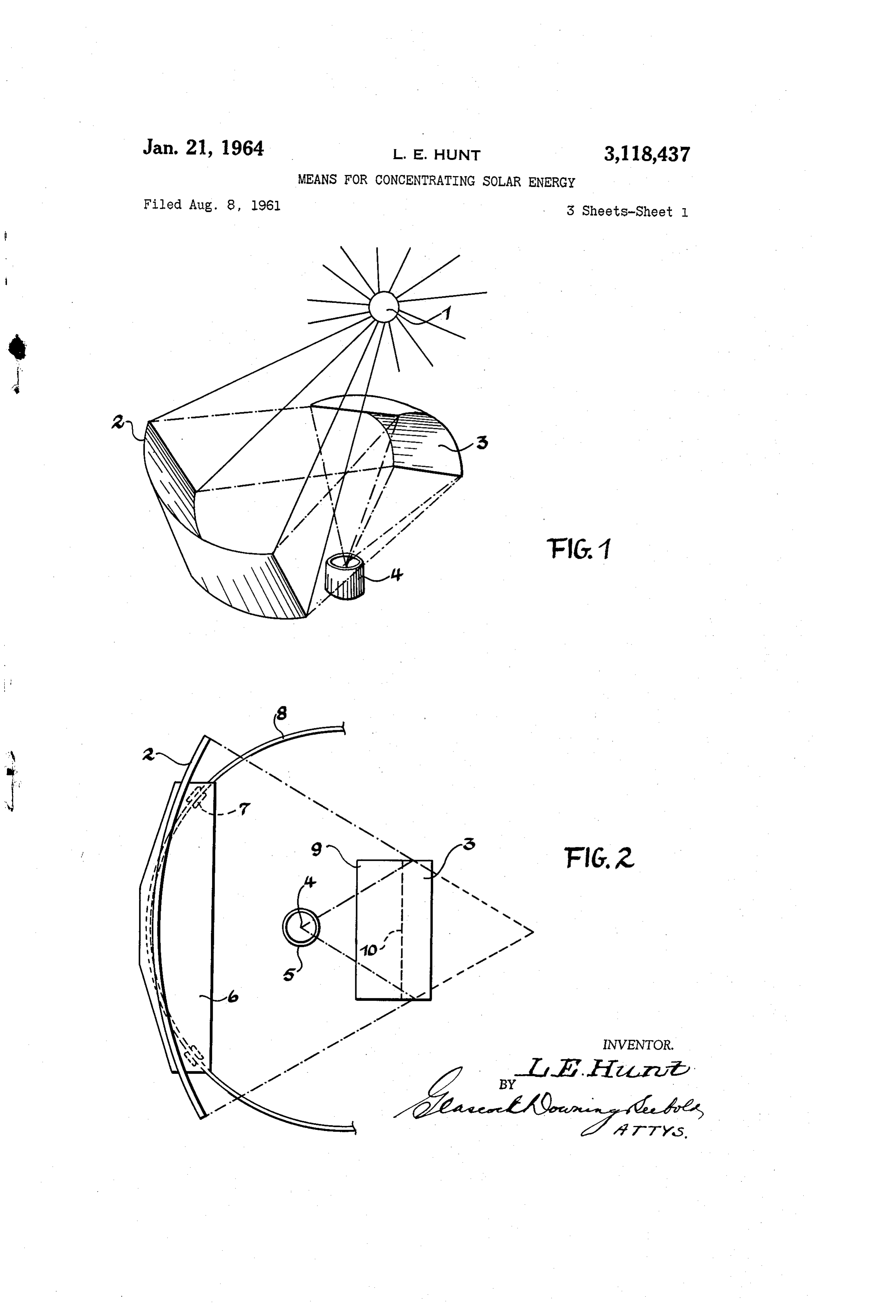
ture of the second surface or set of surfaces being normal The invention and the manner in which it may be put to the effective axes of curvature of the first surface or set into practice will be further described by way of the fol of surfaces and in which the focal length of the two-di lowing examples with reference to the drawings without mensionally curved collector mirror or reflective surface 60 thereby limiting the scope of the invention. is greater than that of the corresponding “duplex” mirror FIGURE 1 is a schematic perspective representation or reflective surface, the reflective surfaces or mirrors of a solar energy concentrating device in accordance with further being arranged in such a way that the sum of the the invention.
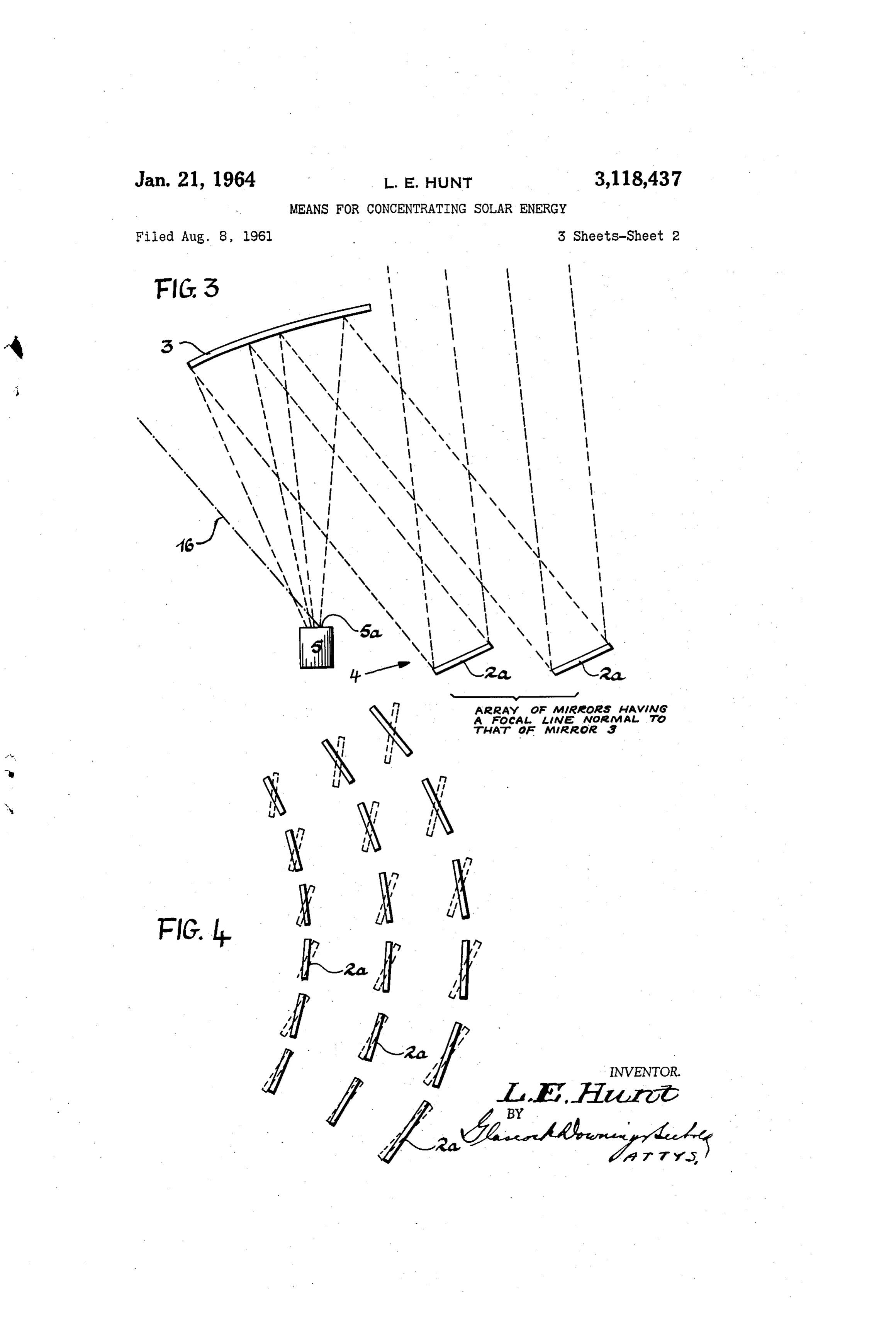
distances between the collector mirror or reflective sur FIGURE 2 shows a plan view of a solar energy con face and the “duplex' mirror or reflective surface and centrating device in accordance with the invention. betwen the “duplex' mirror or reflective surface and the FIGURE 3 is a diagrammatic vertical section through point of application corresponds to or approximates the a solar energy concentrating installation in accordance focal length of the collector mirror or reflective surface with the invention.
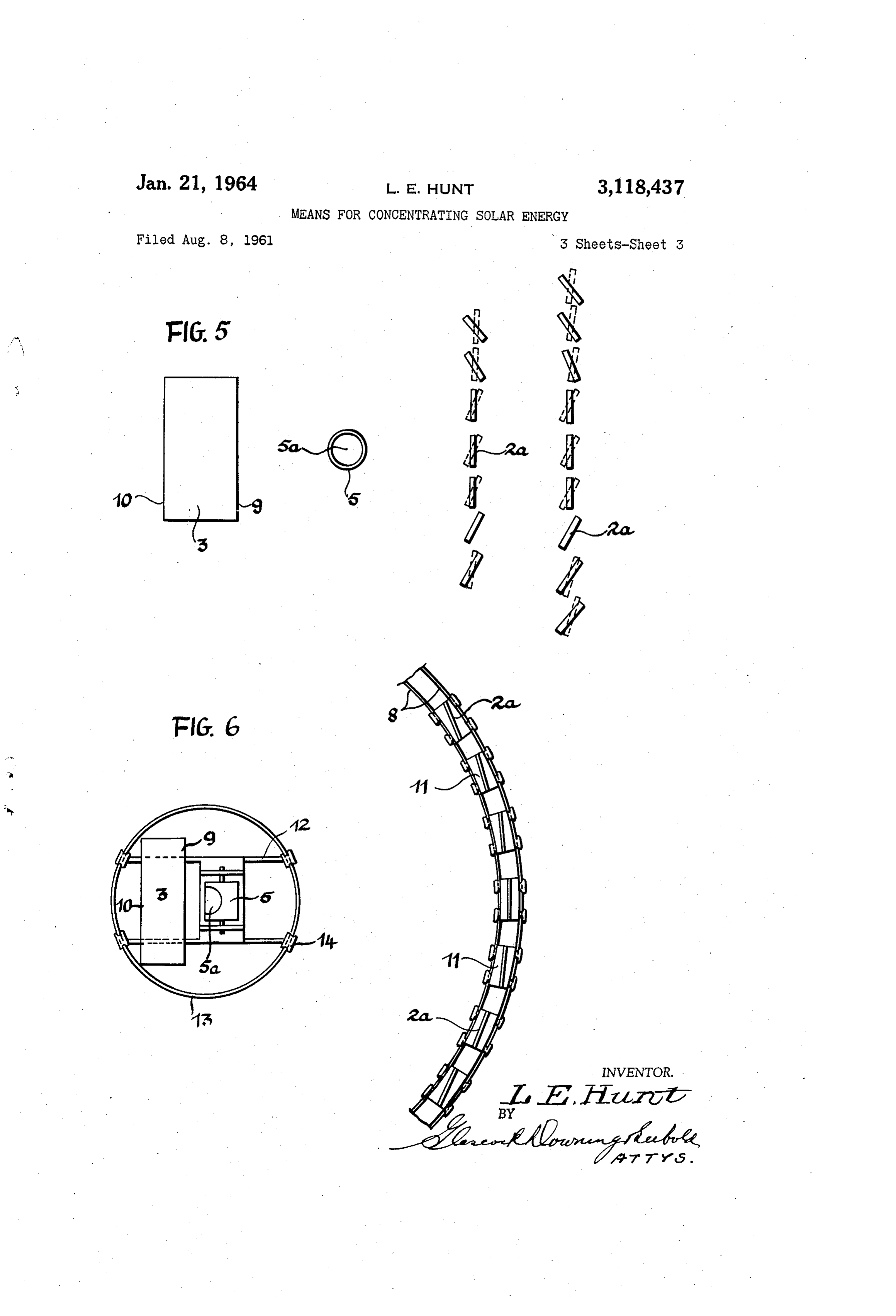
whilst the distance between the “duplex” mirror or re FIGURE 4 shows a side view of an arrangement of flective surface and said point of application corresponds 70 reflective to or approximates the focal length of said "duplex' mir ance with surfaces forming a collector mirror in accord the invention, such as in the direction of arrow ror or reflective surface, the total effect being to cause all 4 in the embodiment of FIGURE 3.
Page 5
FIGURE 5 shows a plan view of a further arrange will enter through opening 5a and so that the focal point ment of a Solar energy concentrating device in accord falls inside said melting pot 5. The reflective surfaces ance with the invention. 2a may be tilted and turned (dotted lines) so that the FIGURE 6 is a plan view of yet another arrangement 1naximum concentration of rays from the sun 1 may al of a solar energy concentrating device in accordance with 5 ways fall onto said reflective surfaces 2a. The plane of the invention. Syrametry of the parabola is given by the dot-dashed line Referring to FIGURE 1: Parallel rays from the sun i6. It is clearly shown, therefore, that the duplex mir 1 strike a concave collector mirror 2 having a two-di ror 3 has the curvature of a section of a parabola, which mensional curvature and are reflected by said collector is not by itself symmetric about any line of symmetry, mirror 2 onto a “duplex' mirror 3, which is concave and IO but which is located at one side of the plane of symmetry has a two-dimensional curvature, the curvature being in i5 of thc compiete parabola. This feature introduces the a planc which is substantially perpendicular to the plane advantage that the focal point at 5 of the rays is posi of curvature of the collector mirror 2, and said "duplex' tioned outside the path of the rays being reflected from mirror 3 being somewhat above the collector mirror 2 the collector mirror to the duplex mirror 3 and that no and within the focal length of said collector mirror 2. part of the duplex mirror will present an obstacle to the The rays caused to converge by the collector mirror 2, are rays reflected from the collector mirror. reflected by the “duplex' mirror 3 and continue converg When placed behind each of her as shown in FIGURE ing until they meet at a point 4 within a melting pot 5. 3, the reflective surfaces 2a must be so arranged that they The parallel rays striking the "duplex' 3 are caused to in no way interfere with the reflected rays of light from converge by said "duplex' mirror 3, the curvature of any of the other reflective surfaces. The reflective sur which is such that its focal length corresponds to the dis faces 2a may be tilted and turned so as to allow the maxi tance between point 4 within the neiting pot 5 and said imum concentration of sunlight to fall on them at all times. “duplex' mirror 3, so that the parallel rays striking the Referring to FIGURE 4: A number of reflective sur "duplex' mirror 3 are caused to converge and meet at faces 2a are mounted on concentric arcs of circles or point 4. 2 s paraboia and each surface is at such an angle to the sun All rays striking the collector mirror 2 have thus been and the remainder of the instailation that the system of caused to converge onto one point by means of two mir reflective surfaces produces the effect of a concave col rors each having a two-dimensional curvature. lector mirror having a two-dimensional curvature. The The melting pot 5 is below the “duplex' mirror 3 so reflective Surfaces 2a on the arcs are mounted in such a that the rays from said "duplex' mirror 3 fall downwards manner that the reflective surfaces 2a of the one arc do into the melting pot thus obviating the necessity for said ilot interfere with the reflected rays from the reflective rays to pass through the walls of said melting pot 5. surfaces 2a of any other arc. (See FIGURE 3.) The Referring to FIGURE 2: The concave co!!ector mir reflective Surfaces 2a may be tilted or turned about a hori Tor 2 with two-dimensional curvature is mounted on a ZOntal as well as about a vertical axis. The reflective Support 6, which has wheels 7 by which means it runs 3 5 the Surfaces 2a may be turned about a vertical axis so that on a track 8. The collector mirror 2 may thus be ro system of reiective surfaces always produces the ef tated on the circular track 8. The rays from the collec fect of a concave collector mirror with a two-dimensional tor mirror 2 are caused to converge and strike a "duplex' cuivailure facing the sun and concentrating all collected mirror 3 having an upper edge 9 and a lower edge 10, 40 Sciar energy on the "duplex' mirror, which is, of course, the "citiplex' mirror 3 being positioned within the focal also moved and turned in conjunction with the collector length of the collector mirror 2. The rays converging Surfaces.
from the collector mirror 2 strike, and are reflected by, Referring to FIGURE 5: A number of reflective sur the "duplex' mirror 3 and continue converging until they faces 2a are positioned on a straight line in such a manner meet at point 4 within the melting pot 5. As the sun 45 that by turning and tilting the individual reflective sur makes its path across the sky the collector mirror 2 is faces the System of reflective surfaces always has the ap rotated on rails 8 so that it always faces the sun. The proximate effect of a concave collector with a two-dimen "duplex' mirror 3 is similarly rotated so that it always has sional parabolic curvature facing the sun. A second line its back to the sun and is in such a position that the rays of reflective surfaces 2a is set up behind the first and if reflected by the collector mirror 2 fall on said “duplex” 50 desired or required any number of further lines may be mirror 3. Set up. The reflective surfaces are so positioned that they Both the "duplex' and the collector mirror may also do not interfere with the reflected rays from the reflected be tilted so as to receive the maximum concentration of Surfaces 2a behind them, so that all rays reflected by said Sun rays. reflective surfaces 2a in all the lines fall onto the duplex Referring to FIGURE 3: The rays from the sun 1 fall 55 1mirror 3 having an upper edge 9 and a lower edge 10 by onto a set of reflective surfaces 2a, said reflective surfaces Ileans of which the rays are reflected and concentrated 2a being so arranged that they produce in combination within the melting pot 5.
the effect of a concave parabolic collector mirror reflect Referring to FIGURE 6: A set of reflective surfaces ing the rays of the sun onto a duplex mirror 3, said “du 2a are mounted on a set of carriages 11, which carriages plgx' mirror 3 having a two dimensional curvature. The in turn run oil a set of tracks 8, said tracks 8 being rays of the Sun, which are caused to converge by the re 60 circular. The individual reflective surfaces 2a on the car fiective surfaces 2a forming the concave collector mirror riages ii. viewed in plan, are partly at a fixed angle to strike the concave "duplex' mirror 3 by means of which the tracks so that the system of reflective surfaces 2a will they are re-reflected, their degree of convergence, pro produce the effect of a concave collector mirror having a duced by the first set of reflective surfaces 2a, remaining two-dimensional curvature and they may further each be Substantially unchanged. The rays on striking the “du 65 tilted about a horizontal axis so as to ensure that a max lex' mirror are in addition caused to converge by said imlim concentration of Sunlight will always be reflected "duplex' mirror 3, in a piane normal to the plane of con onto the "duplex' mirror 3 having an upper edge 9 and Vergence produced by the collector mirror, said rays be a lower edge 10, by means of which "duplex' mirror 3 ing reflected into a melting pot 5 by means of said duplex Said rays are re-reflected and concentrated within a melt mirror 3. The mirrors are so arranged that the focal O ing pot 5. The "duplex” mirror 3 may also be tilted so line of the dutiex mirror intersects the mirror image of as to receive the maximum concentration of the rays the focal line of the coilector set of mirrors at approxi from the reflective surfaces 2a forming the collector mir mately right angles in a focal point or an approximation ror System. Both the "duplex' mirror 3 and the melting thereof. The melting pot 5 is set up so that the converg pot 5 are mounted upon a carriage 12 which runs on a ing rays form the duplex mirror 3, upon being re-reflected 75 track i3 by means of wheels 14. The track 13 is circular
Page 6
S 6 so that both the “duplex' mirror 3 and the melting pot 5 claim 1, in which the duplex reflector system is so posi may always be revolved whenever the system of reflective tioned that its optical focal line is parallel to the ground. Surfaces 2a forming the collector mirror is turned, so as 3. A means for concentrating solar energy as claimed to ensure that the reflected rays from the reflective sur in claim 1 in which the energy is to be used to melt metals faces 2a fall onto the “duplex' mirror 3 and are concen in a melting pot, said reflecting surfaces being positioned trated in the melting pot 5. The neiting pot 5 is further to cause the rays from the duplex reflector system to be mounted on an axis so that it may be tilted so as to ensure reflected downwards through the open end of the melting that the rays of light reflected from the “duplex' mirror 3 pot, said melting pot furthermore being tiltable so that will fall into said melting pot 5. the open top of the pot can be positioned to face the re What I claim is: 0 flected sun rays.
1. Means for concentrating solar energy comprising a 4. A means for concentrating solar energy as claimed collector System and a duplex reflector system facing in claim 1 in which the collector system comprises a num toward each other, each system including at least one ber of relatively narrow, flat reflective members placed reflecting surface forming a two-dimensional structure of side by side so as to approach in effect a parabola and to concave essentially parabolic curvature, said collector sys approximate the effect of a continuously curved surface. term being movably positioned to receive the rays of the 5. A means for concentrating solar energy as claimed sun and the duplex reflector system being positioned to in claim 4 in which the individual relatively narrow, flat, face away from the Sun, the effective curvatures of the reflective members are mounted by means of mounting respective systems and their focal lines being in pianes means allowing of movement having an angular compo normal to one another, the effective curvature of the du 20 inent, so that the curvature of the parabola may be al plex reflector system corresponding essentially to a section tered to whatever shape and whenever required. of the outlines of one arm only of a parabola terminating short of the apex of said parabola, the focal length of the References (Cited in the file of this patent collector system exceeding that of the duplex reflector sys UNITED STATES PATENTS tem, said duplex reflector systern being positioned to in 25 tercept reflected light rays from the collector system at 509,392 Paine ----------------- Nov. 28, 1893 a distance from the collector system less than the distance 683,088 Wideen ---------------- Sept. 24, 1901 to the focal line of the collector system, the distance of 797,891 imalaya ------------- Aug. 22, 1905 the duplex reflector system from the focal line of the col 1,386,781 Harvey ---------------- Aug. 9, 1921 lector system being equal to the distance to the focal line 30 1,698,905 Beechlyn ------------- Jan. 15, 1929 of the duplex reflector system to cause the rays of light 1,951,404 Goddard -------------- Mar. 20, 1934 striking the collector system to converge onto substan 2,291,534 Deppe ---------------- July 28, 1942 tially one fixed point-like limited area always outside the 2,471,954 Harvey ---------------- May 31, 1949 path of the rays reflected from the collector system after 2,945,417 Caryl et al. ------------ July 19, 1960 reflection from the duplex reflector system in any position FOREIGN PATENTS of the collector system, 751,050 Great Britain ---------- June 27, 1956 2. Means for concentrating solar energy as claimed in
Provenance
- Collection
- Cited prior art
- Original PDF
- patentimages.storage.googleapis.com →
- Filed
- 1961-08-08
- Pages
- 6
- Method
- pdftotext (the PDF's own text layer) + pdftoppm 300dpi page scans
- Source
- Google Patents bibliographic record
- Granted
- 1964-01-21
- Inventors
- Llewellyn E Hunt
- Transcribed from
- patentimages.storage.googleapis.com →