patent · US683088
System for collecting and utilizing solar heat.
24 September 1901
Page 1
Drawing sheet — no readable text.
Page 2
Drawing sheet — no readable text.
Page 3
UNITED STATES PATENT OFFICE.
KNUT C. WIDEEN, OF NEW YORK, N. Y.
SYSTEM FOR collect NG AND UTILIZING so LAR HEAT.
SPECIFICATION forming part of Letters Patent No. 688,088, dated September 24, 1901. Application filed April 27, 1900, Serial No. 14,638, (No model)
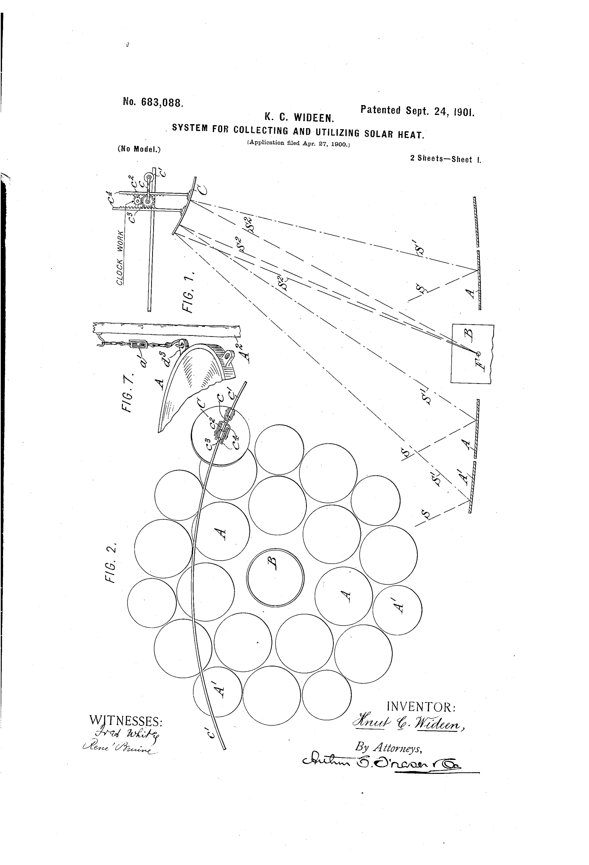
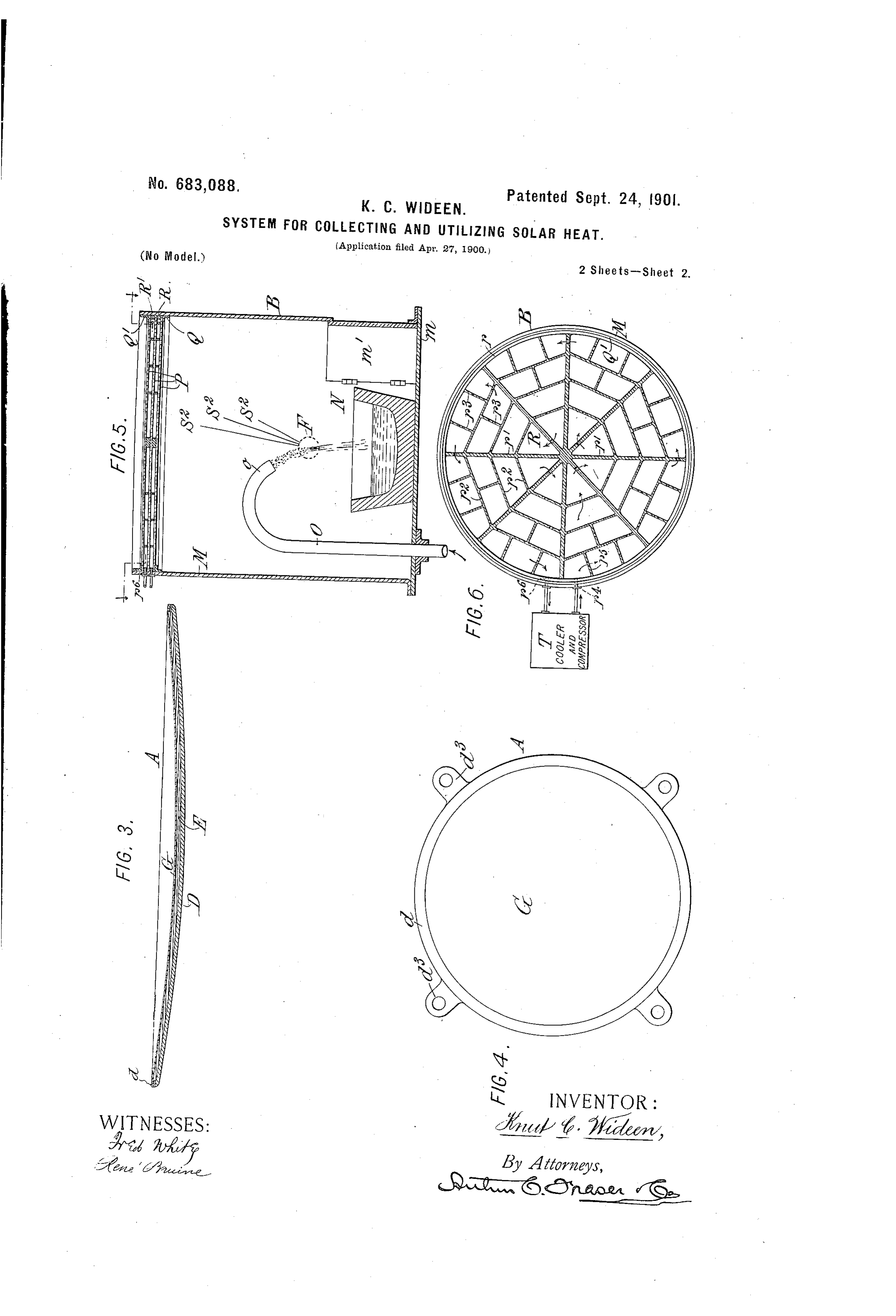
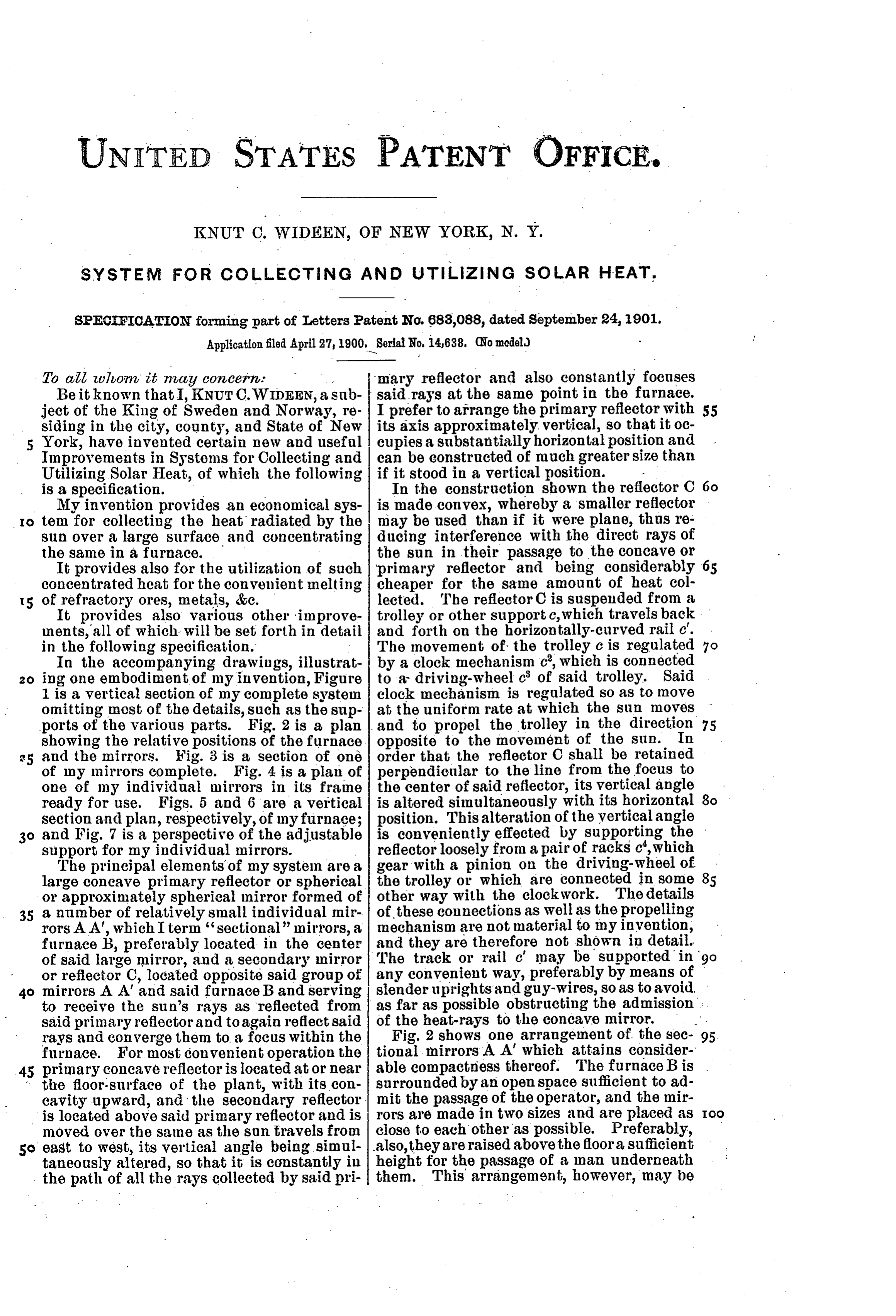
To all whom it may CO7 cer. r mary reflector and also constantly focuses Beit known that I, KNUTC.WIDEEN, a sub said rays at the same point in the furnace. ject of the King of Sweden and Norway, re I prefer to arrange the primary reflector with 55 siding in the city, county, and State of New its axis approximately, vertical, so that it oc York, have invented certain new and useful cupies a substantially horizontal position and Improvements in Systems for Collecting and can be constructed of much greater size than Utilizing Solar Heat, of which the following if it stood in a vertical position. is a specification. - In the construction shown the reflector C My invention provides an economical sys is made convex, whereby a smaller reflector IO tem for collecting the heat radiated by the may be used than if it were plane, thus re sun over a large surface and concentrating ducing interference with the direct rays of the same in a furnace. the sun in their passage to the concave or It provides also for the utilization of such primary reflector and being considerably 65 concentrated heat for the convenient melting cheaper for the same amount of heat col 5 of refractory ores, metals, &c. lected. The reflector C is suspended from a It provides also various other improve trolley or other support c, which travels back ments, all of which will be set forth in detail and forth on the horizontally-curved rail c. in the following specification. The movement of the trolley c is regulated o In the accompanying drawings, illustrat by a clock mechanism c, which is connected ing one embodiment of my invention, Figure to a driving-wheel c of said trolley. Said 1 is a vertical section of my complete system clock mechanism is regulated so as to move omitting most of the details, such as the sup at the uniform rate at which the sun moves ports of the various parts. Fig. 2 is a plan and to propel the trolley in the direction 75 showing the relative positions of the furnace. opposite to the movement of the sun. In and the mirrors. Fig. 3 is a section of one order that the reflector C shall be retained of my mirrors complete. Fig. 4 is a plan of perpendicular to the line from the focus to one of my individual mirrors in its frame the center of said reflector, its vertical angle ready for use. Figs. 5 and 6 are a vertical is altered simultaneously with its horizontal section and plan, respectively, of my furnace; position. This alteration of the vertical angle 30 and Fig. 7 is a perspective of the adjustable is conveniently effected by supporting the support for my individual mirrors. reflector loosely from a pair of racks c, which The principal elements of my system are a gear with a pinion on the driving-wheel of large concave primary reflector or spherical the trolley or which are connected in some 85 or approximately spherical mirror formed of other way with the clockwork. The details 35 a number of relatively small individual mir of these connections as well as the propelling rors AA, which Iterm “sectional' mirrors, a mechanism are not material to my invention, furnace B, preferably located in the center and they are therefore not shown in detail. of said large mirror, and a secondary mirror The track or rail c' may be supported in or reflector C, located opposite said group of any convenient way, preferably by means of 40 mirrors A A' and said furnace B and serving slender uprights and guy-wires, so as to avoid to receive the sun's rays as reflected from as far as possible obstructing the admission: said primary reflector and to again reflect said of the heat-rays to the concave mirror. rays and converge them to a focus within the Fig. 2 shows one arrangement of the sec 95. furnace. For most convenient operation the tional mirrors AA which attains consider primary concave reflectoris located at or near able compactness thereof. The furnace B is 45 the floor-surface of the plant, with its con surrounded by an open space sufficient to ad cavity upward, and the secondary reflector. mit the passage of the operator, and the mir IOO is located above said primary reflector and is rors are made in two sizes and are placed as moved over the same as the sun travels from close to each other as possible. Preferably, 50 east to West, its vertical angle being simul also, they are raised above the floor a sufficient taneously altered, so that it is constantly in height for the passage of a man underneath the path of all the rays collected by said pri them. This arrangement, however, may be
Page 4
considerably, varied and is shown only as ing in the process of manufacturing the one mode of arranging the parts. The track mirror.
c' is shown at approximately the position it G is the plate, of reflecting material-such would have in the northern part of this coun as silvered glass,celluloid, or polished metal o try and with the central radius of the large which forms the reflector proper. concave mirror standing in the vertical posi E is a backing, of stearin, rosin, lead, or tion. Each of the sectional mirrors A A', the like, which is filled into the chamber D by however, is adjustable in elevation and in a process set forth in my application for pat clination, so that by lowering those on one ent for improvements in curved mirrors and 75 o side and raising those on the other side of the apparatus and process for making the same, furnace the centralaxis may be changed from filed June 12, 1900, Serial No. 20,087. The the vertical to an inclined position to meet stearin or the like is quite hard, gives a firm the corresponding changes in the inclination backing to the mirror, and stiffens it in its of the sun due to the variation of the seasons, curved shape. Stearin is especially useful, or by changing equally all those at equal because of its slight expansion under heat distances from the center (using for a per and also its slight contraction in solidifying fectly accurate result sectional mirrors of and because it melts at a comparatively low the desired degree of curvature, as herein temperature (77 centigrade) and is about as after more fully explained) the degree of hard as wood when cold.
curvature may be regulated to correspond The curvature of my individual sectional with the distance to the secondary reflec reflectors is of approximately the same de tor C without altering the position of the gree as that of the complete reflector. Where axis of the reflected rays. As a means of ad the degree of curvature of the complete re justing the position of the sectional mirrors flector is adjusted through any considerable 25 I show a support A, from which said mirror range, that of the individual reflectors is depends, and an adjustable connection a' for changed to correspond there with by varying raising or lowering said mirror. It will be the quantity of backing material in the cham understood that there are four supports A ber. Where a normally solid backing ma for each mirror. The primary reflector hav terial, such as stearin, has been used, it will 95 ing its small segments A and A'arranged and of course require to be softened before being inclined as shown in Fig. 1 and the second diminished or increased in volume. With ary reflector C being also arranged as in Fig. normally liquid or semiliquid materials, how 1, the sun's rays S at all points of the primary ever, no preliminary softening is necessary. reflector are reflected upward, as shown at S', For example, by using air, water, or oil as O2 35 to the secondary reflector C, where they are the backing material and inserting plungers again reflected, as shown at S, and focused through the casting, which plungers may be at F in the furnace. It is apparent that by moved into or out of the body of the backing the use of a large primary reflector or, what material, I can-vary the volume of the ma is equivalent, by the use of a large number terial sufficiently to accomplish all the nec of seetional reflectors A A', set in such a rela essary variations in the degree of curvature tive position as to give practically one large of the reflector.
primary reflector, I can accumulate at the For the utilization of the high degree of point F so large a number of heat-rays as to heat generated in my system a special con intensify many times the heat of the sun in struction of furnace is advisable. Figs. 5 O 45 its ordinary diffused condition. I have, in and 6 show a furnaee especially adapted for fact, obtained with experimental systems a use in my system, which is designed to give sufficiently high temperature to fuse the most the maximum of strength with the minimum refractory, ores and pure metals. interference with the heat-rays and a most It is apparent that some of the advantages convenient means of introducing the mate II5 of my system might be obtained with the use rial to be fused. The furnace proper consists of a group of plane reflectors adjustable rela of a cylinder M, preferably of sheet metal, tively to each other so as to obtain a nearly spherical large reflector or that they might having a base m of the same material and a manhole in at one side thereof, the cover of be obtained by the use of a great number of which opens inward, so that the pressure small spherical sectional reflectors; yet it is within will assist in securing a tight closure 55 obviously advantageous to use curved mirrors for said manhole.
of considerable size. Such a mirroris shown F shows the focus of the rays SS as they in Figs. 3, 4, and 7. come from the secondary reflector C. D is a casting having a body portion cir N shows a pot or crucible, preferably of cular in outline and depressed at the center, highly refractory material, for receiving the I25 so as to form a segment of a sphere, and hav ore or metal.
ing a rim d projecting upward all around O is a pipe or tube for conveying the ores, such center portion, forming a chamber E. metals, or mixed materials which are to he . On the outside of the rim are formed a series passed through the focus F. Preferably the of perforated lugs d, used in attaching the upper end of said pipe is curved, as shown - mirror to its supports or in handling the cast at o, and bent downward, and the material
Page 5
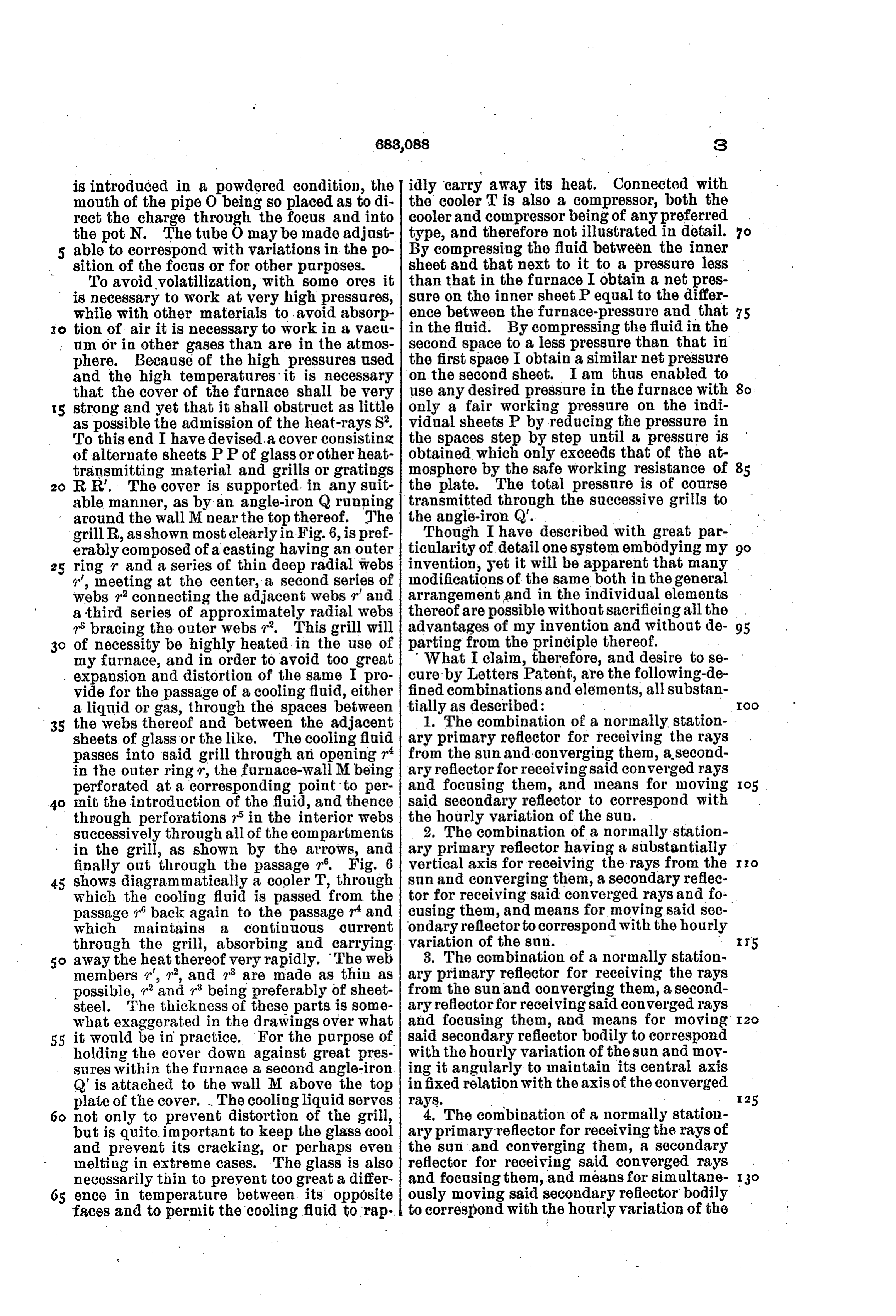
is introduced in a powdered condition, the idly carry away its heat. Connected with mouth of the pipe O being so placed as to di the cooler T is also a compressor, both the rect the charge through the focus and into coolerand compressor being of any preferred the pot N. The tube O may be made adjust type, and therefore not illustrated in detail. able to correspond with variations in the po By compressing the fluid between the inner sition of the focus or for other purposes. sheet and that next to it to a pressure less To avoid volatilization, with some ores it than that in the furnace I obtain a net pres is necessary to work at very high pressures, sure on the inner sheet P equal to the differ while with other materials to avoid absorp ence between the furnace-pressure and that 75 O tion of air it is necessary to work in a vacu in the fluid. By compressing the fluid in the um or in other gases than are in the atmos second space to a less pressure than that in phere. Because of the high pressures used the first space I obtain a similar net pressure and the high temperatures it is necessary on the second sheet. I am thus enabled to that the cover of the furnace shall be very use any desired pressure in the furnace with strong and yet that it shall obstruct as little only a fair working pressure on the indi as possible the admission of the heat-rays S. vidual sheets P by reducing the pressure in To this end I have devised a cover consisting the spaces step by step until a pressure is of alternate sheets PP of glass or other heat obtained which only exceeds that of the at transmitting material and grills or gratings mosphere by the safe working resistance of R. R. The cover is supported in any suit the plate. The total pressure is of course able manner, as by an angle-iron Q running transmitted through the successive grills to around the wall Mnear the top thereof. The the angle-iron Q'. .
grillR, as shown most clearly in Fig. 6, is pref Though I have described with great par erably composed of a casting having an outer ticularity of detail one system embodying my 90 25 ring r and a series of thin deep radial webs invention, yet it will be apparent that many r", meeting at the center, a second series of modifications of the same both in the general webs r connecting the adjacent webs rand arrangement and in the individual elements a third series of approximately radial webs thereofare possible without sacrificing all the r bracing the outer webs r. This grill will advantages of my invention and without de 95 of necessity be highly heated in the use of parting from the principle thereof. my furnace, and in order to avoid too great What I claim, therefore, and desire to se expansion and distortion of the same I pro cure by Letters Patent, are the following-de vide for the passage of a cooling fluid, either fined combinations and elements, all substan a liquid or gas, through the spaces between tially as described: - Ioo 35 the webs thereof and between the adjacent 1. The combination of a normally station sheets of glass or the like. The cooling fluid ary primary reflector for receiving the rays passes into said grill through ari opening r from the sun and converging them, a second in the outer ring r, the furnace-wall M being ary reflector for receiving said converged rays perforated at a corresponding point to per and focusing them, and means for moving 40 mit the introduction of the fluid, and thence said secondary reflector to correspond with through perforations r in the interior webs the hourly variation of the sun. successively through all of the compartments 2. The combination of a normally station in the grill, as shown by the arrows, and ary primary reflector having a substantially o finally out through the passage r. Fig. 6 vertical axis for receiving the rays from the 45 shows diagrammatically a cooler T, through sun and converging them, a secondary reflec which the cooling fluid is passed from the tor for receiving said converged rays and fo passage r back again to the passage rand cusing them, and means for moving said sec which maintains a continuous current ondary reflector to correspond with the hourly through the grill, absorbing and carrying variation of the sun. n away the heat thereof very rapidly. The web 3. The combination of a normally station members r", r, and r are made as thin as ary primary reflector for receiving the rays possible, rand r being preferably of sheet from the sun and converging them, a second steel. The thickness of these parts is some ary reflector for receiving said converged rays what exaggerated in the drawings over what and focusing them, and means for moving 55 it would be in practice. For the purpose of said secondary reflector bodily to correspond holding the cover down against great pres with the hourly variation of the sun and mov sures within the furnace a second angle-iron ing it angularly- to maintain its central axis Q is attached to the wall M above the top in fixed relation with the axis of the converged plate of the cover. The cooling liquid serves rays. v. I 25 not only to prevent distortion of the grill, 4. The combination of a normally station but is quite important to keep the glass cool ary primary reflector for receiving the rays of and prevent its cracking, or perhaps even the sun and converging them, a secondary melting in extreme cases. The glass is also reflector for receiving said converged rays necessarily thin to prevent too great a differ and focusing them, and means for simultane 65 ence in temperature between its opposite ously moving said secondary reflector bodily faces and to permit the cooling fluid to rap to correspond with the hourly variation of the
Page 6
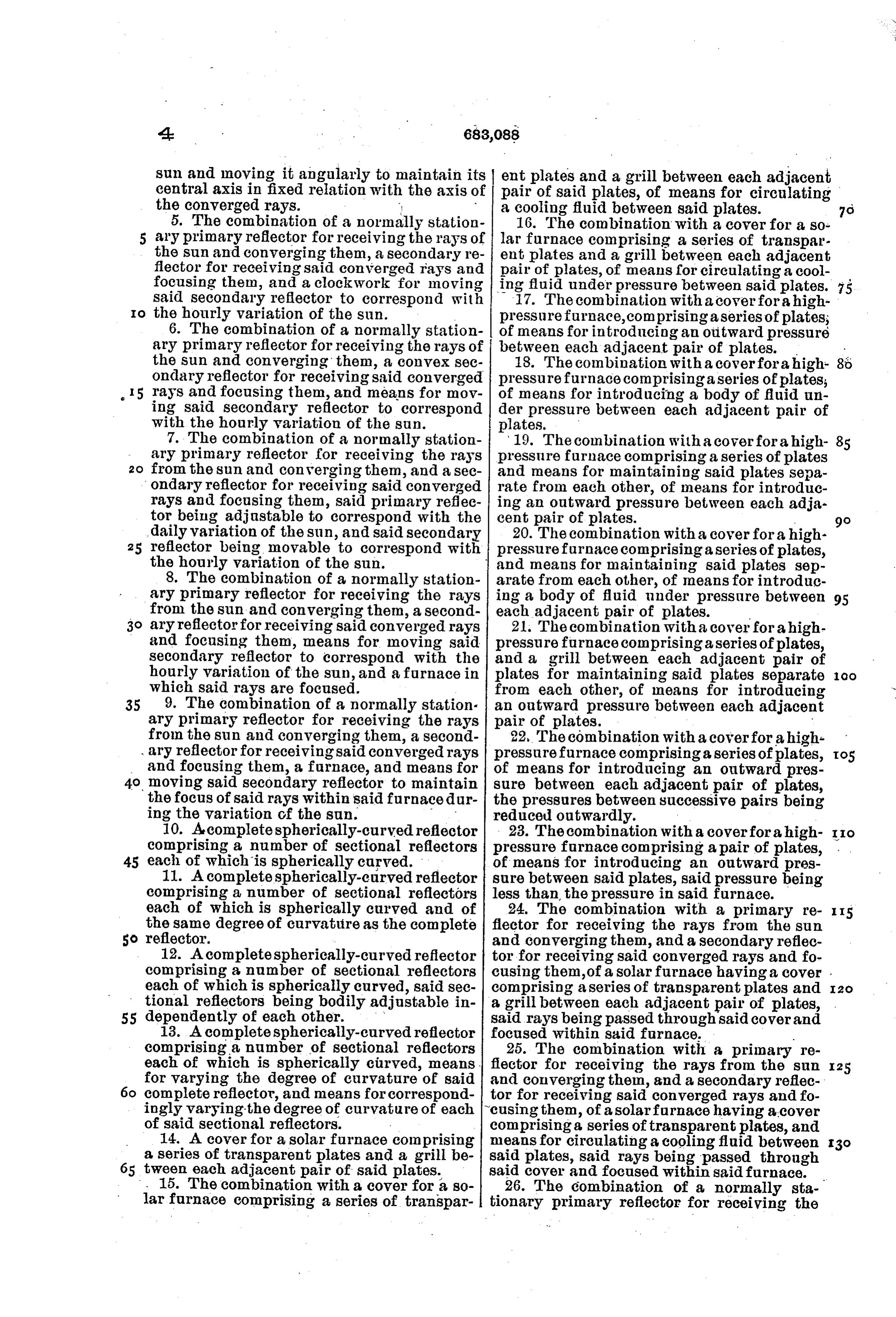
sun and moving it angularly to maintain its ent plates and a grill between each adjacent central axis in fixed relation with the axis of pair of said plates, of means for circulating the converged rays. a cooling fluid between said plates. 5. The combination of a normally station 16. The combination with a cover for a so ary primary reflector for receiving the rays of lar furnace comprising a series of transpar the sun and converging them, a secondary re ent plates and a grill between each adjacent flector for receiving said converged rays and pair of plates, of means for circulating a cool focusing them, and a clockwork for moving ing fluid under pressure between said plates. 75 said secondary reflector to correspond with 17. The combination with a cover for a high O the hourly variation of the sun. pressure furnace, comprising a series of plates, 6. The combination of a normally station of means for introducing an outward pressure ary primary reflector for receiving the rays of between each adjacent pair of plates. the Sun and converging them, a convex sec 18. The combination with a cover for a high 86 ondary reflector for receiving said converged pressure furnace comprising a series of plates; 15 rays and focusing them, and means for mov of means for introducing a body of fluid un ing said secondary reflector to correspond der pressure between each adjacent pair of with the hourly variation of the sun. plates.
7. The combination of a normally station 19. The combination with a cover for a high ary primary reflector for receiving the rays pressure furnace comprising a series of plates from the sun and converging them, and a sec and means for maintaining said plates sepa ondary reflector for receiving said converged rate from each other, of means for introduc rays and focusing them, said primary reflec ing an outward pressure between each adja tor being adjustable to correspond with the cent pair of plates.
daily variation of the sun, and said secondary 20. The combination with a cover for a high reflector being movable to correspond with pressure furnace comprising a series of plates, the hourly variation of the sun. and means for maintaining said plates sep 8. The combination of a normally station arate from each other, of means for introduc ary primary reflector for receiving the rays ing a body of fluid under pressure between 95 from the sun and converging them, a second each adjacent pair of plates.
3o ary reflector for receiving said converged rays 21. The combination with a cover for a high and focusing them, means for moving said pressure furnace comprising a series of plates, secondary reflector to correspond with the and a grill between each adjacent pair of hourly variation of the sun, and a furnace in plates for maintaining said plates separate OO which said rays are focused. from each other, of means for introducing 35 9. The combination of a normally station an outward pressure between each adjacent ary primary reflector for receiving the rays pair of plates.
from the sun and converging them, a second 22, The combination with a coverfor a high ary reflector for receiving said converged rays pressure furnace comprising a series of plates, and focusing them, a furnace, and means for of means for introducing an outward pres moving said secondary reflector to maintain sure between each adjacent pair of plates, the focus of said rays within said furnace dur the pressures between successive pairs being ing the variation of the sun. - reduced outwardly.
10. A complete spherically-curved reflector 23. The combination with a coverfor a high O comprising a number of sectional reflectors pressure furnace comprising a pair of plates, 45 each of which is spherically curved. of means for introducing an outward pres 11. A complete spherically-curved reflector sure between said plates, said pressure being comprising a number of sectional reflectors less than the pressure in said furnace. each of which is spherically curved and of 24. The combination with a primary re II5 the same degree of curvatuire as the complete flector for receiving the rays from the sun So reflector. - and converging them, and a secondary reflec 12. A complete spherically-curved reflector tor for receiving said converged rays and fo comprising a number of sectional reflectors cusing them, of a solar furnace having a cover . each of which is spherically curved, said sec comprising a series of transparent plates and 120 tional reflectors being bodily adjustable in a grill between each adjacent pair of plates, 55 dependently of each other. - said rays being passed through said cover and 13. A complete spherically-curved reflector focused within said furnace.
comprising a number of sectional reflectors 25. The combination with a primary re each of which is spherically cturved, means. flector for receiving the rays from the sun for varying the degree of curvature of said and converging them, and a secondary reflec I25 complete reflector, and means for correspond tor for receiving said converged rays and fo ingly varying the degree of curvature of each cusing them, of a solarfurnace having a cover of said sectional reflectors. comprising a series of transparent plates, and 14. A cover for a solar furnace comprising means for circulating a cooling fluid between a series of transparent plates and a grill be said plates, said rays being passed through tween each adjacent pair of said plates. said cover and focused within said furnace. . 15. The combination with a cover for a so 26. The combination of a normally sta lar furnace comprising a series of transpar tionary primary reflector for receiving the
Page 7
rays from the sun and converging them, a cusing them, a furnace, and means for mov secondary reflector for receiving said con ing said secondary reflector bodily so as to I5 verged rays and focusing them, a furnace, constantly receive said converged rays and and means for moving said secondary reflec angularly so as to constantly focus said rays Y
tor bodily so as to constantly receive said within said furnace. - converged rays and angularly so as to con In witness whereof I have hereunto signed stantly focus said rays within said furnace. my name in the presence of two subscribing 20 27. The combination of a normally sta witnesses.
tionary primary reflector having a substan KNUT. C. WIDEEN. O tially vertical axis, for receiving the rays from the sun and converging them, a secondary Witnesses: . s reflector arranged above said primary reflec THOMAS F. WALLACE, tor, for receiving said converged rays andfo FRED WHITE.

Provenance
- Collection
- Cited prior art
- Original PDF
- patentimages.storage.googleapis.com →
- Filed
- 1900-04-27
- Pages
- 7
- Method
- pdftotext (the PDF's own text layer) + pdftoppm 300dpi page scans
- Source
- Google Patents bibliographic record
- Granted
- 1901-09-24
- Inventors
- Knut C Wideen
- Transcribed from
- patentimages.storage.googleapis.com →