patent · US3182654
Solar energy heating apparatus
11 May 1965
Page 1
Drawing sheet — no readable text.
Page 2
United States Patent Office 3,182,654 Patented May 11, 1965
ing. The internal pressure may be maintained by an air 3,182,654 blower 5 adapted to maintain the desired internal pres
SOLAR ENERGY HEATING APPARATUS sure even in the presence of seam leaks, small ventilation John H. Culing, Kirkwood, Mo., assignor to Carondelet ports, windows, or doors. The air blower 5 is mounted Foundry Compasay, St. Louis, Mo., a corporation of on entrance 3. A pneumatic structure of this type is well Missouri
Filed Aug. 25, 1960, Ser. No. 5,846 known, particularly as used for housing radar and other 6 Claims. (C. 26-270) defense equipment in arctic or subarctic areas.
The entrance 3 has an outer door 7 and an inner door
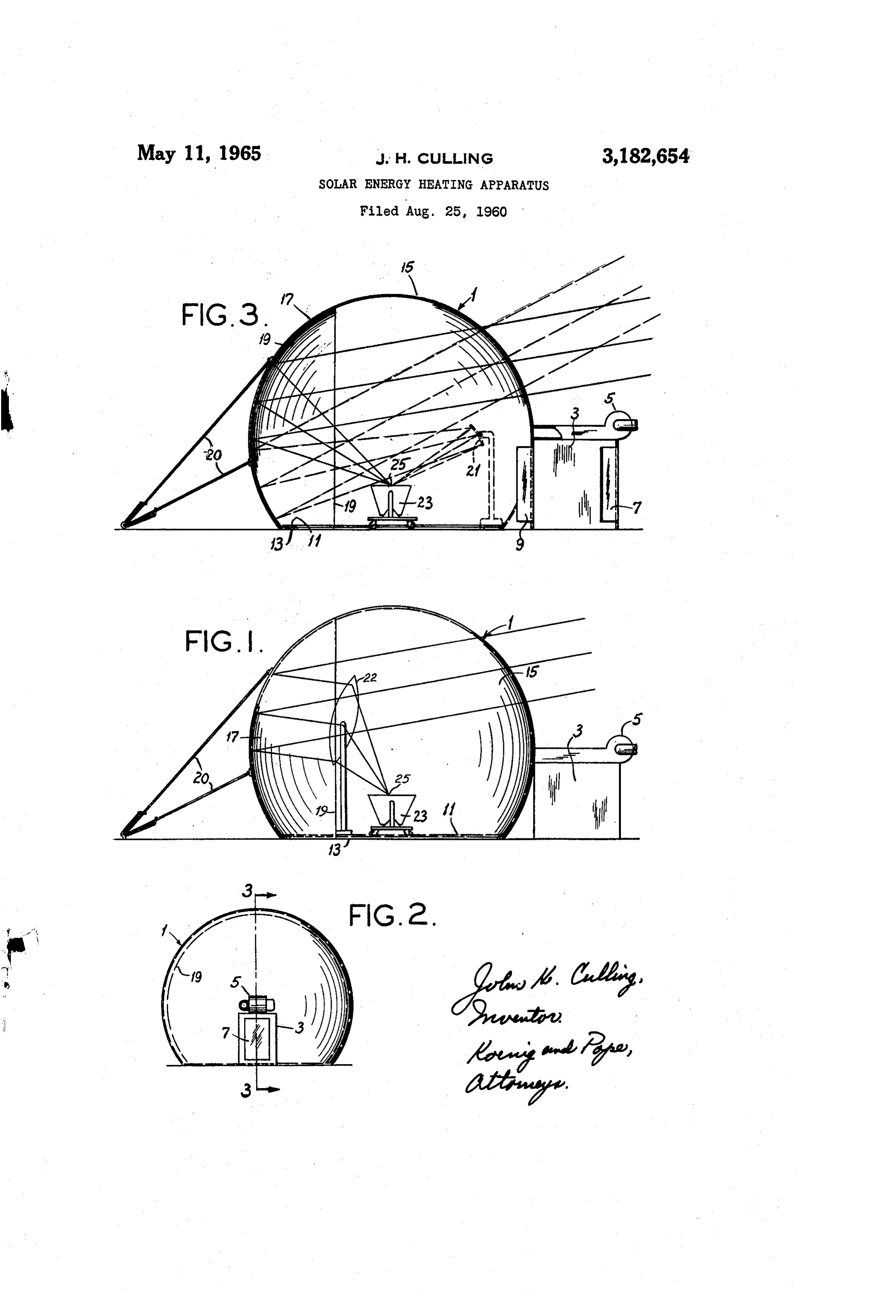
This invention relates to solar energy heating apparatus, 9, both of which open inwardly. By the use of these and more particularly to a solar energy heating apparatus 10 doors 7 and 9, an air lock is formed within entrance 3 for concentrating solar energy on a very small area for to provide for the entrance and exit of operating person such useful purposes as melting, baking, storing of heat, nel and for the transportation of materials or equipment or any other purpose in which a high temperature is re in and out of the housing without substantial deflation quired. thereof. Any convenient anchoring means may be used Heretofore, solar energy heating apparatus, and par 15 to secure the housing to the ground. For example, a rigid ticularly solar energy heating apparatus or furnaces suit ring 11 made of a heavy material, such as steel, may rest able for concentrating solar energy rays on a very small on the bottom portion 13 of housing 1. area, were relatively expensive to construct due to the A portion of the housing is indicated at reference nu high cost of a reflector adapted to concentrate solar en meral 5. Portion 15 is substantially transparent and is ergy, such as a parabolic mirror or a polished metal re 20 adapted to transmit solar energy rays. Another portion flector, and the rigid supporting structure for these reflec- . of the housing is indicated at reference numeral 17 and is tors. These solar energy heating apparatus or furnaces provided on the internal surface thereof with a material were, by the nature of their construction and use, exposed 9 adapted to reflect solar energy. Such material 19 may to rain, dust, Snow, and other elements detrimental to be a coating of metallic or other reflecting fabric, cloth, their operation. Being of a rigid construction, these solar 25 paint, or any other material adapted to reflect solar en furnaces were not adapted for use in areas where earth ergy. The portion 17 of the housing and the reflective quakes, windstorms, or other hazardous conditions might material 19 on the internal side thereof may be of a develop. paraboloidal, spherical, or ellipsoidal shape, or of some - Accordingly, among the several objects of this inven other suitable shape that concentrates radiant energy. tion may be noted the provision of a solar energy heating 30 The desired shape of portion 17 and reflective material 19 apparatus having a pneumatic structure protecting the re may be obtained by molding them to such shape or by flecting surface or surfaces from damaging weather ele the use of guy wires (such as indicated at 20) attached ments and at the same time providing a shelter for acces to the outside of portion 17 and anchored to the ground. sory equipment and operating personnel; the provision of Solar energy rays pass through portion 15 and strike a solar energy heating apparatus having its own housing the reflector 19. These rays may then be directed and structure in a form suitable for quick deflation and trans concentrated toward a small area 25, at which a focus of portation; the provision of a solar energy heating appa the solar energy rays is formed, as shown by the solid ratus having an inflatable housing, one portion of which lines in FIG. 3; or they may be directed and concentrated is adapted to transmit solar energy and a second portion toward a planar or corrective reflector 21 which further of which is adapted to reflect and concentrate solar energy 40 directs and concentrates the solar energy rays to a focus transmitted through the first portion toward an interior (shown in FIG. 3 to be at area 25), as shown by dotted region of the housing; and the provision of a solar energy lines in FIG. 3; or they may be directed and concentrated heating apparatus which is of a simplified and economical on area 25 by a lens 22 after reflection from reflector 19 construction and reliable in operation. Other objects and as shown by the solid ray lines in FIG. 1. features will be in part apparent and in part pointed out The object or material on which the radiant energy is hereinafter. to be concentrated is placed on a movable carrier 23. The invention accordingly comprises the constructions The focus point of the radiant energy will be constantly changing, since the angle at which the radiant energy hereinafter described, the scope of the invention being in dicated in the following claims. strikes the reflector will be changing as a result of the In the accompanying drawings, in which several of 50 relative movement between the earth and the sun. Ac various possible embodiments of the invention are illus cordingly, when the radiant energy is directly transmitted trated, from the reflector 9 without the use of a secondary re FIG. 1 is a side view in elevation of a solar energy flector 2 or lens 22, the carrier 23 must be moved by the heating apparatus of this invention; operating personnel or automatically by any conven FIG. 2 is a front view of FIG. 1; and tional controlled movement device to keep the radiant F.G. 3 is a vertical section taken on line 3-3 of FIG. energy focused on the object or material, or alternately 2, showing two methods of use of the solar energy heating the reflective surface 19 may be altered to maintain the apparatus. focus of the radiant energy on carrier 23, for example Corresponding reference characters indicate corre by adjusting the guy wires 20.
sponding parts throughout the several views of the draw 60 When the secondary reflector 21 and/or a lens 22 is lingS. used, it may be moved manually or automatically so as Referring to the drawings, a solar energy heating appa to direct and concentrate the solar energy rays towards ratus of the present invention is shown to comprise a a stationary point and the carrier 23 and object or mate housing 1 having an entrance 3. The housing is a rela rial carried thereby may remain fixed at that point. tively air-tight flexible dome-like or tent-like structure 65 The lens 22 could be placed in the path of the rays fabricated, for example, from any customary synethetic reflected by reflector 21 or it could be placed in the path resin plastic material. The flexible dome-like or tent-like of the solar energy rays reflected by reflector 19, as shown configuration is maintained by having the internal air in F.G. 1.
pressure slightly in excess of the surrounding or atmos If it is desired to melt a metal, for example, it may be pheric pressure. An internal pressure of a few ounces 70 done in several ways. One way is for the operating per above atmospheric pressure is sufficient to prevent col sonnel to place the metal in a cupola on carrier 23. The lapse or substantial deformation of the pneumatic hous carrier is then placed so that the solar energy rays are
Page 3
initially focused on the cupola. The carrier 23 is then 3. A solar energy heating apparatus as defined in moved from time to time as the point of focus of the solar claim 1 wherein said means comprises a lens. energy changes during the period in which the melting 4. A solar energy heating apparatus comprising an in process occurs. Also, the metal in a cupola on the car flatable tent-like structure for housing personnel, blower rier 23 may be situated in any convenient fixed location neans for maintaining the air pressure within said struc within the housing 15 in such a position that solar energy ture greater than the air pressure outside said structure rays reflected from reflector 19 either fall directly on the thereby to support the structure, a first portion of said cupola, or fall on reflector 2 or lens 22 and are directed structure being adapted to transmit solar energy, a sec and concentrated therefrom toward and upon the cupola. ond portion having a reflector adapted to reflect and con At the focus point of the solar energy rays changes, the 0. centrate solar energy transmitted through said first por shape of reflector 19 is modified, for example, by changing tion toyard an object within said structure, and a second the tension in the guy wires so as to maintain the focus of reflector for maintaining the solar energy focused on said the Solar energy rays on the cupola or on the reflector 21 object as the sun moves relative to the structure. or lens 22; or the reflector or lens may be moved so as to 5. A solar energy heating apparatus comprising an in direct and concentrate the energy rays received from flatable tent-like structure for housing personnel, means reflector 19 toward the stationary cupola. for inflating the structure to cause the latter to assume a This invention is particularly adapted for use in areas, dome-like configuration, a first portion of said structure such as mountainous or remote locations, where the con being adapted to transmit solar energy, a second portion struction of solar energy heating apparatus requiring of said structure being adapted to reflect and concentrate rigid and complex structures would be costly, if at all 20 Solar energy transmitted through said first portion to possible. It is further contemplated that this solar energy ward an object within said structure, an air lock for entry heating apparatus might be used in cold climate areas for and exit of personnel without loss of inflation, and means heating purposes through the employment of a heat sink connected to said structure for anchoring the latter against body. The concentrated solar energy could be stored in substantial movement.
a radiator body or similar device during the hours in 6. A solar energy heating apparatus comprising an in which solar energy is abundant, and slowly released to flatable tent-like structure for housing personnel, blower Supply heating during the hours in which solar energy means for maintaining the air pressure within said struc is limited or absent. ture greater than the air pressure outside said structure In view of the above, it will be seen that the several ob thereby to support the structure, a first portion of said jects of the invention are achieved and other advantageous 30 structure being adapted to transmit solar energy, a second results attained. portion having a reflector adapted to reflect and concen As various changes could be made in the above con trate solar energy transmitted through said first portion structions without departing from the scope of the inven toward an object within said structure, and a lens for tion, it is intended that all matter contained in the above maintaining the solar energy focused on said object as descripion or shown in the accompanying drawings shall 35 the Sun moves relative to the structure. be interpreted as illustrative and not in a limiting sense. References Cited by the Examiner I claim:
1. A solar energy heating apparatus comprising an UNITED STATES PATENTS inflatable tent-like structure for housing personnel, a first 683,088 9/01 Wideen -------------- 126-270 portion of said structure being adapted to transmit solar 40 1,302,182 4/19 Lanchester ------------- 136-1 energy, a second portion having a reflector integrally at 1,880,938 10/32 Emmet -------------- 126-271 tached to the interior surface of said second portion, and 2,291,534 7/42. Deppe ------------ 126-270 X means within said structure adapted to concentrate solar 2,649,101 8/53 Suits ------------------- 135-1 energy directed thereon toward an object within said 2,785,695 3/57 Carey ---------------- 135-1 structure, said reflector being adapted to reflect solar 45 2,872,915 2/59 Bowen --------------- 126-271 energy transmitted through said first portion toward said 3,029,596 4/62 Hanold et al. -------- 126-270 X means, said means being movable to receive said solar 3,054,328 9/62 Rodgers ----------- 126-270 X energy from Said reflector as the sun moves relative to the 3,125,091 3/64 Sleeper --------------- 126-271 Structure.
2. A solar energy heating apparatus as defined in claim 50 JAMES W. WESTHAVER, Primary Examiner. 1 wherein said means comprises a second reflector. PERCY L. PATRICK, Examiner.
Provenance
- Collection
- Cited prior art
- Original PDF
- patentimages.storage.googleapis.com →
- Filed
- 1960-08-25
- Pages
- 3
- Method
- pdftotext (the PDF's own text layer) + pdftoppm 300dpi page scans
- Source
- Google Patents bibliographic record
- Granted
- 1965-05-11
- Inventors
- John H Culling; Carondelet Foundry Co
- Transcribed from
- patentimages.storage.googleapis.com →