patent · US5057162
Thermophotovoltaic technology
15 October 1991
Page 1 — bibliographic record
United States Patent (19) 11) Patent Number: '5,057,162 Nelson (45) Date of Patent: Oct. 15, 1991 54) THERMOPHOTOVOLTAICTECHNOLOGY Journal of the Franklin Institute, vol. 186, No. 11 14-33, (75 Inventor: Robert E. Nelson, Weston, Mass. pp. 401-625 (1918).
White et al., "P-I-N" Strutures for Controlled Spec 73) Assignee: TPV Energy Systems, Inc., Waltham, trum Photovoltaic Converters, Advisory Group for Mass. Aerospace Research and Development, North Atlantic *) Notice: The portion of the term of this patent Treaty Organization, pp. 897-922. subsequent to Apr. 22, 2003 has been White, "Diffuse-reflectance Spectra of Rare-Earth disclaimed. Oxides", Applied Spectroscopy, vol. 21, No. 3, pp. (21) Appl. No.: 606,527 167-171 (1967).
Durand, "Performance Characteristics of High Tem 22 Filed: Oct. 31, 1990 perature Gas-Fired Mantle Systems', Technical report
Related U.S. Application Data Kittlet al., "Design Analysis of TPV-Generator Sys 60 Division of Ser. No. 344,695, Apr. 28, 1989, Pat. No. tem', Proc., 25th Annual Power Sources Conf, (1972). 4,976,606, which is a continuation of Ser. No. 168,458, Guazzoni, "High-Temperature Spectral Emittance of Mar. 15, 1988, Pat. No. 4,826,426, which is a division of Oxides of Erbium, Samarium, Neodymium and Ytter Ser. No. 815,888, Jan. 3, 1986, Pat. No. 4,764,104, bium', Applied Spectroscopy, vol. 26, No. 1, pp. 60-65 which is a division of Ser. No. 634,379, Jul. 3, 1984, (1972).
Pat. No. 4,584,426, which is a continuation-in-part of Guazzoni et al., "Cylindrical Erbium Oxides Radiator Ser. No. 529,016, Sep. 2, 1983, abandoned. Structures for Thermophotovoltaic Generators', R & 51) Int. Cl. ........................................... HOL 31/O58 D Technical Report ECOM-4249, pp. 1-27 (1974). 52 ... 136/253 58) Field of Search ......................................... 136/253 Primary Examiner-Aaron Weisstuch Attorney, Agent, or Firm-Fish & Richardson
3,33,707 7/1967 Warth ................................. 136/253 A high-output, narrow band thermally energized radia 3,751,303 8/1973 Kittl .................................... 136/253 tion source comprises a rare earth oxide radiator men 3,929,510 12/1975 Kitti .................................... 136/247 ber that has a cross-sectional dimension in the range of 4,234,352 ll/1980 Swanson ............................. 136/253 five to thirty micrometers, the rare earth oxide radiator 4,313,024 1/1982 Horne .................................. 136/253 member, when heated to about 1700 C., having a con 4,584,426 4/1986 Nelson ................................ 136/253 centrated radiated flux over the 400-2500 nanometer 4,764,104 8/1988 Nelson ................................ 431/100 4,793,799 12/1988 Goldstein ... 431/79 wavelength range such that at least 50% of the radiated 4,976,606 12/1990 Nelson ..... 431/79 flux is within a spectral band that is less than 400 nano meters wide.
OTHER PUBLICATIONS
Ives et al. "A Physical Study of the Welsbach Mantle', 15 Claims, 2 Drawing Sheets
CONTROL

Page 2
Drawing sheet — no readable text.
Page 3
Drawing sheet — no readable text.
Page 4
Welsbach mantles have been proposed for use in ther
THERMOPHOTOVOLTAC TECHNOLOGY mophotovoltaic energy conversion systems, such uses are not particularly efficient as such mantles generate
This is a divisional of application Ser. No. substantial amounts of radiation throughout a spectral 07/344,695, filed Apr. 28, 1989, now U.S. Pat. No. 5 region that extends from the visible well into the infra 4,976,606, which is a continuation of application Ser. red. Other proposed thermophotovoltaic energy con No. 07/168,458, filed Mar. 15, 1988, which is a divi version systems have used reflector and rare earth ac sional of U.S. Ser. No. 06/815,888, filed Jan. 3, 1986, tive filter arrangements.
now U.S. Pat. No. 4,764,104, which is a divisional of In accordance with one aspect of the invention, the U.S. Ser. No. 06/634,379, filed July 31, 1984, now U.S. 10 rare earth oxide radiator member of the narrow band Pat. No. 4,584,426, which is a continuation-in-part of thermally energized radiation source has a cross-sec now abandoned U.S. Ser. No. 06/529,016, filed Sept.2, tional dimension in the range of five to thirty microme 1983. ters, and that rare earth oxide radiator member, when This invention relates to radiation sources and more heated to about 1700 C., has a concentrated radiated particularly to sources of the thermally excited type in S flux over the 400-2500 nanometer wavelength range which radiation is emitted from a heated element, and to such that at least 50% of the radiated flux is within a thermophotovoltaic devices. spectral band that is less than 400 nanometers wide. The Radiation sources of the thermally excited type such radiation source may be thermally excited by various as incandescent lamps in which light is emitted from a techniques including, for example, electrical energy or highly heated resistance wire and incandescent mantles liquid or gaseous fuels such as hydrogen, natural gas, of the Welsbach type have long been known. Such propane, butane, isobutane or gasoline.
radiation sources generally have characteristics of the In preferred embodiments, the narrow band ther "black body', or more realistically "gray body', type mally excited radiation source is composed of inter and emit radiation over a broad spectral band. In accor locked fibers of at least one oxide of a host rare earth dance with one aspect of the invention, there is pro 25 metal selected from a class consisting of erbium, hol vided a thermally excited radiation source that has a mium, neodymium and ytterbium, the radiated flux of narrow peak in the spectral profile of its radiated flux the radiation source having a full width at half maxi and skirt portions of the radiated flux profile on either mum (at the maximum radiated flux of the source) of side of the narrow peak are suppressed so that the emit less than 400 nanometers. The relative spectral irradi ted radiation has a concentrated spectral distribution. 30 ance profiles of preferred radiators also have suppressed Such a thermally excited narrow band radiation skirt characteristics such that at wavelengths 500 nano source may have a variety of applications and, for ex meters above and below the peak wavelength, the skirts ample, may usefully be coupled to a photovoltaic cell to have radiated fluxes that are less than ten and more provide a thermophotovoltaic device. Radiation that is preferably less than five percent of the profile peak absorbed by a photovoltaic cell in the neighborhood of 35 radiated flux. In particular embodiments, the radiation a potential barrier, usually a pn junction, gives rise to source is a self-supporting rare earth oxide fiber mantle separated electron-hole pairs which create an electric that defines a hollow space, and that is secured on a potential. The photocell conversion efficiency is a func support tube by an integral shrunken skirt portion. tion of the band gap (in electron volts) and the tempera In accordance with another aspect of the invention ture of the particular photocell material. Among the 40 there is provided a thermophotovoltaic device that known types of photocell material are silicon, which includes a photocell and a radiator of rare earth metal has a band gap of about 1.1 electron volts, equivalent to oxide material disposed in optically coupled relation to a wavelength of about 1150 nanometers; and germa the photocell. Such thermophotovoltaic devices may be nium, which has a band gap of about 0.7 electron volt, used in power generation, topping cycles, cogeneration, equivalent to a wavelength of about 1800 nanometers. or communication applications, for example. The radia In a thermophotovoltaic device, a close match between tor and photocell may be close coupled, for example in the spectrum of photon energy radiated from the radia the same housing, or spaced apart with the radiation tion source and the electron production threshold of the from the radiator focused on the more remotely located photovoltaic cell results in a greater amount of energy photocell, or coupled as by means offiber optic technol which is absorbed by the photovoltaic cell being con 50 ogy. The thermophotovoltaic device also includes verted to electrical energy and a minimal amount being means for thermally exciting the radiator to cause it to converted to heat. Silicon photovoltaic cells have rela emit radiation in a spectral irradiance profile that has a tively low conversion efficiency in direct sunlight, in radiated flux peak with a full width at half maximum of part because the specific spectral energy of solar radia less than 400 nanometers, the radiated flux peak being tion does not provide a good spectral match with the 55 less than 400 nanometers below (on the higher energy response of a silicon photovoltaic cell as that portion of side of) the electron production threshold of the photo solar radiation with wavelengths longer than 1100 cell. The photon conversion efficiency of preferred nanometers is useless to the silicon cell photovoltaic thermophotovoltaic devices is more than fifty percent. conversion process and generates heat in the cell requir In accordance with still another aspect of the inven ing an increased effort for cooling to keep the cell at its 60 tion a radiator of rare earth metal oxide material is ther best performance, and as the maximum spectral radi mally excited at a temperature in the range of ance in sunlight occurs at about 500 nanometers which 1500-2000 C. to cause the radiator to emit radiation in corresponds to a photon energy of 2.5 electron volts, a spectral irradiance profile that has a narrow radiated while only 1.1 electron volts are required to produce flux peak that has a full width at half maximum of less the hole-electron pairs in silicon which contribute to 65 than 400 nanometers and preferably less than 200 nano external current flow and power output. The surplus meters, and suppressed skirt characteristics such that at energy of photons in the spectral region below 1100 wavelengths in the range of 300-500 nanometers above nanometers is also converted to heat in the cell. While and below the flux peak, the radiated flux levels of the
Page 5
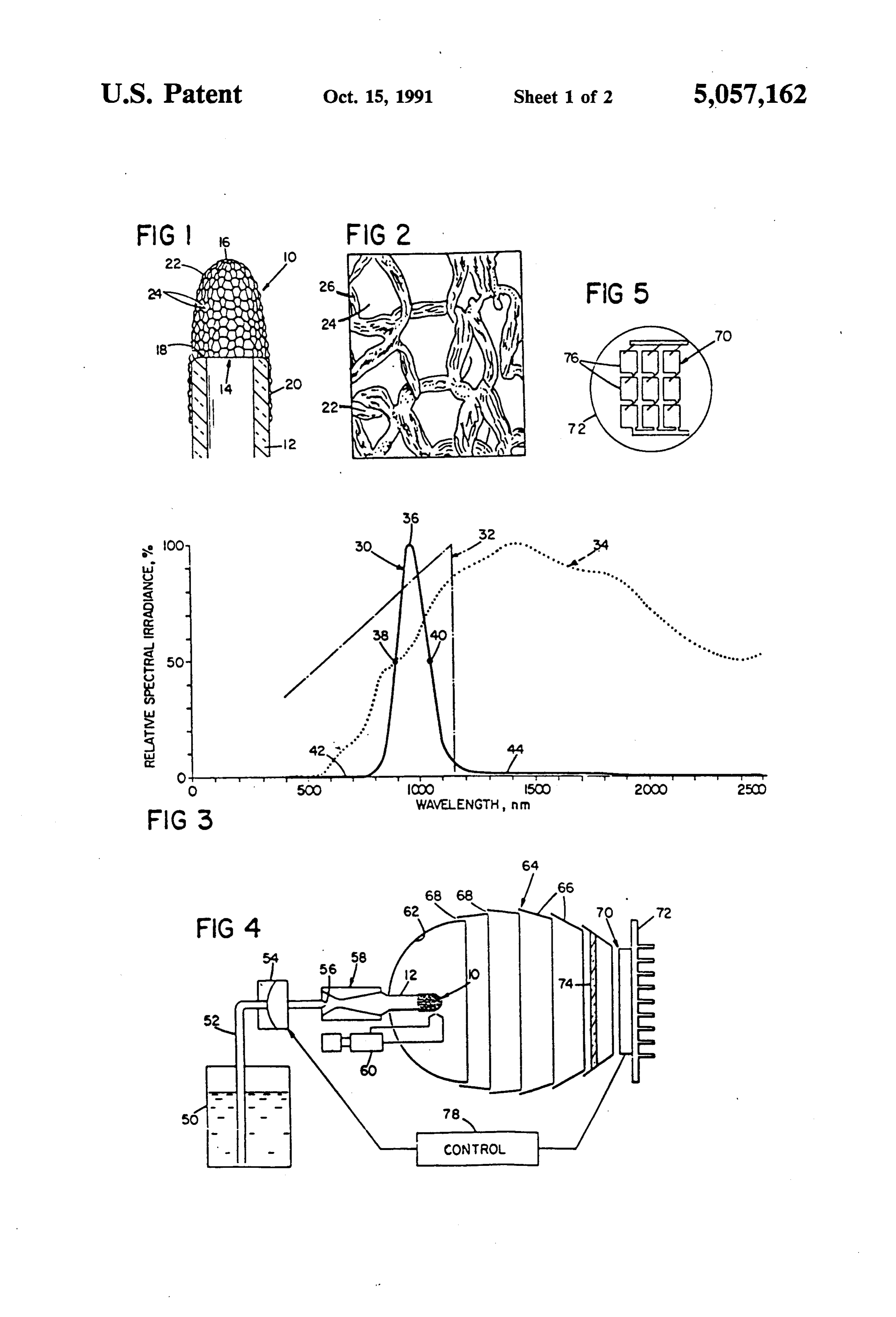
skirts are less than ten and preferably less than five millimeters and an inner diameter of about three milli percent of the peak radiated flux. meters. Mantle 10 is a self-supporting ytterbia fiber In particular thermophotovoltaic device embodi fabric structure that defines a hollow chamber 14 of ments, the thermal excitation system includes a liquid about seventy cubic millimeters volume with tip 16 hydrocarbon fuel supply, a conduit connected to the 5 about centimeter above the upper end surface 18 of fuel supply that has an outlet port aligned with the rare support tube 12. The lower portion 20 of the mantle earth metal oxide radiator, a fuel control for controlling fabric is about centimeter in length and is firmly the flow of fuel through the conduit to the radiator, and shrink-secured to the outer surface of support tube 12. an igniter mechanism for igniting the fuel. Particular The mantle fabric is formed of ytterbia multi-filament radiators are self-supporting rare earth metal oxide fiber O strands 22 in an open knit array with openings 24 such mantles that are composed of metal oxide multi-filament that the open area of the fabric is about 60%. The cross strands with cross-sectional strand dimensions in the sectional dimensions of the individual ytterbia filaments range of 0.05-0.3 millimeter and filament cross-sectional 26 (FIG. 2) of strands 22 are in the range of about five dimensions in the range of five to thirty micrometers A ten micrometers, and the strands 22 have cross-sectional reflector system may advantageously be employed for 15 dimensions in the order of about 0.1 millimeter with collecting, directing and concentrating the radiated flux openings 24 having dimensions of about 0.5 millimeter. from the mantle to the photocell, and radiation trans A process for manufacturing mantle 10 is as follows. mitting thermal isolation structure may be positioned Continuous low twist, low tenacity (highly reticulated), between the mantle (or mantles) of the radiation source viscose rayon yarn (150 denier/60 filament) is knitted and the photovoltaic cell array. Particularly useful ther 20 into a continuous tubular sleeve using a Lamb circular mophotovoltaic devices include anytterbia mantle cou string knitter (Model ST3A/ZA) with a 2.2 centimeter pled to a silicon type photocell and an erbia mantle diameter arbor and 24 needle capacity using 12 equally coupled to a germanium type photocell. spaced needles in the arbor. The yarn is knitted into a Mantle arrangements such as multiple mantles or continuous tubular sleeve with tension on both the yarn mantles of more complex geometry such as pleated 25 and the knitted sleeve to attain about-three stitches per structures that are designed to radiate more energy linear centimeter of tensioned sleeve, and the continu without a corresponding increase in convection loss ous length of knitted sleeve is wound onto a take-up may also be employed in thermophotovoltaic devices in spool.
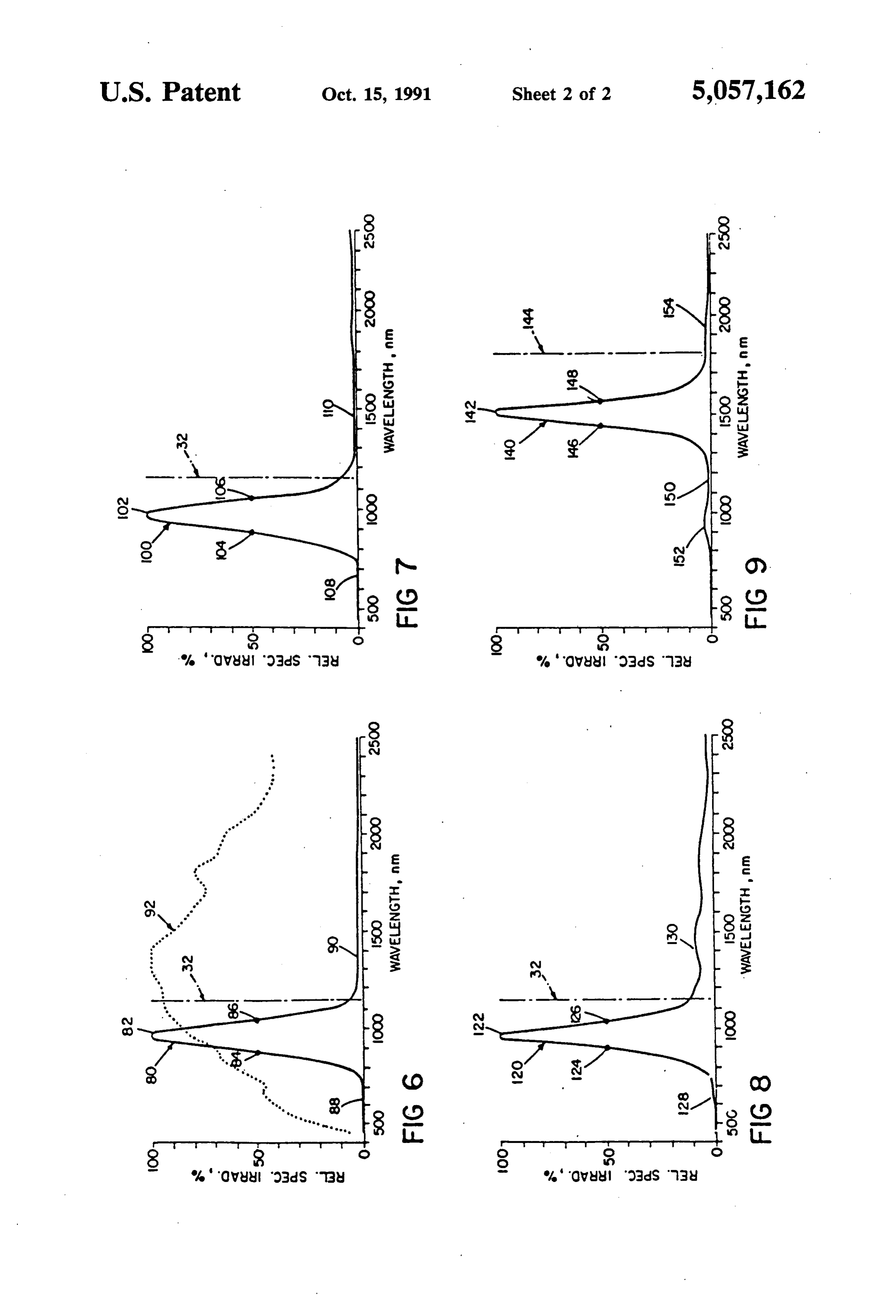
accordance with the invention. Additional efficiency An imbibing solution is formed by dissolving hy enhancement may be obtained by a regenerator through 30 drated ytterbium nitrate (Yb(NO3)34 H2O) (reagent which the hot convection gas is routed to warm the grade) in distilled water (together with a small amount incoming combustion air. of a non-ionic wetting agent such as Triton X-100) to Other features and advantages of the invention will provide a solution 1.75 molar in ytterbium nitrate. be seen as the following description of particular em A knitted rayon sleeve unit, about thirty centimeters bodiments of the invention progresses, in conjunction 35 long, is immersed for about ten minutes in the imbibing with the drawings, in which: solution at room temperature, with gentle agitation to FIG. 1 is an enlarged view of a mantle type radiation promote penetration of the imbibing solution into the source and its support in accordance with aspects of the rayon fibers. After the ten minute imbibition, the sleeve invention; is removed from the solution, squeeze dried and then FIG. 2 is a magnified view of a portion of the rare 40 transferred to a plastic centrifuge tube. The sleeve is earth oxide fabric of the mantle shown in FIG. 1; then centrifuged for ten minutes at about 200g's to re FIG. 3 is a graph indicating spectral characteristics of move surface liquid. It is convenient to secure a metal an ytterbia mantle type radiation source in accordance screen halfway from the bottom of the centrifuge tube with the invention, and of a predominately thoria man so that liquid does not rewet the surface of the sleeve tle type radiation source of similar configuration; 45 during or after centrifugation. FIG. 4 is a diagram of a thermophotovoltaic device in After centrifugation, the imbibed sleeve is formed accordance with aspects of the invention; into mantle socks with aid of a Teflon sock-shaping rod FIG. 5 is a diagrammatic front view of the photocell that is fourteen millimeters in diameter and has a hemi array employed in the thermophotovoltaic device spherical end. A seven centimeter-length of imbibed shown in FIG. 4; SO sleeve is slipped over the shaping rod, and tied off at the FIG. 6 is a graph indicating spectral characteristics of hemispherical and of the shaping rod with a piece of another ytterbia radiation source in accordance with treated yarn unraveled from the bottom of the knit aspects of the invention and spectral characteristics of a sleeve. The shaped sock is then dried with a flow of hot commercially available predominately thoria mantle; (about 90° C) air, slipped off the shaping rod, cut to FIG. 7 is a graph indicating spectral characteristics of 55 about 3.6 centimeters length, and then hung on a fixture another ytterbia radiation source in accordance with that includes a series of upstanding mullite posts (spaced the invention energized with a hydrogen flame; at about three centimeter intervals) on a mullite base. FIG. 8 is a graph indicating spectral characteristics of Each post has a diameter of about three millimeters and an ytterbia-ceria radiation source; and a length of about 3.7 centimeter and receives a support FIG. 9 is a graph indicating spectral characteristics of 60 tube 12 and spacer, the top of tube 12 being spaced an erbia radiation source in accordance with aspects of about five millimeters below the top of the post so that the invention. the top of the shaped sock is supported on the mullite Description of Particular Embodiments post and the lower portion of the shaped sock extends over the support tube 12. Optionally a ring of sodium
The diagrammatic view of FIG. 1 shows a radiation 65 silicate that has been pretreated by heating tube 12 to source 10 of the mantle type that is mounted on support about 900' C. may be carried by tube 12. tube 12 of mullite or other suitable heat resistant mate The fixture with knitted imbibed socks hung over the rial. Support tube 12 has an outer diameter of about five support sleeves 12 on the fixture posts is then subjected
Page 6
to a firing procedure to convert the ytterbium nitrate of about 160 nanometers. The lower skirt 42 of profile imbibed cellulosic mantle socks into densified ytterbia 30 of mantle 10 has measured radiated flux levels of less mantles. than one-half percent of the peak from 400 nanometers In the firing sequence, the fixture with imbibed socks to 725 nanometers, and the upper skirt 44 of profile 30 is placed in a tubular oven that is about 1.2 meters in has radiated flux levels of one percent or less at spectral length and about five centimeters in inner diameter. At wavelengths from 1300 nanometers to 2500 nanometers. ambient temperature (about 25 C.), the oven is flushed In contrast, the Welsbach type thoria mantle of simi with tank nitrogen at a flow rate of 200 cubic centime lar physical size and construction has a broad band ters per minute (a flow velocity of about ten centimeters spectral profile as indicated by curve 34, that profile per minute), and with this inert atmosphere in the oven, 10 indicating a radiated flux at 650 nanometers (in the the oven temperature is increased at a rate of 400 C. per visible region) that is about ten percent of the peak hour The mantle fabric undergoes denitration at about radiated flux; radiated fluxes of about 35% of peak at 160 C. At this point the fabric color changes rapidly 800 nanometers, 51% of peak at 900 nanometers, 62% from white to golden tan. Immediately after this color of peak at 1000 nanometers, 81% of peak at 1100 nano change, oxygen is added to the nitrogen flow at a rate of 15 meters in the near infrared region; a peak radiated flux about five cubic centimeters per minute Heating contin at about 1400 nanometers in the far infrared region (the ues at the same rate to a temperature of about 320 C. spectroradiometer being set to have a slit width of about During this time the color continuously changes from 0.8 mm at that wavelength); and radiated flux intensities golden tan to dark brown or black with modest shrink of about 87% at 1800 nanometers, 64% at 2100 nanome age (about 10%) of the fabric, which indicates partial 20 ters and 50% at 2400 nanometers. It will be seen that the decomposition of the organic material The oven ten ytterbia mantle 10 has a narrow well-defined radiation perature is then held at about 320 C. for about one and peak 36 in contrast with the broad and diffuse radiation one-half hours and the mantle color turns from black to profile 34 of the Welsbach type mantle, as well as al light gray or white. During this soaking interval, the most total suppression of skirts 42, 44 on either side of remaining carbon is oxidized and driven off and the 25 peak 36. The amplitude of peak 36, in absolute terms, is mantle shrinks to about its original dimensions with its substantially greater than (about twice) the peak value lower portion 20 shrunk onto tube 12 essentially as of the broad band radiator (curve 34) (the area under shown in FIG. 1. At the end of the soaking interval, the curve 30 being about one-third the area under curve 34 flow of oxygen is increased to fifty cubic centimeters over the 500-2500 nanometer range). The ytterbia man per minute (a gas mixture of 20% oxygen) and the oven 30 tle 10 thus provides a high output at about one micron, temperature is increased over a twenty-four minute the wavelength of interest.
interval to a temperature of 900 C. The heater is then The thermophotovoltaic system shown in FIG. 4 turned off and the oven is rapidly cooled to ambient incorporates ytterbia mantle 10. Support tube 12 is con temperature. After cooling, each mantle subassembly is nected via a fuel delivery system to fuel reservoir 50 removed from its storage holder post and is exposed to 35 that contains isobutane fuel with outlet tube 52 extend a burning mixture of isobutane and air (at an estimated ing to pressure regulator 54. The high velocity jet at mantle temperature of about 1700' C.) for five minutes flow-through outlet orifice 56 (0.05 millimeter diame to further shrink and densify the ytterbia fabric. ter) is directed through venturi 58 (a throat diameter of The resulting ytterbia fabric, in visual appearance, about one millimeter) to aspirate and mix air with the substantially retains characteristic physical textile attri isobutane fuel for flow through support tube 12 to man butes of its precursor rayon fabric, although it is sub tle 10. Piezoelectric ignitor 60 or other suitable ignition stantially reduced in dimension. This ytterbia fabric has means is utilized to generate a spark after the air/fuel relatively high density, is flexible, and has a minimal mixture delivery system is turned on to ignite the air defect (flaws) microstructure, a concentrated radiated isobutane fuel mixture at the mantle and provide a maxi flux profile and, in the described mantle configuration, 45 mum flame temperature of about 1900 C. . withstands impact loads of two thousand g’s. Mantle 10 is disposed in a polished and passivated The graph of FIG 3 shows a relative spectral irradi aluminum reflector 62 which collects and collimates the ance profile 30 of mantle 10, over a 400-2500 nanometer radiation emitted by mantle 10. A tubular reflector spectral range when that mantle is exposed to an air array 64 directs the radiation from mantle 10 on silicon isobutane. flame (7 sccm isobutane, 113.6 sccm air as 50 photovoltaic cell array 70 that is mounted on heat sink measured with Tylan controllers--an oxidant fuel ratio structure 72. Reflector array 64 is composed of a series of 16.2). Profile 30 was measured over an interval of 3.2 of spaced, overlapping wall sections 66 with ventilation hours with a Beckman DK-2A prism spectroradiometer ports 68. Radiation transmitting thermal isolation win operated in single-beam mode with an adjustable slit dow 74 of glass or other suitable material is supported width. Theoretical photovoltaic response of silicon is 55 on one of the sections 66 and disposed between mantle indicated by curve 32 in FIG. 3; and the relative spec 10 and photocell array 70 for isolating the hot combus tral irradiance profile of a predominantly thoria mantle, tion gas in the mantle compartment from the photovol of similar physical shape to mantle 10 that was ther taic cell array 70. The surfaces of window 74 preferably mally energized with an an air-isobutane flame (7 sccm carry an anti-reflecting coating to lower reflection isobutane, 191.7 sccm air- an oxidant-fuel ratio of 27.4) losses. Preferably, the front surfaces of the photodiodes and measured in the same manner and over the same 76 (FIG. 5) also carry an anti-reflection coating for the wavelength range as profile 30, is indicated by curve 34. same reason that window 74 is coated. To maximize The radiated flux profile 30 of ytterbia mantle 10 has photon conversion, silicon photodiodes 76 preferably a radiation peak 36 at about 985 nanometers (the spec are about one millimeter in thickness. Provision of a troradiometer being set to have a slit width of about 0.6 65 reflecting layer (for example of silver, aluminum or mm at that wavelength) with half intensity points 38, 40 copper) on the back contacts of the photodiodes 76 at about 890 nanometers and 1050 nanometers respec further enhances probability of photon conversion. tively so that peak 36 has a full width at half maximum Control system 78 may be connected between regulator
Page 7
54 and diode array 70 for monitoring the output voltage diameter with its tip about 2.5 centimeters above the and modulating the fuel flow by control of regulator 54 upper end surface of a brass fuel supply support tube to to control the electrical output of the photodiode array which it is secured, the support tube having an outer 70. diameter of about twelve millimeters and an inner diam The optical temperature of ytterbia mantles 10, mea eter of about seven millimeters, the lower portion of the sured with a Leeds & Northrup optical pyrometer (Cat mantle fabric sleeve being firmly shrink-secured to the alog # 8632-C) is in the range of 1160°-1190 C. As the outer surface of the support tube. The mantle fabric is emissivity of the highly reflective mantle material (at composed of ytterbia multi-filament strands in a knit the 660 nm optical pyrometer measuring wavelength) is array that has an open area of about 30%, the cross-sec less than 0.1, the actual temperature of mantle 10 is 10 tional dimensions of the individual ytterbia fibers of the about 1700 C. strands of this mantle being about fifteen micrometers, The electron production threshold of the silicon pho and the strands having cross-sectional dimensions of tovoltaic cells 76 is 150 nanometers, as indicated by about 0.2 millimeter with openings having dimensions curve 32 in FIG. 3. The ytterbia mantle 10, when heated of about 0.3 millimeter.
as described about to about 1700 C., has its peak 36 in 15 This mantle was manufactured from continuous low close proximity to (about 165 nanometers from) silicon twist, low tenacity (highly reticulated), viscose rayon electron production threshold 32 such that the electrical yarn (300 denier/50 filament) that was knitted into a energy conversion efficiency of the system is continuous tubular sleeve using a Lamb circular string high-80% of the total radiated flux output of mantle 10 knitter (Model ST3A/ZA) with a 3.8 centimeter diame over the 400-2500 nanometer wavelength range being 20 ter arbor and sixty needle capacity using sixty equally convertible into electrical energy on the basis of the spaced needles in the arbor with tension on both the theoretical silicon cell response indicated in FIG. 3. yarn and the knitted sleeve to attain eight stitches per The graph of FIG. 6 shows the relative spectral irra linear centimeter of tensioned sleeve. An imbibing solu diance profile 80, over the 400-2500 nanometer spectral tion 1.57 molar in ytterbium nitrate was formed and a range, of a second ytterbia mantle in accordance with 25 length of the knitted rayon sleeve was immersed for the invention. That mantle is formed of a similar tube of about one hour in the imbibing solution at room temper knit rayon that was imbibed in a 1.2 molar ytterbium ature, with gentle agitation to promote penetration of nitrate solution and processed by uniformly torching the imbibing solution into the rayon fibers. After imbibi the dried nitrate impregnated rayon mantle with a blue tion and centrifugation, the imbibed sleeve was formed propane flame to pyrolyze the rayon and shrink the 30 into mantle socks, disposed on brass support tubes, and mantle skirt onto its support tube. That ytterbia mantle processed by uniformly torching the dried nitrate im support tube assembly was energized with an air-isobu pregnated rayon mantle with a blue propane flame to tane flame (air/fuel ratio of 27:1) and its radiated flux pyrolyze the rayon and shrink the mantle skirt onto its was measured over the 400-2500 nanometer spectral brass support tube.
range with the same equipment as described in connec 35 That ytterbia mantle-support tube assembly was then tion with the mantle shown in FIGS. 1 and 2. This exposed to an air-isobutane flame (91 sccm isobutane, ytterbia mantle had a radiation peak 82 at about 970 2460 sccm air as measured with Tylan controllers-an nanometers (the spectroradiometer being set to have a oxidant fuel ratio of about 27:1), and its resulting spec slit width of about 0.6 mm at that wavelength) with half tral irradiance profile was measured with a Beckman peak intensity points 84 and 86 at about 875 and 1060 40 DK-2A prism spectroradiometer operated in single nanometers respectively so that peak 82 has a width at beam mode with the spectroradiometer set to have a slit half maximum intensity of about 185 nanometers. Mea width of about 0.035 mm over the 400-2400 nanometer sured radiated flux levels of lower skirt 88 were less wavelength range. The resulting radiated flux profile of than one-half percent from 450 to 625 nanometers; and that ytterbia mantle had a radiation peak at about 1010 measured radiated flux levels of upper skirt 90 were two 45 nanometers (offset about 140 nanometers below the percent or less at wavelengths from 1300 to 2500 nano silicon threshold) with half intensity points at about 905 meters. Peak 82 is offset about 180 nanometers below nanometers and 1080 nanometers respectively so that its silicon threshold 32. The silicon conversion efficiency peak had a full width at half maximum of about 175 of this ytterbia-isobutane mantle system was 74%. nanometers. The lower skirt of the profile of the mantle Curve 92 is the relative spectral irradiance profile of 50 had measured radiated flux levels of less than one-half a commercial Coleman (Welsbach type) mantle ener percent of the peak, and the upper skirt of the profile gized in an air/propane flame It will be seen that curve had radiated flux levels of seven percent or less at spec 92 has a broad spectral profile similar to curve 34, curve tral wavelengths from 1300 nanometers to 2400 nano 92 having a radiated flux level at 650 nanometers (the meters. The silicon conversion efficiency of this yt upper end of the visible range) of about 46% of its peak 55 terbia-isobutane mantle system was about 72%. The radiated flux; radiated flux levels in the near infrared relative spectral irradiance profile 100 of still another region of about 62% of peak at 800 nanometers, 71% of ytterbia mantle is shown in FIG. 7. The ytterbia fiber peak at 900 nanometers, and 85% of peak at 1000 nano configuration and composition (a 1.74 molar ytterbia meters; a peak radiated flux at about 1400 nanometers imbibing solution was used) were similar to mantle 10. (the spectroradiometer being set to have a slit width of 60 After the ytterbia mantle was carefully burned off in about 0.3 mm at that wavelength); and radiated flux propane, profile 100 was obtained by exposing the man outputs of about 80% of peak at 1800 nanometers, 52% tle to an air-hydrogen flame (maximum flame tempera of peak at 2100 nanometers and 42% of peak at 2400 ture about 2045 C.) with the burner stem orifice re nanometers. The silicon conversion efficiency of this duced to an inner diameter of 0.25 millimeter to avoid Welsbach mantle-propane system is 23%. 65 flashback at the fuel flow rate employed (a 1.52 millime Another mantle in accordance with the invention is a ter burner orifice was used with isobutane fuels) The self-supporting ytterbia fiber fabric structure that de ytterbia mantle was exposed to a air-hydrogen flame (70 fines a hollow chamber of about twelve millimeters in sccm air flow rate, 112 sccm hydrogen flow rate) and
Page 8
measured with the Beckman spectroradiometer oper and half intensity points 146 and 148 were at about 1480 ated in single beam mode with a 0.8 millimeter slit width and 1545 nanometers respectively so that peak 142 had at the 965 nanometer peak. The resulting normalized a full width at half maximum of about 65 nanometers spectral irradiance profile 100 as shown in FIG.7 had a The optical temperature of erbia mantles, measured peak 102 at about 965 nanometers (offset about 185 with a Leeds & Northrup optical pyrometer (Model nanometers from silicon threshold 32), half intensity #8632-C) is in the range of 1400-1450° C. As the emis points 104,106 at about 890 and 1050 nanometers so that sivity of the erbia mantle material (at the 660 nm optical peak 102 had a full width at half maximum of about 160 pyrometer measuring wavelength) is about 0.5, the ac nanometers; a lower skirt 108 that had less than one-half tual temperature of the erbia mantle is about 1600 C. percent measured radiated flux levels from 450 to 675 10 This narrow band erbia radiation source couples well to nanometers and an upper skirt 110 that had radiated flux a germanium photocell and such a thermophotovoltaic levels of about one percent from 1500 to 2300 nanome system has a germanium photocell conversion effi ters (with the exception of a two percent radiated flux ciency of about 77%. The erbia mantle provides a high level at 1900 nanometers). The silicon conversion effi output at about 1.5 microns, the wavelength of interest, ciency of this ytterbia-hydrogen mantle system was 15 in contrast to the lower absolute values of output peaks 76%. The relative spectral irradiance profile of still of comparable broad band radiators of the type indi another mantle system is shown in FIG. 8, a knitted cated by curve 34, for example.
rayon tube of the same configuration as that used for While particular embodiments of the invention have mantle 10 being imbibed with a solution of 1.69 molar been shown and described, various modifications will ytterbia nitrate and 0.035 molar cerium nitrate and then 20 pyrolyzed by burning off in propane. Its radiated flux be apparent to those skilled in the art, and therefore it is not intended that the invention be limited to the dis was then measured with the Beckman spectroradiome ter with the same techniques as employed with the closed tures embodiments or to details thereof, and depar may be made therefrom within the spirit and scope preceding examples employing a slit width of 0.55 milli of the invention.
meter at the 960 nanometer peak. Profile 120 of that 25 What is claimed is:
ytterbia-ceria mantle had a radiation peak 122 at about 960 nanometers (the spectroradiometer being set to tion1. comprisingA method of thermophotovoltaic power genera the steps of have a slit width of about 0.6 mm at that wavelength), providing a rare earth metal oxide radiator member half intensity points 124, 126 at about 900 and 1050 that has a cross-sectional dimension in the range of nanometers respectively so that peak 122 has a full 30 five-thirty micrometers, width at half maximum of about 150 nanometers; a disposing a photovoltaic device in optically coupled lower skirt 128 of less than one-half percent measured relation to said radiation member, said photovol radiated flux levels from 450 to 525 nanometers; about taic device having an electron production thresh one percent of peak radiated flux at 650 nanometers; and old, an upper skirt 130 with radiated flux levels of six to 35 thermally exciting said radiator member to cause it to eight percent from 1300 nanometers to 1900 nanometers emit radiation that has a wavelength peak below and radiated flux levels of three percent or less from said electron production threshold, 2200 nanometers to 2500 nanometers. Mantle profile said radiator member, when heated to about 1700 C., 120 has a silicon conversion efficiency of 58%.
Shown in FIG. 9 is the normalized relative spectral having a concentrated radiated flux over the irradiance profile 140, over a 450-2500 nanometer spec 400-2500 nanometer wavelength range such that at tral range, of an erbia mantle formed by imbibing a least 50% of said radiated flux is within a band less rayon sleeve similar to the sleeve used to form mantle than 400 nanometers in width, 10 with a 0.92 molar solution of erbium nitrate and then directing the emitted radiation from said radiator carefully torching the imbibed sleeve in propane to 45 onto said photovoltaic device to generate an elec pyrolyze the rayon and shrink the mantle skirt on its trical output, said radiator-photovoltaic system support tube. Profile 140 was obtained by exposing that having a photon conversion efficiency of more erbia mantle to a air-isobutane flame (air/fuel ratio of than fifty percent;
26:2). The resulting erbia mantle profile 140 as shown in monitoring the electrical output of said photovoltaic FIG.9 had a radiation peak 142 at about 1500 nanome 50 device with a control circuit; and ters (the spectroradiometer being set to have a slit width modulating the flow of fuel to said radiator in re of about 0.4 mm at that wavelength)-peak 142 being sponse to the monitored electrical output of said offset about 300 nanometers from germanium electron photovoltaic device to control the electrical output production threshold 144; half intensity points 146 and of said photovoltaic device. 148 at about 1430 and 1570 nanometers respectively so 55 2. A method of controlled thermophotovoltaic power that peak 142 had a full width at half maximum of about generation comprising the steps of 140 nanometers; a lower skirt 150 that had less than one providing a radiator of metal oxide material; percent of peak radiated flux for the range of 450-750 disposing said radiator in optically coupled relation to nanometers, and a component 152 at about three per a photocell device, cent of peak intensity from 900 nanometers to 1000 60 igniting a flow of fuel to said radiator to thermally excite said radiator and cause said radiator to emit nanometers; and an upper skirt 154 that had radiated flux levels of two percent or less from 1800 nanometers radiation in a spectral irradiance profile that has a to 2500 nanometers. In a more precise measurement of narrow radiated flux peak, said flux peak having a profile 140 over the 1200-2000 nanometer wavelength full width at half maximum of less than four hun range (the spectroradiometer being set to have a slit 65 dred nanometers and said spectral irradiance pro width of about 0.04 mm)-peak 142 was located at file of said radiator also having suppressed skirt about 1515 nanometers (offset about 285 nanometers characteristics such that, at wavelengths five hun from germanium electron production threshold 144; dred nanometers above and below the flux peak,
Page 9
the radiated flux level of the skirts are less than ten 8. The method of claim 5 and further including the percent of the radiated flux at said peak, steps of supporting said mantle adjacent the outlet port directing the emitted radiation from said radiator of a fuel supply conduit and flowing fuel through said onto said photocell device to generate an amount conduit to said mantle.
of electrical power, said radiator-photocell system 5 9. The method of claim 2 and further including the having a photon conversion efficiency of more step of providing a reflector system for directing the than fifty percent; radiated flux from said radiator to said photocell. monitoring the electrical output of said photocell 10. The method of claim 9 and further including the device with a control circuit; and step of interposing radiation transmitting thermal isola modulating the flow of fuel to said radiator in re- 10 tion means between said radiator and said photocell. sponse to the monitored electrical output of said 11. A method of controlled thermophotovoltaic photocell device to control the electrical output of power generation comprising:
said photocell device. heating a metal oxide radiator with a burner to pro 3. The method of claim 2 wherein said metal oxide duce radiation within a selected wavelength range; radiator material is in the form of structure that has a 15 directing the radiation onto a photovoltaic device to cross-sectional dimension in the range of five-thirty generate an amount of electrical power; micrometers. monitoring the electrical output of said photovoltaic 4. The method of claim 2, wherein said step of ther device with a control circuit; and mally exciting said radiator to heat said radiator to a modulating the fuel flow to said burner in response to temperature in the range of 1500-2000' C. causes said 20 the monitored electrical output of said photovol radiator to emit radiation such that said narrow radiated taic device to control the electrical output of said flux peak is located less than four hundred nanometers the photovoltaic device. below the electron production threshold of said photo 12. The method of claim 11 wherein the radiation has cell. a wavelength within the 400-2500 nanometer range. 5. The method of claim 2 wherein said radiator is a 25 13. The method of claim 11 wherein the radiation has mantle composed of metal oxide strands. a wavelength peak having a full width at half maximum 6. The method of claim 5 wherein said mantle is com of less than 200 nanometers. posed of an oxide of ytterbium; and said photocell is of 14. The method of claim 11 wherein said metal oxide the silicon type. radiator comprises erbium oxide material. 7. The method of claim 5 wherein of said mantle is 30 15. The method of claim 11 wherein said metal oxide composed of an oxide of erbium; and said photocell is of radiator comprises ytterbium oxide material. the germanium type. k k xx
Provenance
- Collection
- Cited prior art
- Original PDF
- patentimages.storage.googleapis.com →
- Filed
- 1990-10-31
- Pages
- 9
- Method
- pdftotext (the PDF's own text layer) + pdftoppm 300dpi page scans
- Source
- Google Patents bibliographic record
- Granted
- 1991-10-15
- Inventors
- Robert E. Nelson; TPV Energy Systems Inc
- Transcribed from
- patentimages.storage.googleapis.com →