patent · US20110005515A1
Solar half parabolic shell smelter with a heliostat on a turntable
13 January 2011
Page 1 — bibliographic record
(19) United States (12) Patent Application Publication (10) Pub. No.: US 2011/0005515 A1
Nix (43) Pub. Date: Jan. 13, 2011 (54) SOLAR HALF PARABOLIC SHELL SMELTER (52) U.S. Cl. ........................................................ 126/686
WITH A HELOSTAT ON ATURNTABLE
(76) Inventor: Martin E. Nix, Seattle, WA (US) (57) ABSTRACT
Developed is a solar cooker with triangle reflective sides.
Correspondence Address: Above and below are two movable solar reflecting panels, that Martin E. Nix can be adjusted to focus light onto an invented frying pan PO Box 95.173 using a glass lid, an insulating pad, and a surrounding plastic Seattle, WA 98145-2173 (US) bag to trap Solar light for cooking. The triangle reflective sides are used also to adjust and Support the two movable Solar (21) Appl. No.: 12/459,719 reflecting panels via movable pegs. In the corners adjacent to the triangle sides, back reflective plate and reflective floor (22) Filed: Jul. 7, 2009 plate is an invented reflective equilateral triangle, to capture O O and reflect light towards the solar frving pan assemblv. At Publication Classification night the t Solar cooker can E. down to Rin a (51) Int. Cl. storage space. The entire Solar cooker is foldable for shipping. F24, 2/6 (2006.01) (123 words).
Page 2
Drawing sheet — no readable text.
Page 3
Drawing sheet — no readable text.
Page 4
Drawing sheet — no readable text.
Page 5
Drawing sheet — no readable text.
Page 6
Drawing sheet — no readable text.
Page 7
US 2011/00055 15 A1 Jan. 13, 2011
SOLAR HALF PARABOLIC SHELL SMELTER place by pegs and holes. The moveable reflective panels are WITH A HELOSTAT ON ATURNTABLE adjusted so as to redirect Sunlight downwards and towards a specific design of cookware, using a frying pan. At the back is
PRIOR ART a reflective plate, and on the floor is another reflective plate, 0001 Solar cooking is not new, but what has been advanc which also directs Sunlight to the Solar cooking area. In the ing is the art of making it more useful and convenient for corner, where the back plate, floor plate and also one of the users. One of the earliest designs were early people using reflective triangular sides meet, is an equilateral triangle. This rocks heated by Sunlight to cook food. equilateral triangle is angled at 60 degrees in all directions, 0002 U.S. Pat. No. 2,859,745 (von Brudersdorff, May 4, and captures sunlight from either of the two moveable reflec 1954) illustrates an early art using a curved surface to focus tive panels, or from the reflective back plate, or from the sun the Sun's energy onto a cooking Surface. directly. The equilateral triangle thus is able to redirect light 0003 U.S. Pat. No. 3,938,497 (Andrassy, Feb. 17, 1976) and concentrate the light towards the cooking dishware. illustrates a tracking Solar cooker with movable reflecting 0017. The frying pan is covered by a clear, perhaps glass, sides, focusing the Sun's energy into a cooking oven, which is lid. Underneath the frying pan is an insulating pad, so as to designed-to be constantly level. insulate the bottom. Surrounding the entire assembly is a 0004 U.S. Pat. No. 4,077,391 (Way, Mar. 7, 1978) illus clear plastic bag, designed to trap Solar heat. This plastic bag trates a portable Solar cooker using a plurality of adjustable can be made of high temperature resistant plastic, and works Sun reflectors, focusing the Sun's energy below a transparent much like a greenhouse.
window. 0018. At night when the invented device is not used, the 0005 U.S. Patent Apr. 4, 1978 (Rodgers, Apr. 4, 1978) upper and lower reflective panels can be lowered to create an illustrates: an oven and grill with reflecting panels above, interior cavity thus storing the frying pan and other accesso below, on the sides and in the corners, focusing the Sun's ries. A peg and hole assembly locks the lowered reflective energy into a cooking chamber. panels.
0006 U.S. Pat. No. 4,130,106 (Clevett, Dec. 19, 1978) 0019. The invented device is pointed at the sun at least illustrates a solar stove having four rectangular reflective hourly, during Sunny conditions. The invented device is more panels, with adjacent triangular reflectors. The interior of the ergonomic in that it has a small “footprint, and thus uses less drawer is dark to absorb solar energy. floor or table space when in use. It is easy to use, and under 0007 U.S. Pat. No. 4,196,721 (Posmansky, Apr. 8, 1980) stand. Temperatures have been measured at 300 F. degrees, illustrates the use of a vacuum for trapping solar heat into a capturing close to 1,000 BTUs per hour, in test. The invented flask to heat a liquid. device is also foldable for easy shipping. 0020. The invented solar cooker is an improvement in the 0008 U.S. Pat. No. 4,236,508 (Kerr, Dec. 2, 1980) illus culinary art of Solar cooking. It can be made out of plastic, trates a kit to teach principals involving insulation, reflection, metal, wood, cardboard or other suitable materials. The Solar ray conversion to Solar heat, and the fine art of Solar reflective surface can be aluminum mylar (potato chip bags) cookery. or silver mylar, or electroplated with aluminum oxide, gold, 0009 U.S. Pat. No. 4,619,244 (Marks, Oct. 28, 1986) silver, or other reflective materials. The dishware can be com illustrates a Solar heater using phase-change materials, thus monly found, even at thrift stores, thus making the invented illustrating the use of thermal mass for Solar heat storage. device affordable and easy to make. The invented device also 0010 U.S. Pat. No. 4,655,196 (Kerr, Apr. 7, 1987) illus can be used for other applications like distillation of water or trates a Solar cooker that can be installed in a wall of a home alcohols, drying of fruit or fish, disinfecting medical instru or building. ments, or sterilization.
trates a solar oven with a collapsible reflector assembly with FIGURES an interior cooking chamber.
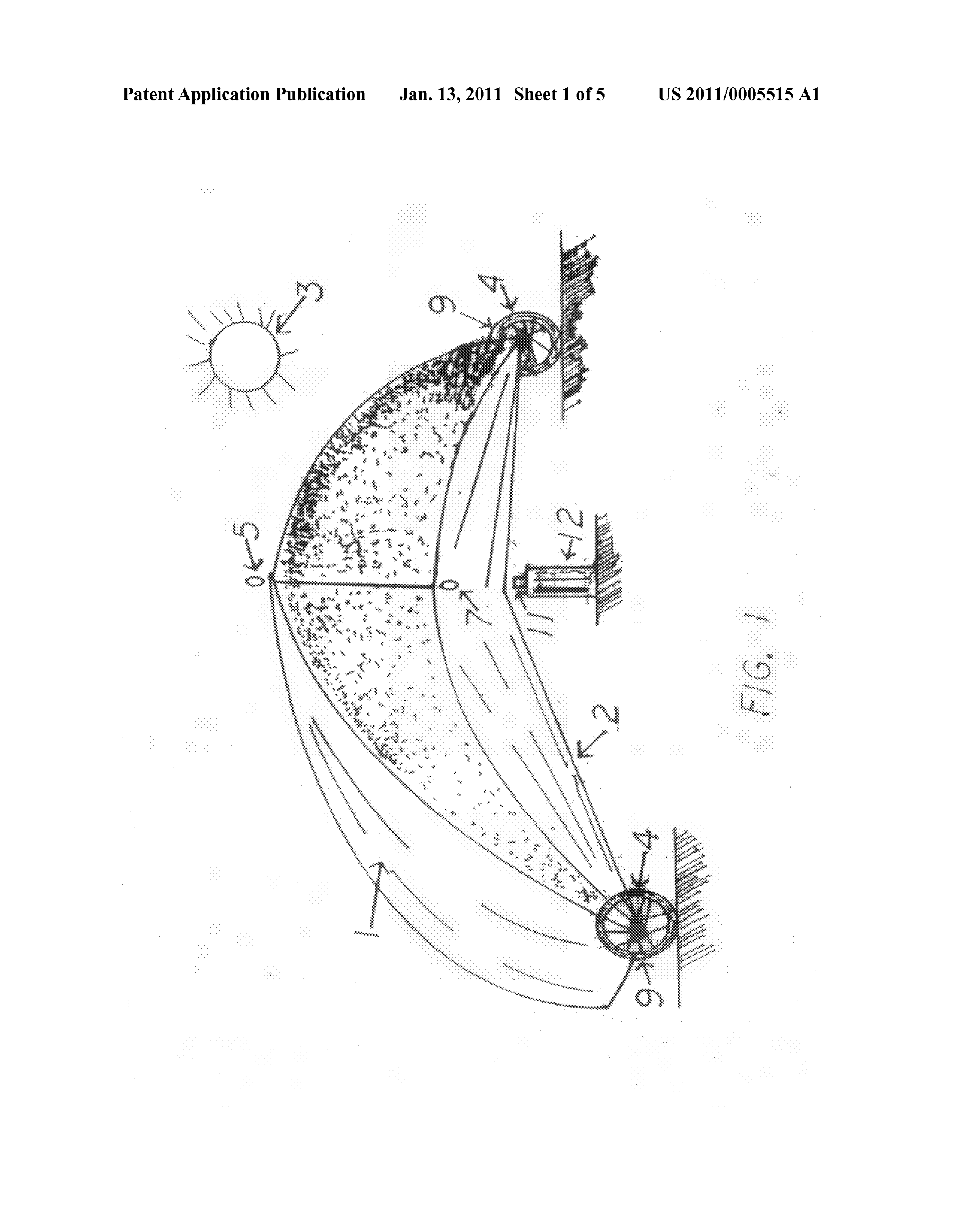
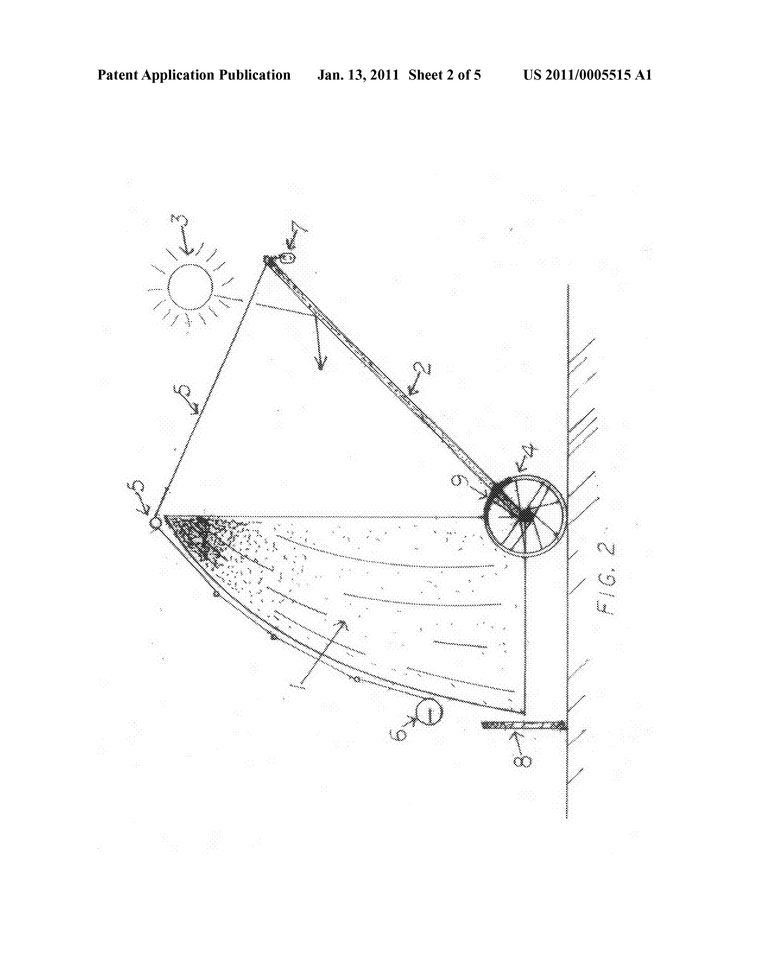
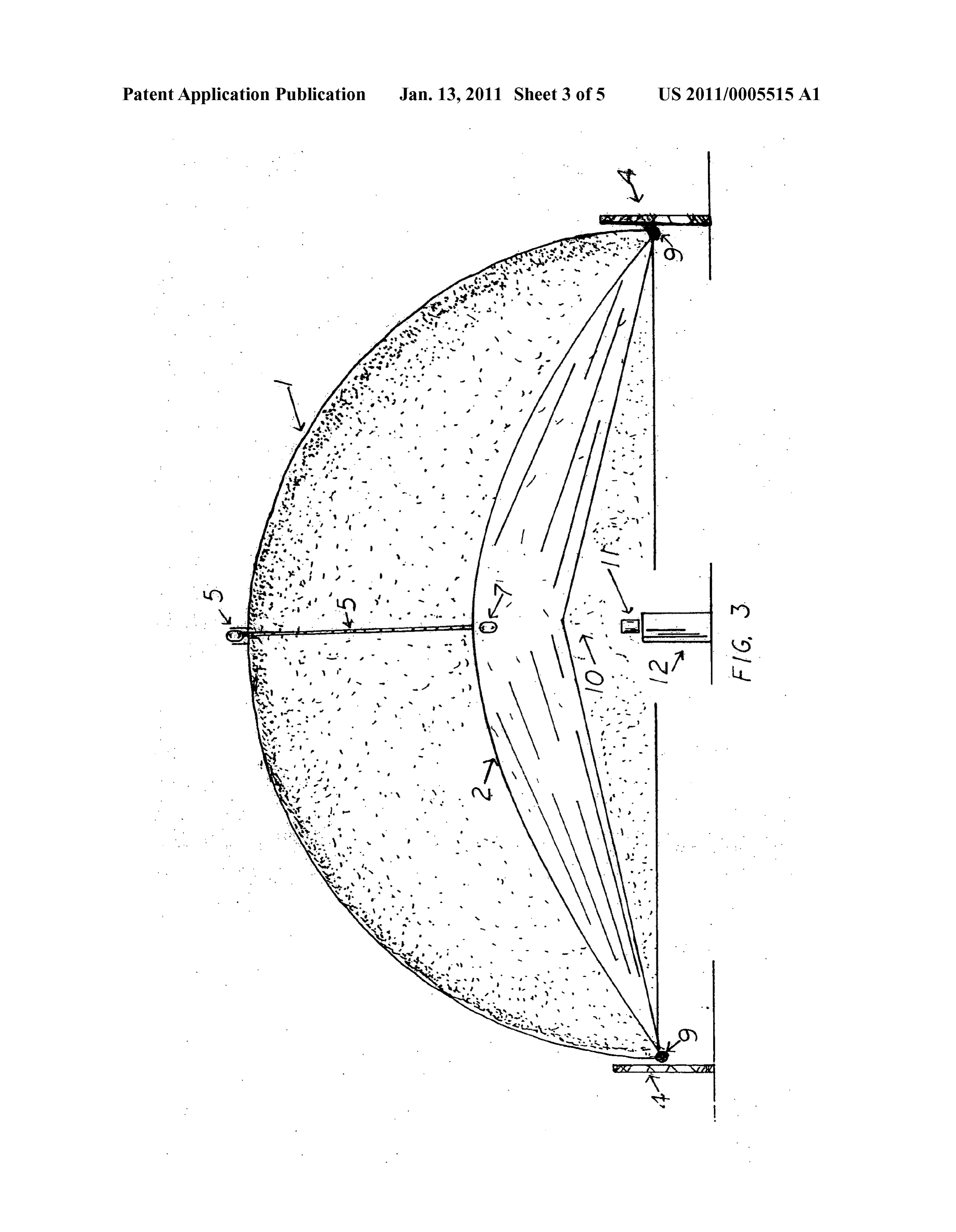
0012 U.S. Pat. No. 4,850,339 (Ghatak, Jul. 25, 1989) 0021 FIG. 1 illustrates a isometric view of the invented illustrates a Solar oven with a rectangular cooking pan. device. Shown are two movable reflective panels, held in 0013 U.S. Pat. No. 5,113,845 (Nix, May 19, 1992) illus place by moveable pegs. On the side are two triangular reflec trates the use of a reflecting adjustable table top, to reflect tive plates that also have holes for holding in place the pegs. light downward onto a parabolic Surface. Unique is a Solar A cutaway is shown for the Solar frying pan. oven with dual glass chambers with an overhead solar absorb 0022 FIG. 2 illustrates a side view of the invented device. ing cast iron plate. The entire oven is surrounded by a high Shown are two movable reflective panels, held in place by temperature plastic bag. moveable pegs. On the side is shown one of the two triangular 0014 U.S. Pat. No. D484,736 (Surmoff, Jan. 6, 2004) reflective plates. Also shown are the holes for holding the shows the design of a foil tent that can be used as a roaster. pegs. A cutaway is shown for the Solar frying pan. 00.15 All of the above art illustrate that solar cooking 0023 FIG.3 illustrates frontal view of the invented device. technology has grown considerably, integrating the basic Shown are two movable reflective panels, held in place by principles of heat transfer. The invented device improves moveable pegs. Also shown are the reflective back plate, and upon the technology. reflective floor plate.
0024 FIG. 4 illustrates the equalateral reflective triangle.
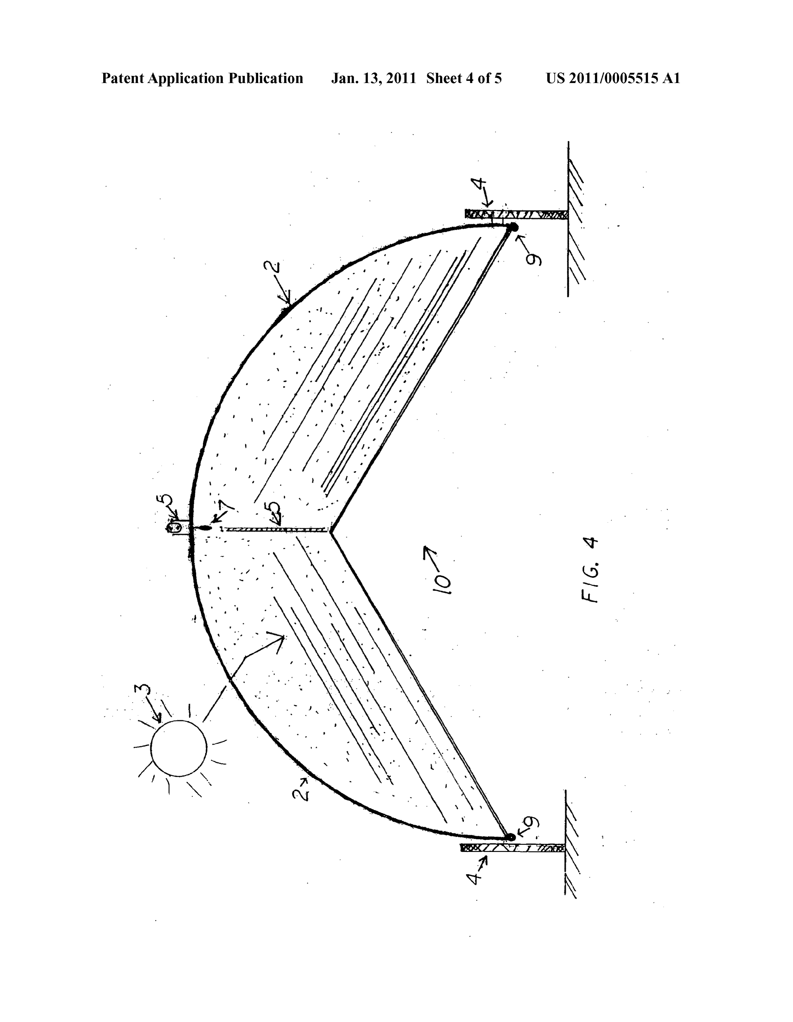
SUMMARY OF INVENTION This triangle is placed in the corner adjacent to one of the reflective triangular reflective plates, and adjacent to the 0016 Described is an improvement in the art of solar reflective floorplate and reflective back plate. The net result is cooking, cooking food with Sunlight. Described is a triangle to capture direct Sunlight, Sunlight from the reflective trian shape Solar cooker, with two reflective triangular sides. gular reflective plates, and reflective floor and back plates and Above and below are two moveable reflective panels, held in from the upper and lower moveable reflective panels, and
Page 8
US 2011/00055 15 A1 Jan. 13, 2011
redirect Sunlight to focus on the Solar frying pan. The net able reflective panel (2) to hold the panel (2) in place, even in result is numerous Suns are focused onto the cooking Surface. wind. Shown also is the reflective back plate (5), and the 0025 FIG. 5 shows the invented cooking dishware. Illus reflective floor plate (12). Shown also is the left triangular trated is a metal frying pan, which absorbs and captures reflective plate (11) and the right triangular reflective plate Sunlight, thus storing the heat of the Sun's energy in the (13). All of which focus the Sun's rays downward towards a thermal mass. On top is a clear glass lid that transmits the cooking area.
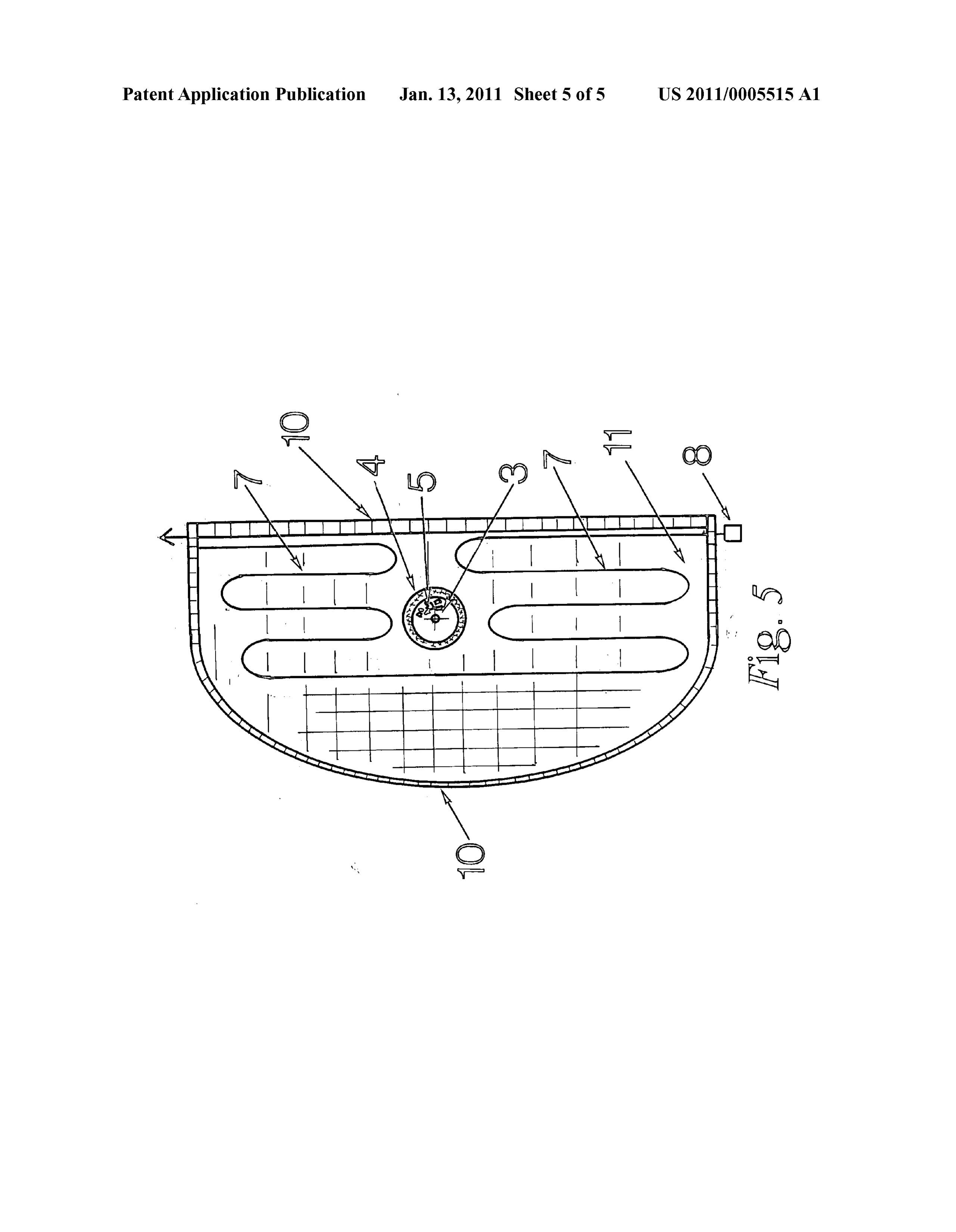
Sun's light into the frying pan cooking chamber. On the bot 0029 FIG. 4 illustrates the reflective equilateral triangular tom is an insulating pad that insulates and traps the Sun's heat, plate (6). This is positioned in the dual corners of the invented and protects the solar cooker floor from excessive heat. Sur device. The equilateral triangular plate (6) is adjacent to the rounding the entire assembly is a high temperature plastic reflective floor plate (12), and also adjacent to the rear back bag, to capture and store the Sun's thermal energy, much like plate (5). There are two of these (6). This reflective equilateral a greenhouse. triangular plate (6) is adjacent also to the right reflective triangular side (13), and in the opposite hand is adjacent to the
DETAILED DESCRIPTION left triangular reflective side (11). The equilateral triangular plate is used to capture light from all reflective surfaces and 0026 FIG. 1 gives a perspective of the invented device. redirect it towards the cooking area. The net result is a con Shown is the Sun (1), which directs solar energy (1) towards centration of Solar energy.
the entire invented device. Sunlight bounces off the upper 0030 FIG. 5 illustrates the cooking dishware (10). The reflective panel (3). This upper reflective panel (3) is move frying pan (14) may be made of metal, like cast iron. This able up and down, hinged off the reflective back plate surface stores and captures the heat of Solar energy, and with the (5). On the sides are reflective triangular plates (11,13), with thermal mass keeps hot, even if a cloud is overhead. Under one on the right side (13) and the other on the left side (11). neath the frying pan (14) is an insulating pad (16), which traps The reflective interior captures any stray Sunlight and redi the heat of the frying pan (14), but also prevents heat from rects it downward towards the solar cooking area (10). Below being conducted to the invented device. Overhead of the is another reflective and moveable panel (2). This panel (2) is frying pan (14) is a clear or glass lid (15). This allows light to hinged off the lower reflective floor plate (12). The second be transmitted to the frying pan (14). Surrounding the entire panel (2) redirects sunlight (1) to the cooking dishware (10). assembly (10, 14, 15, 16) is a clear plastic bag (17) that is Illustrated also are holes (4) for pegs (18). This hole and peg designed not to melt in heat. The clear plastic bag (17) cap (4, 18) assembly is used to hold the reflective plates (2.3) in tures solar heat, like agreenhouse, keeping the entire cooking place, and unmovable even in the wind. This allows for the area hot (10). The low center of gravity, caused by the frying user to adjust the panels (2.3) to the desired angle to reflect pan (10) being located at the bottom holds the entire invented light (1) onto the cooking dishware (10). Also, illustrated are device stable even in wind.
two holes (9), which can be used to lock the moveable plates 0031. A tie (7) seals the plastic bag (17). (2.3) into lowered position using a peg. This creates a storage I claim:
space for after-use for the dishware, and other accessories. 1. A solar-cooker, said solar-cooker with dual reflective 0027 FIG.2 shows a side elevation of the invented device. equilateral-triangles, said equilateral-triangles tilted at a 60 The Sun's energy (1) bounces off two moveable reflective degree angle in all three dimensions the equilateral-triangle panels (2.3), as shown by straight arrows. The movement of side adjacent and attached to a horizontal-reflective-floor the moveable reflective panels (2.3) is shown by curved plate, another equilateral-triangle side adjacent and attached arrows. The light bounces into the invented device onto the to a vertical-reflective-back-plate, and another equilateral back reflective plate (5) or onto the reflective floor (12). Holes triangle side adjacent and attached to a triangle-shaped-re (4) are shown for the pegs. These holes (4) are used to adjust flective-side, said triangle-shaped-reflective-side located ver the location and angle of the moveable reflective panels (2.3). tically and attached either on the left side or right side of said Shown also is a hole (9) for locking the reflective panels (2.3) horizontal-reflective-floor-plate, the triangle-shaped-reflec into a lowered position, thus creating a storage space for the tive-side located vertically and attached either on the left side solar cooking dishware (10). As shown by the dotted line (8), or right side of the vertical-reflective-back-plate, the triangle the two reflective panels (2.3) are lowered thus trapping any shaped-reflective-side containing holes for a moveable-re thing desired to be stored in the created cavity. Shown also is flective-lower-panel and holes for a moveable-reflective-up the equilateral reflective triangle (6). This equilateral reflec per-panel, said holes used for pegs to hold said moveable tive triangle captures light from the Sun (1), the upper and reflective-lower-panel and said moveable-reflective-upper lower moveable reflective panels (2.3), and from the reflective panel at the desired reflection angle, the moveable-upper back plate (5) and reflective floorplate (12), and also any stray reflective-panel hinged to the said vertical-reflective-back light from the reflective triangular sides (11, 13). The equi plate, the moveable-lower-reflective-panel hinged to said lateral reflective triangle (6) then redirects the light towards horizontal-reflective-floor-plate, means to redirect and con the cooking dishware (10). centrate Sunlight towards a cooking area. 0028 FIG. 3 illustrates a frontal view of the invented 2. A Solar cooker, using a fry pan, said fry pan made of device. Overhead is a moveable reflective panel (3), held in metal or cast iron, the fry pan covered by a clear or glass lid, place by a peg (18). The peg (18) can be in front and also the fry pan with an insulating pad underneath, with the entire behind the moveable reflective panel (3), thus trapping it, and assembly Surrounded by a high temperature plastic bag, keeping it unmovable, even in wind. Also shown is a lower means to capture Solar energy and heat and cook food. moveable reflective panel (2), held in place by a peg (18). c c c c c There can be also another peg (18) on top of the lower move
Provenance
- Collection
- Patents citing this work
- Pages
- 8
- Method
- pdftotext (the PDF's own text layer) + pdftoppm 300dpi page scans
- Patent office record
- patents.google.com →
- Source
- Google Patents citing-documents table
- Assignee
- Nix Martin E
- Inventors
- Martin E. Nix
- Published
- 2011-01-13
- Transcribed from
- patentimages.storage.googleapis.com →