patent · US5529054
Solar energy concentrator and collector system and associated method
25 June 1996
Page 1 — bibliographic record
United States Patent (19 11 Patent Number: 5,529,054 Shoen (45) Date of Patent: Jun. 25, 1996 54). SOLAR ENERGY CONCENTRATOR AND 4,788,555 11/1988 Schultz et al. ... ... 126/438 X COLLECTOR SYSTEMAND ASSOCIATED 4,865,266 9/1989 George ...................................... 244/31 METHOD 5,347,986 9/1994 Cordy ... ... 26/574 5,404,868 4/1995 Sankrithi ................................. 126/604 76 Inventor: N. She 25 state Pl, Primary Examiner-Larry Jones all nersburg, Md. Attorney, Agent, or Firm-R. Neil Sudol; Henry D. Coleman 21 Appl. No. 262,554 57 ABSTRACT (22 Filed: Jun. 20, 1994 A power generating system comprises a solar concentrator 6 defining an effectively concave reflective surface on a sur (51) Int. Cl. ......................................................... F24J 2/08 face of the earth for concentrating incoming solar energy. A 52 U.S. Cl. .......................... 126/681; 126/680; 126/685; solar collector is disposed in an underground chamber 126/600; 126/714 provided with an access opening. The solar collector (58) Field of Search ..................................... 126/600, 685, receives solar energy concentrated by the concentrator and 126/680, 681, 714 converting the concentrated solar energy to another energy 56 References Cited form, generally thermal energy, which is subsequently con vertible to electrical power. Directional componentry is
concentrator along a predefined folded transmission path 683,089 9/1901 Wideen ................................... 126/681 through the access opening to the collector. 4,070,861 1/1978 Scragget al. 126/681 X 4,364,532 12/1982 Stark ......................................... 244/30 4,581.897 4/1986 Sankrithi............................. 126/680 X 37 Claims, 3 Drawing Sheets
ROTARY AND
TRANSLATORY
DRIVE
TRANSLATORY
AND ROTARY
DRIVE
NNNNN
-1 UNIT
Page 2
Drawing sheet — no readable text.
Page 3
Drawing sheet — no readable text.
Page 4
Drawing sheet — no readable text.
Page 5
SOLAR ENERGY CONCENTRATOR AND the earth for concentrating incoming solar energy. A solar COLLECTOR SYSTEMAND ASSOCATED collector is also disposed on the earth's surface. The solar METHOD collector receives solar energy concentrated by the concen trator and converts the concentrated solar energy to another
BACKGROUND OF THE INVENTION 5 energy form, generally thermal energy, which is subse quently convertible to electrical power. Directional compo
This invention relates to a power generating system and nentry is provided for directing concentrated solar energy an associated method. More particularly, this invention from the concentrator along a predefined folded transmis relates to a solar energy power station and an associated sion path to the collector.
method for generating energy from incoming solar radiation. 10 According to a preferred feature of the present invention, Solar energy collection facilities have not come into the collector is disposed in an underground chamber or general use mainly owing to cost. Although solar energy is cavity for purposes of collecting energy which is reradiated clean and environmentally safe and basically limitless, the by the collector.
costs of building and operating solar energy facilities, as According to another feature of the present invention, the well as relatively low operating efficiencies, have kept the 15 directional componentry includes a pair of mirrors spaced price of solar power well above the costs of conventionally from one another, as well as shifting elements operatively generated electrical power. connected to the mirrors for moving the mirrors to track the Large solar energy collection facilities which rely on a sun, i.e., to ensure continued guidance of the concentrated high-temperature thermal energy intermediate for the con solar energy through the access opening to the collector version from solar energy to electrical power conventionally 20 during a substantial portion of a day. The shifting elements comprise a primary reflector having a multiplicity of mov may include one or more rotary drives operatively connected able reflective segments. The reflective segments direct to one of the mirrors for pivoting that mirror. Where one incoming solar radiation to an elevated thermal generator mirror is located at a greater elevation than the concentrator subassembly. This thermal generator subassembly is and the other mirror, the shifting elements may further mounted on an expensive tower and is exposed or accessible 25 include a translatory drive operatively connected to the from generally all directions to receive radiation reflected higher mirror for shifting that mirror laterally. The second, from each segment of the primary reflector. The movable lower mirroris preferably located in relative juxtaposition to reflector segments each require a motor and control unit to the access opening to the underground chamber and is track the sun, which contributes to expense and reduces pivoted by the rotary drive to guide, through the access reliability especially in harsh environments such as wind 30 opening, radiation concentrated by the concave reflective blown sandy deserts. surface and reflected downwardly by the first mirror. One source of inefficiency in this conventional system is In a solar power system in accordance with the present re-radiation of energy from the thermal collector/generator invention, the concentration of solar radiation is accom surfaces. Energy concentrated from incoming solar radiation plished by a stationary reflector, while the tracking of the sun is is thus lost to the environment rather than being converted 35 is implemented by two relatively small mirrors. In contrast into electrical power. with conventional solar collecting assemblies of the thermal Another disadvantage of this conventional solar energy conversion type, which have multiple concentrator segments collection facility is thermal time constant problems result each moved by its own driving or tracking device, a solar ing in lost operation due to a slow ramp-up to operating 40 power system in accordance with the present invention temperatures during solar "downtime” (night time). Another requires drives for just two mirrors.
factor affecting the economic viability of this system is the The primary reflector may itself comprise a multiplicity of need for off-cycle auxiliary power (some systems use natural mirror segments, to facilitate assembly or installation. How gas). ever, all of these mirror segments are fixed to the earth and
require no moving parts. This reduction in the number of moving parts not only reduces initial capitalization expen
An object of the present invention is to provide an moving ditures but also reduces maintenance costs since it is the improved solar collecting system. parts which are most likely to require replacement Another object of the present invention is to provide a or repair. Damage to the primary reflector by the elements solar collecting system of the thermal conversion type 50 ground can be further reduced by disposing the reflector below wherein power costs are reduced as compared with conven level, in a depression or recess. tional thermal conversion type solar collecting assemblies. The directional mirrors may be configured to further focus Another, more particular, object of the present invention the concentrated solar rays from the primary reflector. is to provide such a system which has higher thermal According to a further feature of the present invention, the conversion efficiencies and less expensive housing and 55 directional componentry includes a lighter-than-air balloon Support structures. supporting the first or higher mirror. The balloon with its A further object of the present invention is to provide an attached mirror is anchored to the surface of the earth by a associated method for converting solar energy into electrical plurality of tension cables. In that case, the shifting of the power. mirror may be accomplished by selectively paying out and 60 alternately retracting the cables.
These and other objects of the present invention will be Of course, the concentration of solar radiation may be apparent from the drawings and detailed descriptions herein. implemented by a plurality of concave reflective surfaces SUMMARY OF THE INVENTION spaced from one another on the surface of the earth. In that event, the directional componentry includes a plurality of
A power generating system comprises, in accordance with 65 mirrors equal in number to the reflective surfaces and each the present invention, a solar concentrator defining an effec disposed at a greater elevation than a respective reflective tively concave stationary reflective surface on a surface of surface. Where the directional componentry includes shift
Page 6
ing elements operatively connected to the mirrors for mov form other than heat, heat energy absorbed upon radiation ing the mirrors to ensure continued guidance of the concen from the collector. Thus, the heat in the moving fluid may be trated solar energy through the access opening to the used to power steam turbines to generate electrical energy. collector during a substantial portion of a day. Alternatively, the fluid may be conveying to the primary It is generally contemplated that the collector includes a collector (e.g., boiler) for contributing to the heat collection boiler. The boiler may be operatively coupled to steam thereby.
turbines for driving electrical generators. Pursuant to a supplemental feature of the present inven According to an additional feature of the present inven tion, where the step of reflecting includes the step of tion, the underground chamber is provided with a heat absorbing lining, whereby energy radiating from the collec 10 reflecting surface of the solar energy from a reflective surface on the the earth, the method further comprises the step tor is at least partially captured. of initially reflecting the solar energy from an auxiliary According to a supplemental feature of the present inven reflector in geostationary orbit above the earth, prior to tion, an auxiliary reflector is disposed in geostationary orbit reflecting the solar energy from the reflective surface. The above the earth and positioning elements are fixed to the auxiliary reflector may be aimed, as discussed above, auxiliary reflector for aiming the auxiliary reflector towards 15 towards the reflective surface during a substantial portion of the reflective surface on the earth during a substantial night time at the reflective surface by operating a plurality of portion of night time at the collector. In this way, the solar thrusters on the auxiliary reflector in response to alignment energy collection facility can be used through as much as 80 signals carried by laser from the surface of the earth. percent of the normal night time, in addition to the day light hours. This will increase efficiency and concomitantly 20 Pursuant to yet another feature of the present invention, reduce energy costs. where the step of reflecting includes the step of reflecting the The auxiliary reflector may be positioned to continuously solar energy from a reflective surface on the surface of the reflect solar rays to the ground based primary reflector or earth, the method further comprises the steps of (i) reflect reflective surface by a plurality of ion thrusters. These outer ing, from the reflective surface, radio waves originating in thrusters may be powered by solar energy collected by solar 25 radio space, (ii) receiving the reflected radio waves via a cells attached to the auxiliary reflector. The thrusters may be antenna disposed above the reflective surface, and (iii) controlled in response to an alignment signal carried from transmitting the radio signals from the antenna for storage the primary reflector or reflective surface via a lower-power and for subsequent radio signal processing. Generally, it is laser beam generated at the earth's surface proximately to contemplated that these steps of reflecting, receiving and the primary reflector. 30 transmitting are performed during night time at the reflective surface. However, daytime use is also possible.
Alternatively, the costs of the solar power facility can be In a solar energy collection system in accordance with the spread out by utilizing the earth bound hardware for other present invention, the folded optical path generated by the purposes. For example, if a radio antenna is disposed above directional mirrors allows the placement of the Solar energy the primary reflector or reflective surface and is connected for radio signal processing, then radio astronomers may use below ground thermal 35 collector (e.g., level, converter unit or boiler) at ground or thereby resulting in higher thermal the facility at least during the night hours. conversion efficiencies and less expensive housing and A power generating method comprises, in accordance support structures.
with the present invention, the steps of (a) reflecting solar The stationary primary reflector permits use of the facility energy at least partially upwardly from a surface of the earth, 40 during off-cycle hours (e.g., at night) as a radio astronomy (b) directing the reflected energy along a folded path to a facility which enables cost sharing in both construction and solar energy collector in an underground chamber, (c) focus operation of the facility.
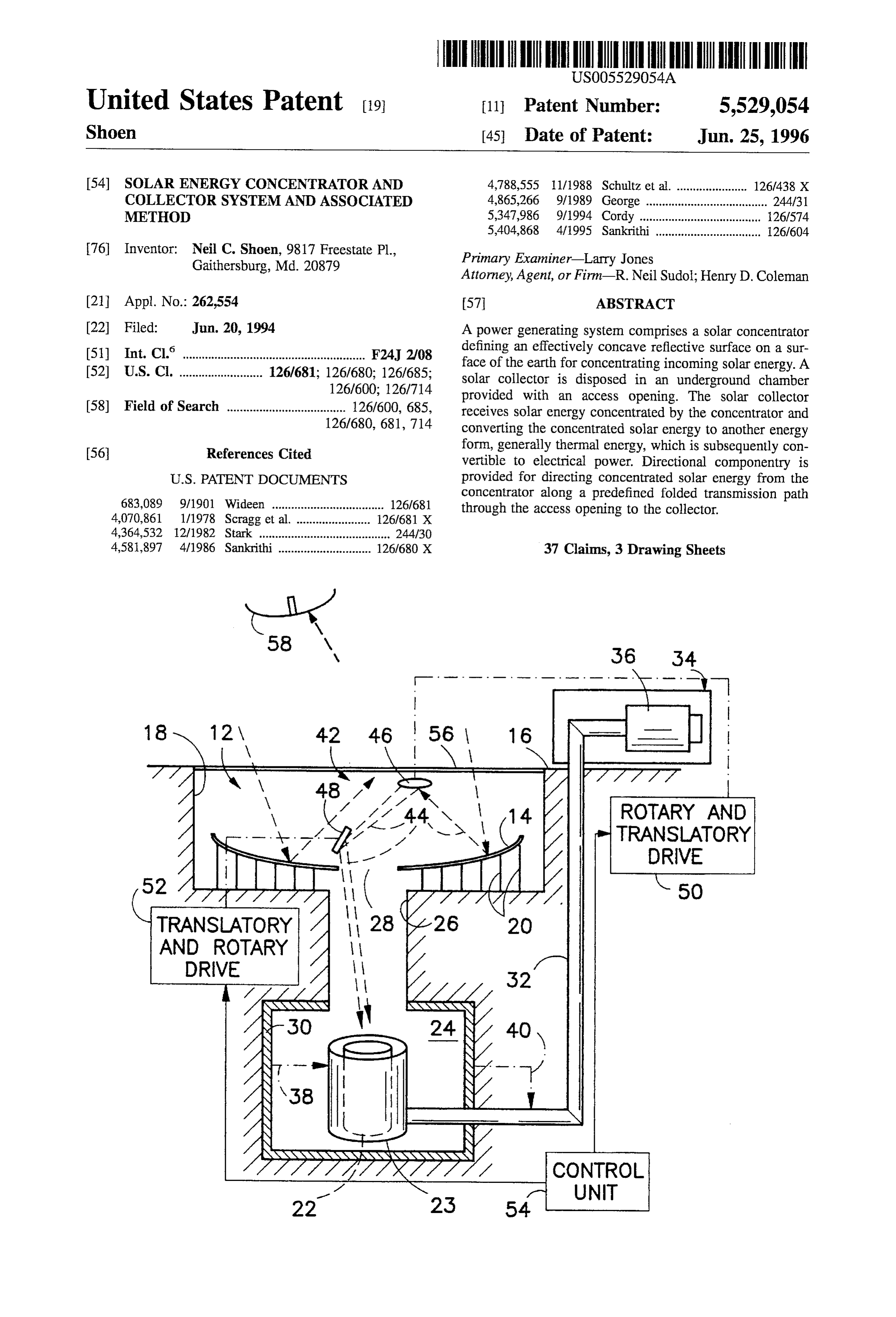
ing the reflected energy upon the collector, and (d) operating the collector to convert the concentrated solar energy to another energy form. BRIEF DESCRIPTION OF THE DRAWING
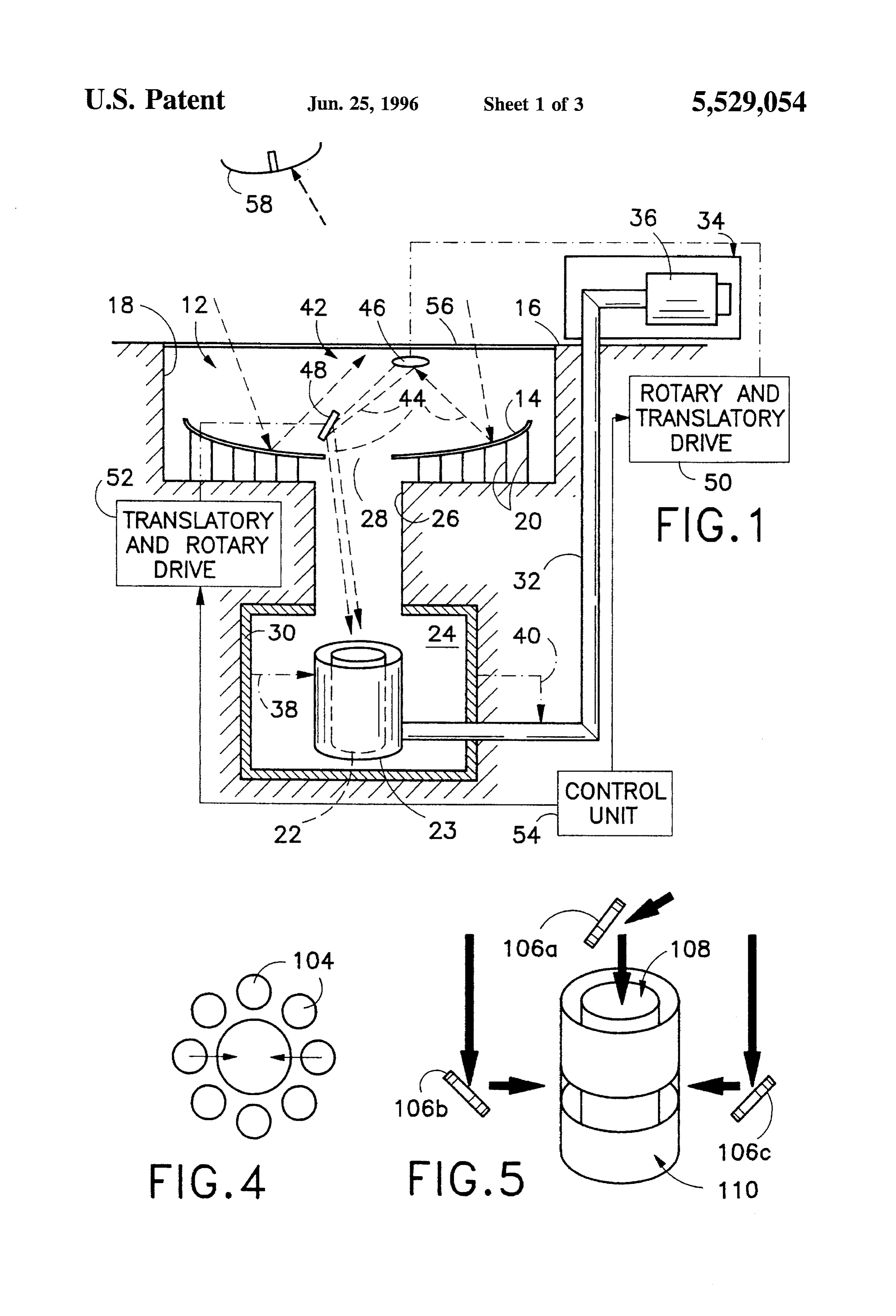
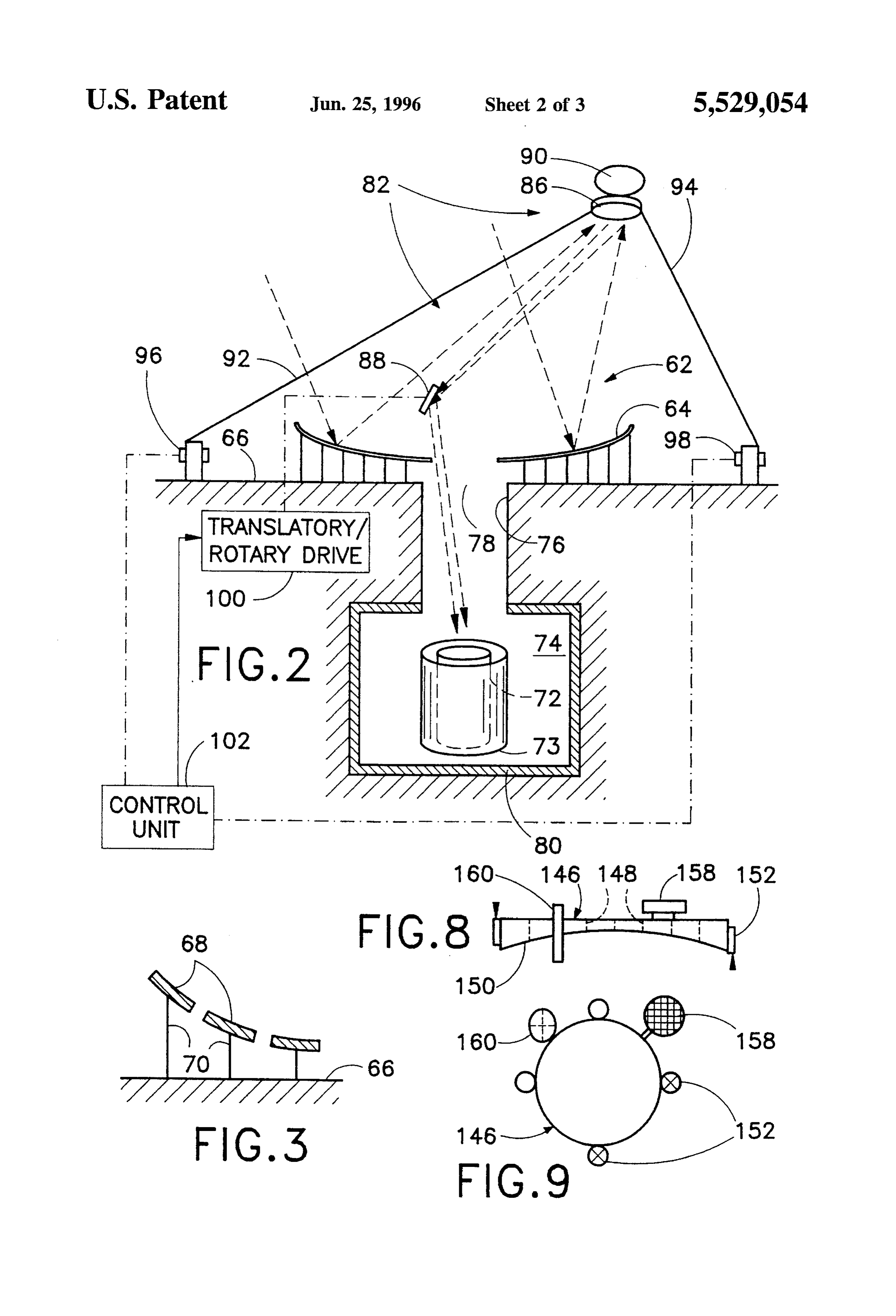
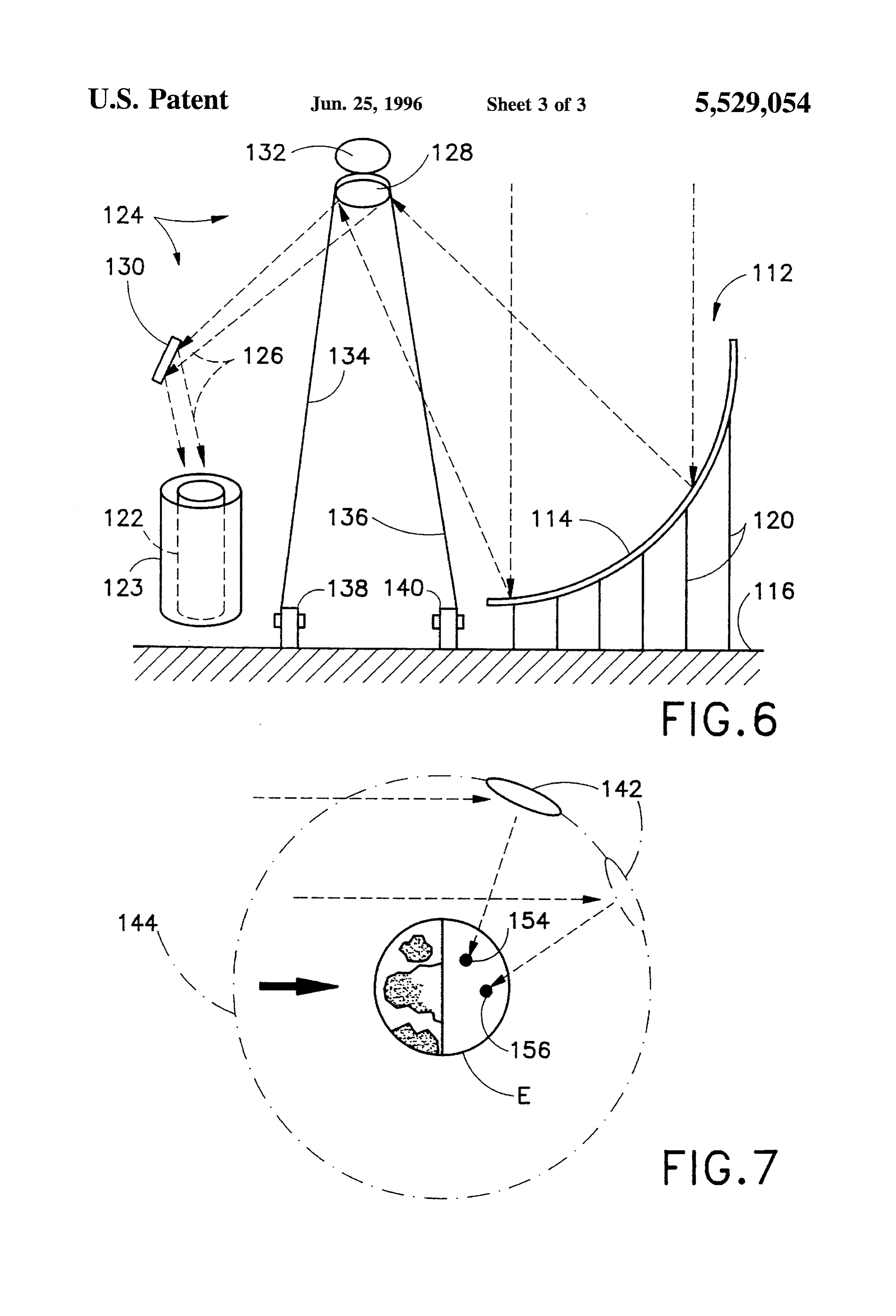
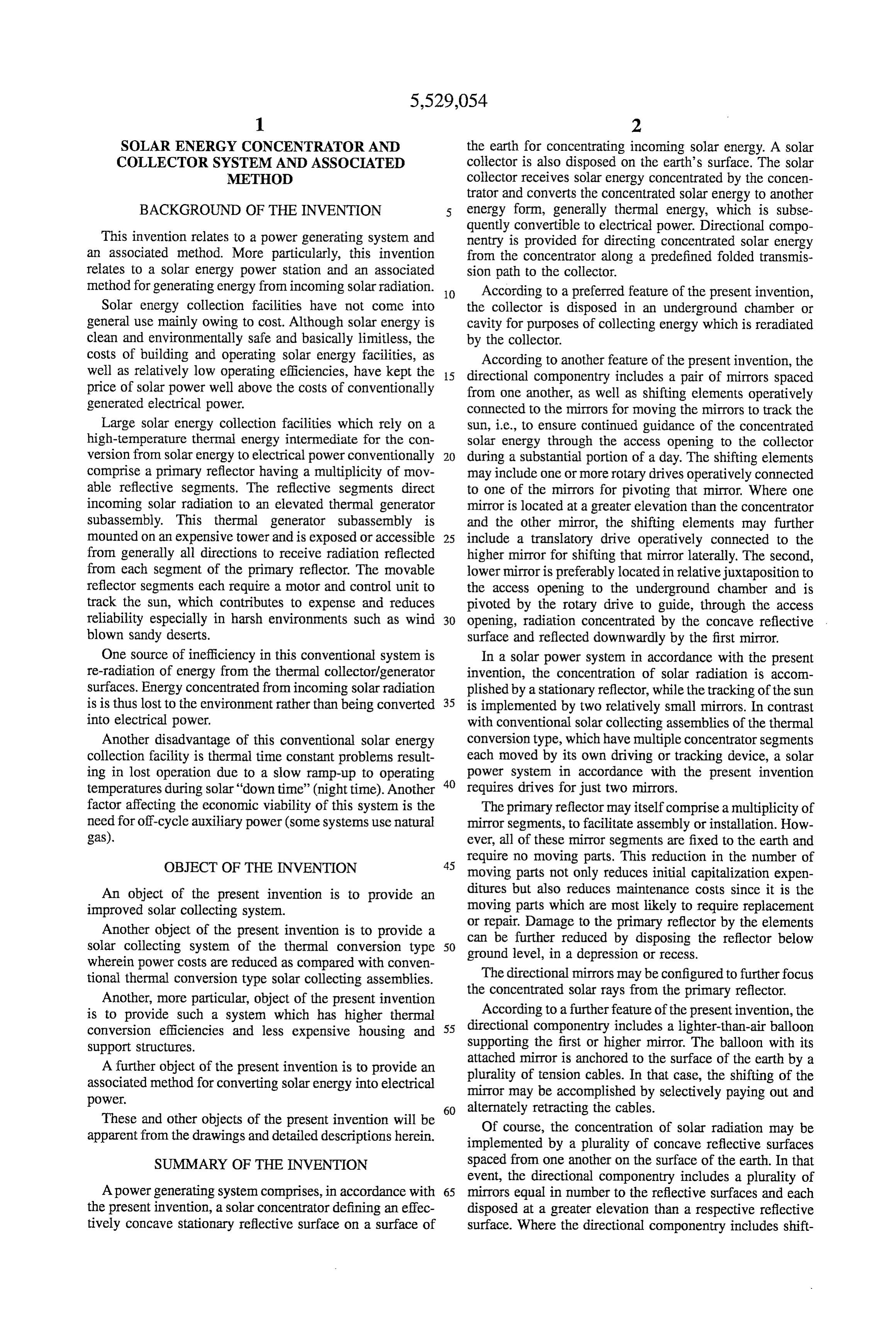
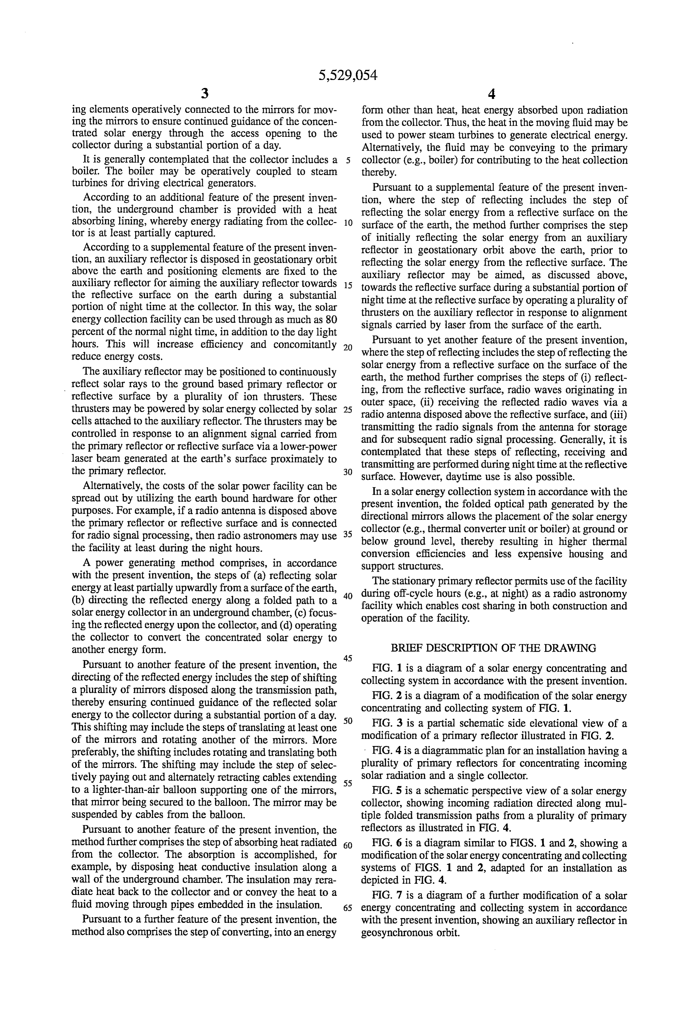
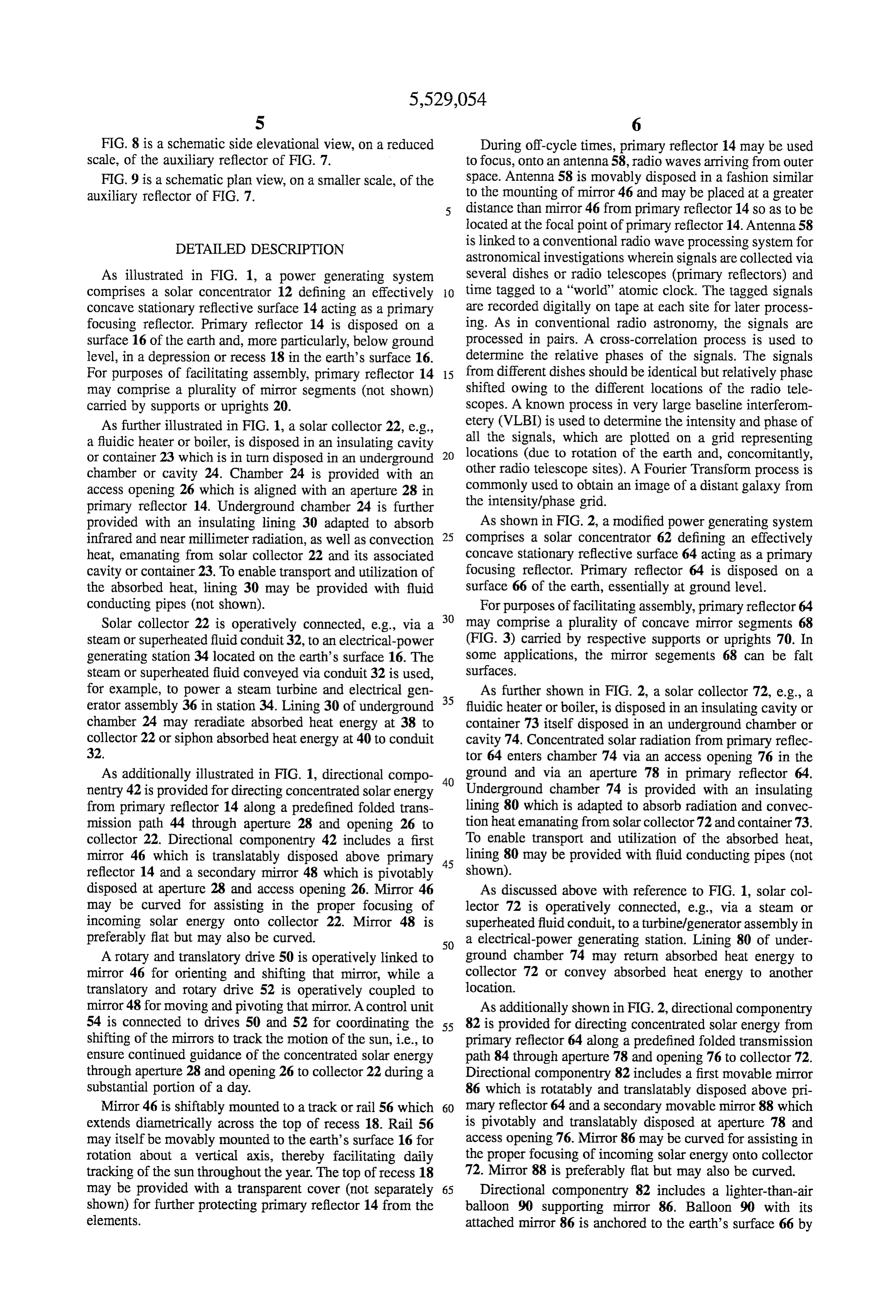
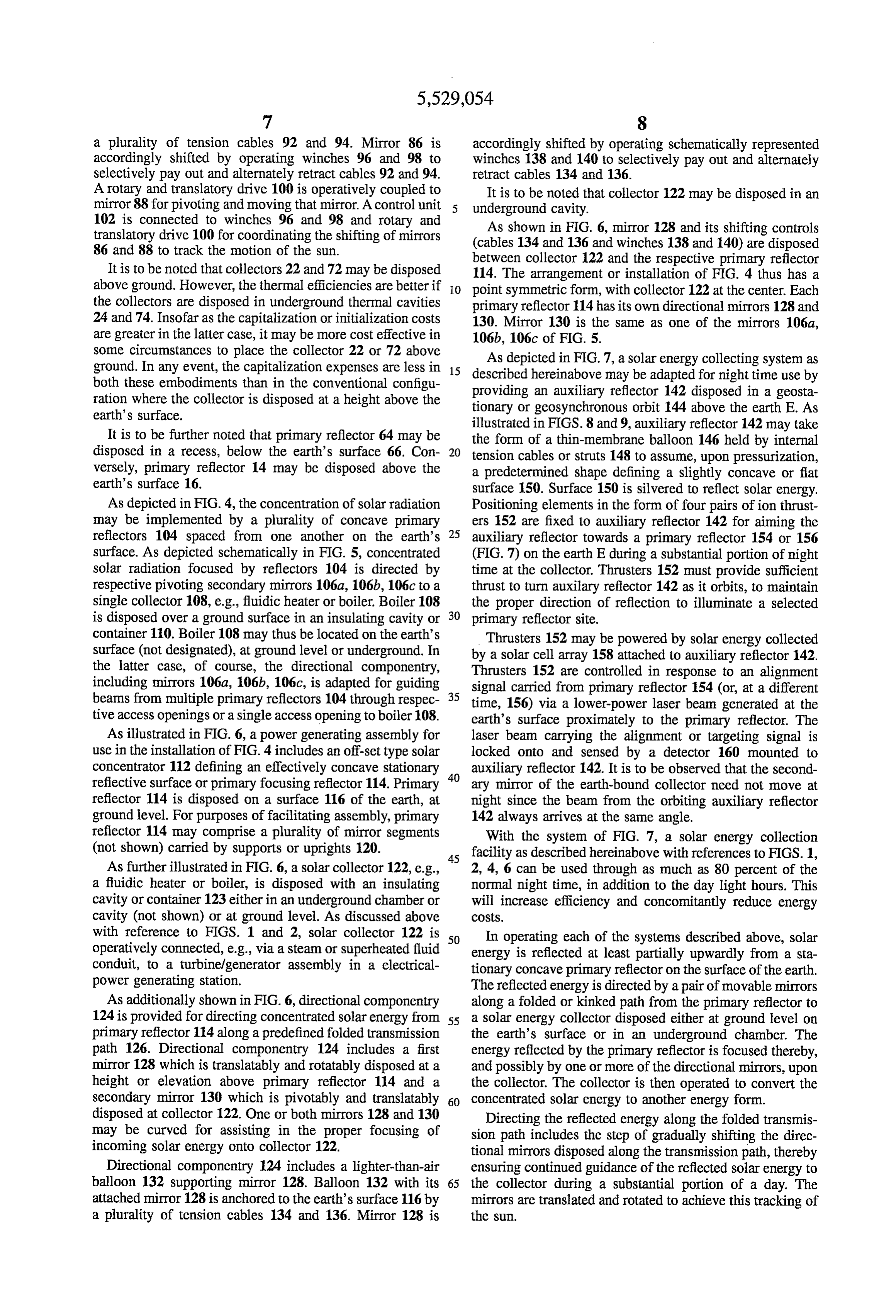
Pursuant to another feature of the present invention, the FIG. 1 is a diagram of a solar energy concentrating and directing of the reflected energy includes the step of shifting collecting system in accordance with the present invention. a plurality of mirrors disposed along the transmission path, FIG. 2 is a diagram of a modification of the solar energy thereby ensuring continued guidance of the reflected solar energy to the collector during a substantial portion of a day. 50 concentrating and collecting system of FIG. 1. This shifting may include the steps of translating at least one FIG. 3 is a partial schematic side elevational view of a of the mirrors and rotating another of the mirrors. More modification of a primary reflector illustrated in FIG. 2. preferably, the shifting includes rotating and translating both - FIG. 4 is a diagrammatic plan for an installation having a of the mirrors. The shifting may include the step of selec plurality of primary reflectors for concentrating incoming tively paying out and alternately retracting cables extending 55 solar radiation and a single collector. to a lighter-than-air balloon supporting one of the mirrors, FIG. 5 is a schematic perspective view of a solar energy that mirror being secured to the balloon. The mirror may be collector, showing incoming radiation directed along mul suspended by cables from the balloon. tiple folded transmission paths from a plurality of primary Pursuant to another feature of the present invention, the reflectors as illustrated in FIG. 4. method further comprises the step of absorbing heat radiated 60 FIG. 6 is a diagram similar to FIGS. 1 and 2, showing a from the collector. The absorption is accomplished, for modification of the solar energy concentrating and collecting example, by disposing heat conductive insulation along a systems of FIGS. 1 and 2, adapted for an installation as wall of the underground chamber. The insulation may rera depicted in FIG. 4.
diate heat back to the collector and or convey the heat to a FIG. 7 is a diagram of a further modification of a solar fluid moving through pipes embedded in the insulation. 65 energy concentrating and collecting system in accordance Pursuant to a further feature of the present invention, the with the present invention, showing an auxiliary reflector in method also comprises the step of converting, into an energy geosynchronous orbit.
Page 7
FIG. 8 is a schematic side elevational view, on a reduced During off-cycle times, primary reflector 14 may be used scale, of the auxiliary reflector of FIG. 7. to focus, onto an antenna 58, radio waves arriving from outer FIG.9 is a schematic plan view, on a smaller scale, of the space. Antenna 58 is movably disposed in a fashion similar auxiliary reflector of FIG. 7. to the mounting of mirror 46 and may be placed at a greater distance than mirror 46 from primary reflector 14 so as to be located at the focal point of primary reflector 14. Antenna 58
DETAILED DESCRIPTION is linked to a conventional radio wave processing system for astronomical investigations wherein signals are collected via
As illustrated in FIG. 1, a power generating system several dishes or radio telescopes (primary reflectors) and comprises a solar concentrator 12 defining an effectively 10 time tagged to a "world' atomic clock. The tagged signals concave stationary reflective surface 14 acting as a primary are recorded digitally on tape at each site for later process focusing reflector. Primary reflector 14 is disposed on a ing. As in conventional radio astronomy, the signals are surface 16 of the earth and, more particularly, below ground processed in pairs. A cross-correlation process is used to level, in a depression or recess 18 in the earth's surface 16. determine the relative phases of the signals. The signals For purposes of facilitating assembly, primary reflector 14 15 from different dishes should be identical but relatively phase may comprise a plurality of mirror segments (not shown) shifted owing to the different locations of the radio tele carried by supports or uprights 20. scopes. A known process in very large baseline interferom As further illustrated in FIG. 1, a solar collector 22, e.g., etery (VLBI) is used to determine the intensity and phase of a fluidic heater or boiler, is disposed in an insulating cavity all the signals, which are plotted on a grid representing or container 23 which is in turn disposed in an underground 20 locations (due to rotation of the earth and, concomitantly, chamber or cavity 24. Chamber 24 is provided with an other radio telescope sites). A Fourier Transform process is access opening 26 which is aligned with an aperture 28 in commonly used to obtain an image of a distant galaxy from primary reflector 14. Underground chamber 24 is further the intensity/phase grid.
provided with an insulating lining 30 adapted to absorb As shown in FIG. 2, a modified power generating system infrared and near millimeter radiation, as well as convection 25 comprises a solar concentrator 62 defining an effectively heat, emanating from solar collector 22 and its associated concave stationary reflective surface 64 acting as a primary cavity or container 23. To enable transport and utilization of focusing reflector. Primary reflector 64 is disposed on a the absorbed heat, lining 30 may be provided with fluid surface 66 of the earth, essentially at ground level. conducting pipes (not shown). For purposes of facilitating assembly, primary reflector 64 Solar collector 22 is operatively connected, e.g., via a 30 may comprise a plurality of concave mirror segments 68 steam or superheated fluid conduit 32, to an electrical-power (FIG. 3) carried by respective supports or uprights 70. In generating station 34 located on the earth's surface 16. The some applications, the mirror segements 68 can be falt steam or superheated fluid conveyed via conduit 32 is used, surfaces.
for example, to power a steam turbine and electrical gen 35 As further shown in FIG. 2, a solar collector 72, e.g., a erator assembly 36 in station 34. Lining 30 of underground fluidic heater or boiler, is disposed in an insulating cavity or chamber 24 may reradiate absorbed heat energy at 38 to container 73 itself disposed in an underground chamber or collector 22 or siphon absorbed heat energy at 40 to conduit cavity 74. Concentrated solar radiation from primary reflec 32. tor 64 enters chamber 74 via an access opening 76 in the As additionally illustrated in FIG. 1, directional compo ground and via an aperture 78 in primary reflector 64. nentry 42 is provided for directing concentrated solar energy 40 Underground chamber 74 is provided with an insulating from primary reflector 14 along a predefined folded trans lining 80 which is adapted to absorb radiation and convec mission path 44 through aperture 28 and opening 26 to tion heatemanating from solar collector 72 and container 73. collector 22. Directional componentry 42 includes a first To enable transport and utilization of the absorbed heat, mirror 46 which is translatably disposed above primary 45 lining 80 may be provided with fluid conducting pipes (not reflector 14 and a secondary mirror 48 which is pivotably shown).
disposed at aperture 28 and access opening 26. Mirror 46 As discussed above with reference to FIG. 1, solar col may be curved for assisting in the proper focusing of lector 72 is operatively connected, e.g., via a steam or incoming solar energy onto collector 22. Mirror 48 is superheated fluid conduit, to a turbine/generator assembly in preferably flat but may also be curved. 50 a electrical-power generating station. Lining 80 of under A rotary and translatory drive 50 is operatively linked to ground chamber 74 may return absorbed heat energy to mirror 46 for orienting and shifting that mirror, while a collector 72 or convey absorbed heat energy to another translatory and rotary drive 52 is operatively coupled to location.
mirror 48 for moving and pivoting that mirror. A control unit As additionally shown in FIG. 2, directional componentry 54 is connected to drives 50 and 52 for coordinating the 55 82 is provided for directing concentrated solar energy from shifting of the mirrors to track the motion of the sun, i.e., to primary reflector 64 along a predefined folded transmission ensure continued guidance of the concentrated solar energy path 84 through aperture 78 and opening 76 to collector 72. through aperture 28 and opening 26 to collector 22 during a Directional componentry 82 includes a first movable mirror substantial portion of a day. 86 which is rotatably and translatably disposed above pri Mirror 46 is shiftably mounted to a track or rail 56 which 60 mary reflector 64 and a secondary movable mirror 88 which extends diametrically across the top of recess 18. Rail 56 is pivotably and translatably disposed at aperture 78 and may itself be movably mounted to the earth's surface 16 for access opening 76. Mirror 86 may be curved for assisting in rotation about a vertical axis, thereby facilitating daily the proper focusing of incoming solar energy onto collector tracking of the sun throughout the year. The top of recess 18 72. Mirror 88 is preferably flat but may also be curved. may be provided with a transparent cover (not separately 65 Directional componentry 82 includes a lighter-than-air shown) for further protecting primary reflector 14 from the balloon 90 supporting mirror 86. Balloon 90 with its elements. attached mirror 86 is anchored to the earth's surface 66 by
Page 8
a plurality of tension cables 92 and 94. Mirror 86 is accordingly shifted by operating schematically represented accordingly shifted by operating winches 96 and 98 to winches 138 and 140 to selectively pay out and alternately selectively pay out and alternately retract cables 92 and 94. retract cables 134 and 136.
A rotary and translatory drive 100 is operatively coupled to It is to be noted that collector 122 may be disposed in an mirror 88 for pivoting and moving that mirror. A control unit underground cavity.
102 is connected to winches 96 and 98 and rotary and As shown in FIG. 6, mirror 128 and its shifting controls translatory drive 100 for coordinating the shifting of mirrors (cables 134 and 136 and winches 138 and 140) are disposed 86 and 88 to track the motion of the sun.
between collector 122 and the respective primary reflector
It is to be noted that collectors 22 and 72 may be disposed 114. The arrangement or installation of FIG. 4 thus has a above ground. However, the thermal efficiencies are better if O point symmetric form, with collector 122 at the center. Each the collectors are disposed in underground thermal cavities primary reflector 114 has its own directional mirrors 128 and 24 and 74. Insofar as the capitalization or initialization costs 130. Mirror 130 is the same as one of the mirrors 106a, are greater in the latter case, it may be more cost effective in 106b, 106c of FIG. 5.
some circumstances to place the collector 22 or 72 above As depicted in FIG. 7, a solar energy collecting system as ground. In any event, the capitalization expenses are less in 15 described hereinabove may be adapted for night time use by both these embodiments than in the conventional configu providing an auxiliary reflector 142 disposed in a geosta ration where the collector is disposed at a height above the tionary or geosynchronous orbit 144 above the earth E. As earth's surface.
illustrated in FIGS. 8 and 9, auxiliary reflector 142 may take
It is to be further noted that primary reflector 64 may be the form of a thin-membrane balloon 146 held by internal disposed in a recess, below the earth's surface 66. Con 20 tension cables or struts 148 to assume, upon pressurization, versely, primary reflector 14 may be disposed above the a predetermined shape defining a slightly concave or flat earth's surface 16. surface 150. Surface 150 is silvered to reflect solar energy. As depicted in FIG.4, the concentration of solar radiation Positioning elements in the form of four pairs of ion thrust may be implemented by a plurality of concave primary ers 152 are fixed to auxiliary reflector 142 for aiming the reflectors 104 spaced from one another on the earth's 25 auxiliary reflector towards a primary reflector 154 or 156 surface. As depicted schematically in FIG. 5, concentrated (FIG. 7) on the earth E during a substantial portion of night solar radiation focused by reflectors 104 is directed by time at the collector. Thrusters 152 must provide sufficient respective pivoting secondary mirrors 106a, 106b, 106c to a thrust to turn auxilary reflector 142 as it orbits, to maintain single collector 108, e.g., fluidic heater or boiler. Boiler 108 the proper direction of reflection to illuminate a selected is disposed over a ground surface in an insulating cavity or 30 primary reflector site.
container 110. Boiler 108 may thus be located on the earth's Thrusters 152 may be powered by solar energy collected surface (not designated), at ground level or underground. In by a solar cell array 158 attached to auxiliary reflector 142. the latter case, of course, the directional componentry, Thrusters 152 are controlled in response to an alignment including mirrors 106a, 106b, 106c, is adapted for guiding signal carried from primary reflector 154 (or, at a different beams from multiple primary reflectors 104 through respec 35 time, 156) via a lower-power laser beam generated at the tive access openings or a single access opening to boiler 108. earth's surface proximately to the primary reflector. The As illustrated in FIG. 6, a power generating assembly for laser beam carrying the alignment or targeting signal is use in the installation of FIG. 4 includes an off-set type solar locked onto and sensed by a detector 160 mounted to concentrator 112 defining an effectively concave stationary 40 auxiliary reflector 142. It is to be observed that the second reflective surface or primary focusing reflector 114. Primary ary mirror of the earth-bound collector need not move at reflector 114 is disposed on a surface 116 of the earth, at night since the beam from the orbiting auxiliary reflector ground level. For purposes of facilitating assembly, primary 142 always arrives at the same angle. reflector 114 may comprise a plurality of mirror segments With the system of FIG. 7, a solar energy collection (not shown) carried by supports or uprights 20. 45 facility as described hereinabove with references to FIGS. 1, As further illustrated in FIG. 6, a solar collector 122, e.g., 2, 4, 6 can be used through as much as 80 percent of the a fluidic heater or boiler, is disposed with an insulating normal night time, in addition to the day light hours. This cavity or container 123 either in an underground chamber or will increase efficiency and concomitantly reduce energy cavity (not shown) or at ground level. As discussed above COStS.
with reference to FIGS. 1 and 2, solar collector 122 is 50 In operating each of the systems described above, solar operatively connected, e.g., via a steam or superheated fluid energy is reflected at least partially upwardly from a sta conduit, to a turbine/generator assembly in a electrical tionary concave primary reflector on the surface of the earth. power generating station. The reflected energy is directed by a pair of movable mirrors As additionally shown in FIG. 6, directional componentry along a folded or kinked path from the primary reflector to 124 is provided for directing concentrated solar energy from 55 a solar energy collector disposed either at ground level on primary reflector 114 along a predefined folded transmission the earth's surface or in an underground chamber. The path 126. Directional componentry 124 includes a first energy reflected by the primary reflector is focused thereby, mirror 128 which is translatably and rotatably disposed at a and possibly by one or more of the directional mirrors, upon height or elevation above primary reflector 114 and a the collector. The collector is then operated to convert the secondary mirror 130 which is pivotably and translatably 60 concentrated solar energy to another energy form. disposed at collector 122. One or both mirrors 128 and 130 Directing the reflected energy along the folded transmis may be curved for assisting in the proper focusing of sion path includes the step of gradually shifting the direc incoming solar energy onto collector 122. tional mirrors disposed along the transmission path, thereby Directional componentry 124 includes a lighter-than-air ensuring continued guidance of the reflected solar energy to balloon 132 supporting mirror 128. Balloon 132 with its 65 the collector during a substantial portion of a day. The attached mirror 128 is anchored to the earth's surface 116 by mirrors are translated and rotated to achieve this tracking of a plurality of tension cables 134 and 136. Mirror 128 is the Sun.
Page 9
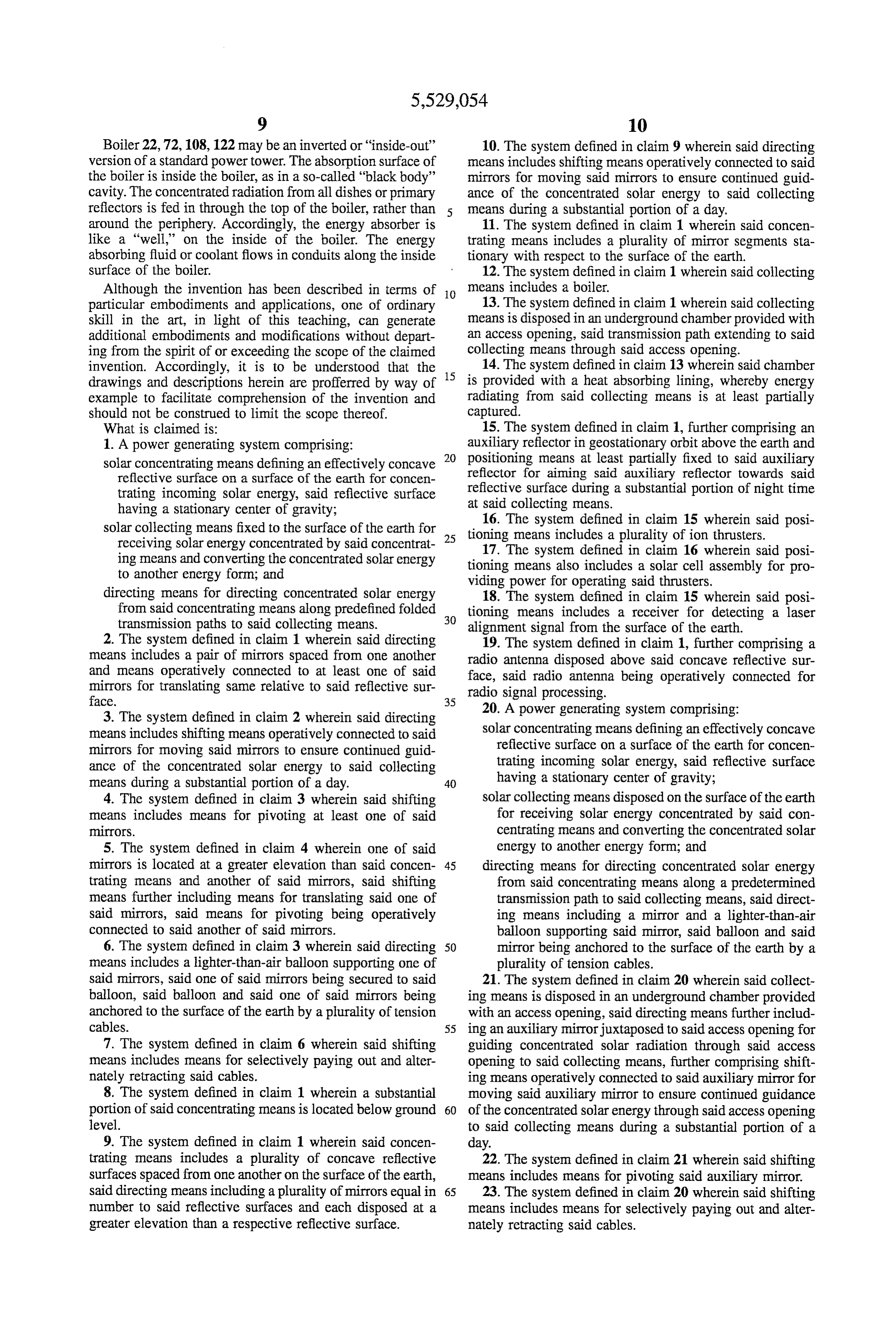
Boiler 22,72,108,122 may be an inverted or "inside-out' 10. The system defined in claim 9 wherein said directing version of a standard power tower. The absorption surface of means includes shifting means operatively connected to said the boiler is inside the boiler, as in a so-called "black body' mirrors for moving said mirrors to ensure continued guid cavity. The concentrated radiation from all dishes or primary ance of the concentrated solar energy to said collecting reflectors is fed in through the top of the boiler, rather than 5 means during a substantial portion of a day. around the periphery. Accordingly, the energy absorber is 11. The system defined in claim 1 wherein said concen like a "well," on the inside of the boiler. The energy trating means includes a plurality of mirror segments sta absorbing fluid or coolant flows in conduits along the inside tionary with respect to the surface of the earth. surface of the boiler. 12. The system defined in claim 1 wherein said collecting Although the invention has been described in terms of 10 means includes a boiler.
particular embodiments and applications, one of ordinary 13. The system defined in claim 1 wherein said collecting skill in the art, in light of this teaching, can generate means is disposed in an underground chamber provided with additional embodiments and modifications without depart an access opening, said transmission path extending to said ing from the spirit of or exceeding the scope of the claimed collecting means through said access opening. invention. Accordingly, it is to be understood that the 15 14. The system defined in claim 13 wherein said chamber drawings and descriptions herein are profferred by way of is provided with a heat absorbing lining, whereby energy example to facilitate comprehension of the invention and radiating from said collecting means is at least partially should not be construed to limit the scope thereof. captured.
What is claimed is: 15. The system defined in claim 1, further comprising an 1. A power generating system comprising: auxiliary reflector in geostationary orbit above the earth and positioning means at least partially fixed to said auxiliary solar concentrating means defining an effectively concave 20 reflector reflective surface on a surface of the earth for concen for aiming said auxiliary reflector towards said trating incoming solar energy, said reflective surface reflective surface during a substantial portion of night time having a stationary center of gravity; at said collecting means.
16. The system defined in claim 15 wherein said posi solar collecting means fixed to the surface of the earth for 25 tioning receiving Solar energy concentrated by said concentrat means includes a plurality of ion thrusters. ing means and converting the concentrated Solar energy 17. The system defined in claim 16 wherein said posi to another energy form; and tioning means also includes a solar cell assembly for pro viding power for operating said thrusters.
directing means for directing concentrated solar energy 18. The system defined in claim 15 wherein said posi from said concentrating means along predefined folded tioning means includes a receiver for detecting a laser transmission paths to said collecting means. 30 alignment signal from the surface of the earth. 2. The system defined in claim 1 wherein said directing 19. The system defined in claim 1, further comprising a means includes a pair of mirrors spaced from one another radio antenna disposed above said concave reflective sur and means operatively connected to at least one of said face, said radio antenna being operatively connected for mirrors for translating same relative to said reflective sur radio signal processing.
face. 35 3. The system defined in claim 2 wherein said directing 20. A power generating system comprising: means includes shifting means operatively connected to said solar concentrating means defining an effectively concave mirrors for moving said mirrors to ensure continued guid reflective surface on a surface of the earth for concen ance of the concentrated solar energy to said collecting trating incoming solar energy, said reflective surface means during a Substantial portion of a day. 40 having a stationary center of gravity; 4. The system defined in claim 3 wherein said shifting solar collecting means disposed on the surface of the earth means includes means for pivoting at least one of said for receiving solar energy concentrated by said con mirrors. centrating means and converting the concentrated solar 5. The system defined in claim 4 wherein one of said energy to another energy form; and mirrors is located at a greater elevation than said concen- 45 directing means for directing concentrated solar energy trating means and another of said mirrors, said shifting from said concentrating means along a predetermined means further including means for translating said one of transmission path to said collecting means, said direct said mirrors, said means for pivoting being operatively ing means including a mirror and a lighter-than-air connected to said another of said mirrors. balloon supporting said mirror, said balloon and said 6. The system defined in claim 3 wherein said directing 50 mirror being anchored to the surface of the earth by a means includes a lighter-than-air balloon supporting one of plurality of tension cables. said mirrors, said one of said mirrors being secured to said 21. The system defined in claim 20 wherein said collect balloon, said balloon and said one of said mirrors being ing means is disposed in an underground chamber provided anchored to the surface of the earth by a plurality of tension with an access opening, said directing means further includ cables. 55 ing an auxiliary mirror juxtaposed to said access opening for 7. The system defined in claim 6 wherein said shifting guiding concentrated solar radiation through said access means includes means for selectively paying out and alter opening to said collecting means, further comprising shift nately retracting said cables. ing means operatively connected to said auxiliary mirror for 8. The system defined in claim 1 wherein a substantial moving said auxiliary mirror to ensure continued guidance portion of said concentrating means is located below ground 60 of the concentrated solar energy through said access opening level. to said collecting means during a substantial portion of a 9. The system defined in claim 1 wherein said concen day.
trating means includes a plurality of concave reflective 22. The system defined in claim 21 wherein said shifting surfaces spaced from one another on the surface of the earth, means includes means for pivoting said auxiliary mirror. said directing means including a plurality of mirrors equal in 65 23. The system defined in claim 20 wherein said shifting number to said reflective surfaces and each disposed at a means includes means for selectively paying out and alter greater elevation than a respective reflective surface. nately retracting said cables.
Page 10
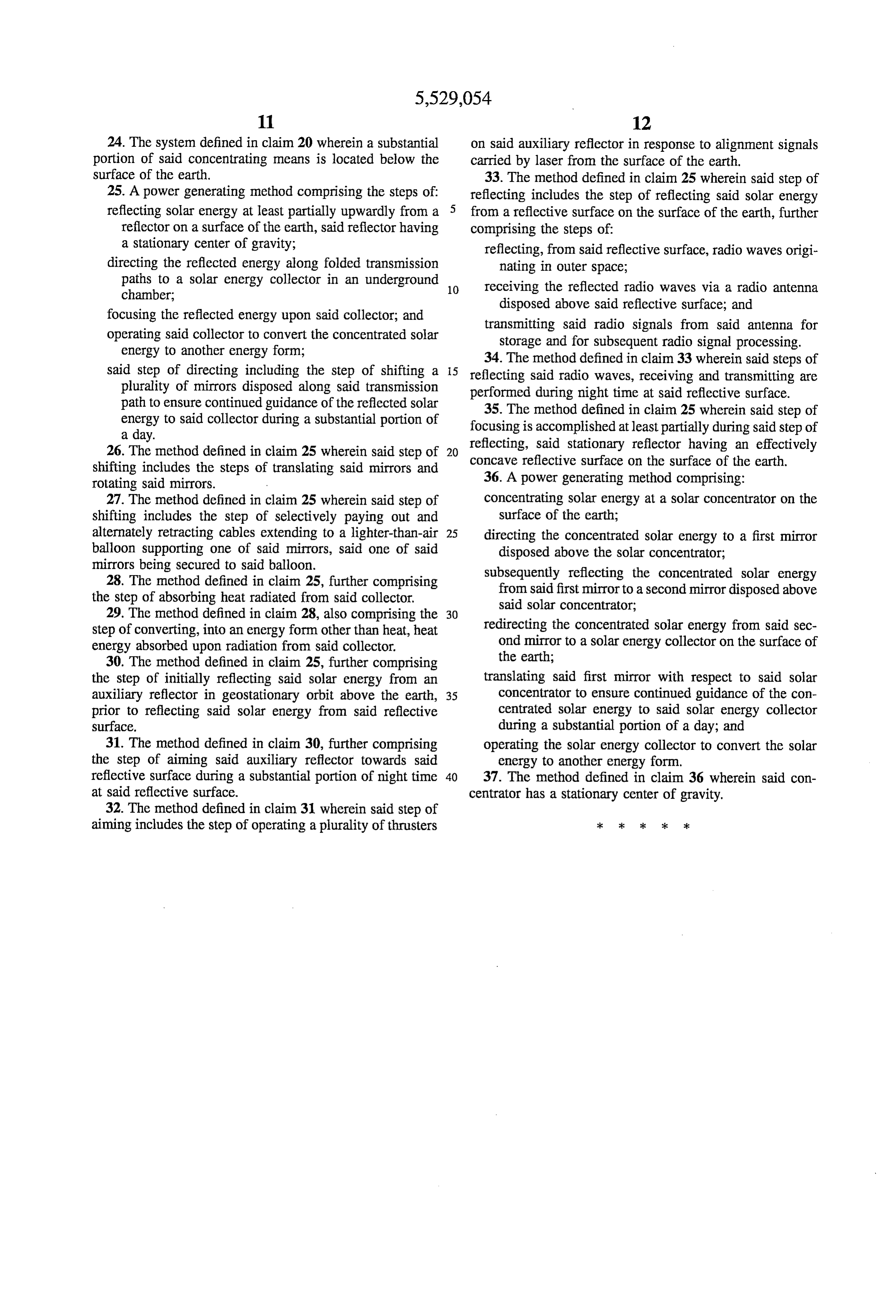
24. The system defined in claim 20 wherein a substantial on said auxiliary reflector in response to alignment signals portion of said concentrating means is located below the carried by laser from the surface of the earth. surface of the earth. 33. The method defined in claim 25 wherein said step of 25. A power generating method comprising the steps of: reflecting includes the step of reflecting said solar energy reflecting solar energy at least partially upwardly from a 5 from a reflective surface on the surface of the earth, further reflector on a surface of the earth, said reflector having comprising the steps of:
a stationary center of gravity; reflecting, from said reflective surface, radio waves origi directing the reflected energy along folded transmission nating in outer space;
paths to a solar energy collector in an underground 10 receiving the reflected radio waves via a radio antenna chamber, disposed above said reflective surface; and focusing the reflected energy upon said collector; and transmitting said radio signals from said antenna for operating said collector to convert the concentrated solar storage and for subsequent radio signal processing. energy to another energy form; 34. The method defined in claim 33 wherein said steps of said step of directing including the step of shifting a 15 reflecting said radio waves, receiving and transmitting are plurality of mirrors disposed along said transmission performed during night time at said reflective surface. path to ensure continued guidance of the reflected solar 35. The method defined in claim 25 wherein said step of energy to said collector during a substantial portion of focusing is accomplished at least partially during said step of a day. reflecting, said stationary reflector having an effectively 26. The method defined in claim 25 wherein said step of concave reflective
surface on the surface of the earth.
shifting includes the steps of translating said mirrors and 36. A power generating method comprising: rotating said mirrors.
27. The method defined in claim 25 wherein said step of concentrating solar energy at a solar concentrator on the shifting includes the step of selectively paying out and surface of the earth;
alternately retracting cables extending to a lighter-than-air 25 directing the concentrated solar energy to a first mirror balloon supporting one of said mirrors, said one of said disposed above the solar concentrator; mirrors being secured to said balloon. subsequently reflecting the concentrated solar energy 28. The method defined in claim 25, further comprising from said first mirror to a second mirror disposed above the step of absorbing heat radiated from said collector. said solar concentrator; 29. The method defined in claim 28, also comprising the 30 step of converting, into an energy form other than heat, heat redirecting the concentrated solar energy from said sec energy absorbed upon radiation from said collector. ond mirror to a solar energy collector on the surface of 30. The method defined in claim 25, further comprising the earth;
the step of initially reflecting said solar energy from an translating said first mirror with respect to said solar auxiliary reflector in geostationary orbit above the earth, 35 concentrator to ensure continued guidance of the con prior to reflecting said solar energy from said reflective centrated solar energy to said solar energy collector surface. during a substantial portion of a day; and 31. The method defined in claim 30, further comprising operating the solar energy collector to convert the solar the step of aiming said auxiliary reflector towards said energy to another energy form. reflective surface during a substantial portion of night time 40 37. The method defined in claim 36 wherein said con at said reflective surface. centrator has a stationary center of gravity. 32. The method defined in claim 31 wherein said step of aiming includes the step of operating a plurality of thrusters ck ki k k k
Provenance
- Collection
- Cited prior art
- Original PDF
- patentimages.storage.googleapis.com →
- Filed
- 1994-06-20
- Pages
- 10
- Method
- pdftotext (the PDF's own text layer) + pdftoppm 300dpi page scans
- Source
- Google Patents bibliographic record
- Granted
- 1996-06-25
- Inventors
- Neil C. Shoen
- Transcribed from
- patentimages.storage.googleapis.com →