patent · US5113845
Portable solar heating device and heating process utilizing solar energy
19 May 1992
Page 1 — bibliographic record
United States Patent (19) 11 Patent Number: 5,113,845 Nix 45 Date of Patent: May 19, 1992 (54) PORTABLESOLAR HEATING DEVICE AND Primary Examiner-Carroll B. Dority HEATING PROCESS UILIZING SOLAR Attorney, Agent, or Firm-Robert W. Beach ENERGY 57) ABSTRACT 76 Inventor: Martin E. Nix, P.O. Box 95173, A concave parabolic reflector receiving solar rays di Seattle, Wash. 98145-2173 rectly and by reflection from an angularly adjustable (21) Appl. No.: 585,870 auxiliary collecting plate and from a stationary side 22 Filed: Sep. 20, 1990 plate reflects such solar rays to a line focus at which material to be heated is located, which may be liquid, 51) Int. C. ........................r F24, 2/O2 gas or food to be cooked. Such food may be placed in a 52 U.S. C. ................. a a a 126/451; 126/439 container having a cast iron heat sink cover and such 58 Field of Search ........................ 126/451, 438, 439 container may be an inner container enclosed in an 56) References Cited outer container spaced from the inner container a dis
tance sufficient to form a cooking chamber for cooking food in the outer container at a temperature lower than 2,859,745 l/1958 Von Brudersdorff .............. 126/45 the temperature within the inner container. The degree 3,938,497 2/1976 Andrassy ............................ 126/270 of tilt of the auxiliary reflecting plate can be adjusted 4,083,357 4/1978 Fischer ................................ 26/45 depending on the elevation of the sun and such plate can 4,236,508 12/1980 Kerr .................................... 126/451 be swung to horizontal position to serve as a dining 4,262,660 4/198i Ilich .................................... 26/451 table.
4,546,757 10/1985 Jakahi.................................. 126/439 4,597,377 7/1986 Melamed ............................. 126/438 13 Claims, 6 Drawing Sheets
Page 2
Drawing sheet — no readable text.
Page 3
Drawing sheet — no readable text.
Page 4
Drawing sheet — no readable text.
Page 5
Drawing sheet — no readable text.
Page 6
Drawing sheet — no readable text.
Page 7
Drawing sheet — no readable text.
Page 8
collected without correspondingly increasing the size
PORTABLE SOLAR HEATING DEVICE AND of the apparatus and still enabling the solar rays col HEATING PROCESS UTILIZING SOLAR ENERGY lected over such collection area to be concentrated effectively on a heating or cooking focal area of reason
BACKGROUND OF THE INVENTION able size.
1. Field of the Invention Another object of the invention is to make use of This invention relates to a solar heating device of the stray solar rays and diffused light either by directing small portable type the primary use of which is cooking, such rays and light onto a concentrating reflector or and to a heating process utilizing solar energy. receiver to be heated and/or converting such stray rays 2. Prior Art O and diffused light into useful heat. While this invention can be used for heating liquids It is also an object to utilize solar rays effectively for and gases, such as air, the principal utility of the device heating purposes without the necessity of providing a and process is for cooking. concentrating reflector driven through a predetermined Prior solar cookers have been of four principal types. 15 path to intercept solar rays more effectively. The simplest type of prior solar cooker is of the box An incidental object is to conserve the energy in solar type such as represented by Kerr U.S. Pat. No. rays, whether in the form of light or heat, and utilize it 4,236,508, issued Dec. 2, 1980, which includes a box beneficially.
open at the top for holding food to be cooked and hav More specifically, it is an object to provide an effec ing a cover hingedly attached to one upper edge of the tive support for food to be cooked at a line focus of a box for reflecting solar rays down into the open top of concave concentrating reflector for solar rays. the box oven. With such a box, the rays of the sun are Another object is to provide a support for food to be not sufficiently concentrated to create a temperature cooked in the form of an oven located at the line focus high enough to cook food effectively. of a solar ray concentrating reflector. The second type of solar cooker is the concentrated 25 An additional object is to provide effective and eco focus type represented by the Von Brudersdorff U.S. nomical insulation for food to be cooked carried by a Pat. No. 2,859,745, issued Nov. 11, 1958. The solar rays food support.
are concentrated by a double-curved concave reflector which concentrates the solar rays on a relatively small beAconverted further object is to provide a solar cooker that can readily to provide a dining table.
focus area so that either the size of the cooking area is It is also an object to provide a solar cooker which is smaller than desirable or the double-curved concave 30 reflector must be larger than desirable. compact in relation to its cooking capacity. The foregoing
A third type of prior solar cooker is shown in the cooker having a concave objects can be accomplished by a solar Andrassy U.S. Pat. No. 3,938,497, issued Feb. 17, 1976, solar reflector for concentrating which directs solar rays onto a plate having a compara rays at a line focus and which has an auxiliary flat tively large area both by a cylindrically concave type of 35 reflector for enlarging the area for collecting solar rays reflector and by flat plates. The plate to be heated may and directing them onto a concave solar ray concentrat have heat-collecting fins and transfers heat to food to be ing reflector. An oven for containing food to be cooked is mounted in a position for holding food substantially at cooked or to water to be heated.
The fourth type of solar cooker is of the line focus the fects line focus to which the concentrating reflector re the solar rays. Preferably, such auxiliary flat re type which is the type to which the present invention relates. Line focus cookers are represented by the Fi flector is of an area greater than the collection area of scher U.S. Pat. No. 4,083,357, issued Apr. 11, 1978, the the solar ray concentrating reflector and is mounted for Ilich U.S. Pat. No. 4,262,660, issued Apr. 21, 1981, and movement relative to such concentrating reflector both the Takeuchi et al. U.S. Pat. No. 4,442,828, issued Apr. to reflect solar rays most effectively onto the concen 17, 1984. The cookers of the Fischer and Ilich patents 45 trating reflector and into a horizontal position covering have reflectors of parabolic shape, whereas it is not the concentrating reflector and suitable for use as a clear whether the composite reflector of the Takeuchi dining table.
et al. patent is of parabolic shape or of cylindrically BRIEF DESCRIPTION OF THE DRAWINGS curved shape like the reflector of the Andrassy patent.
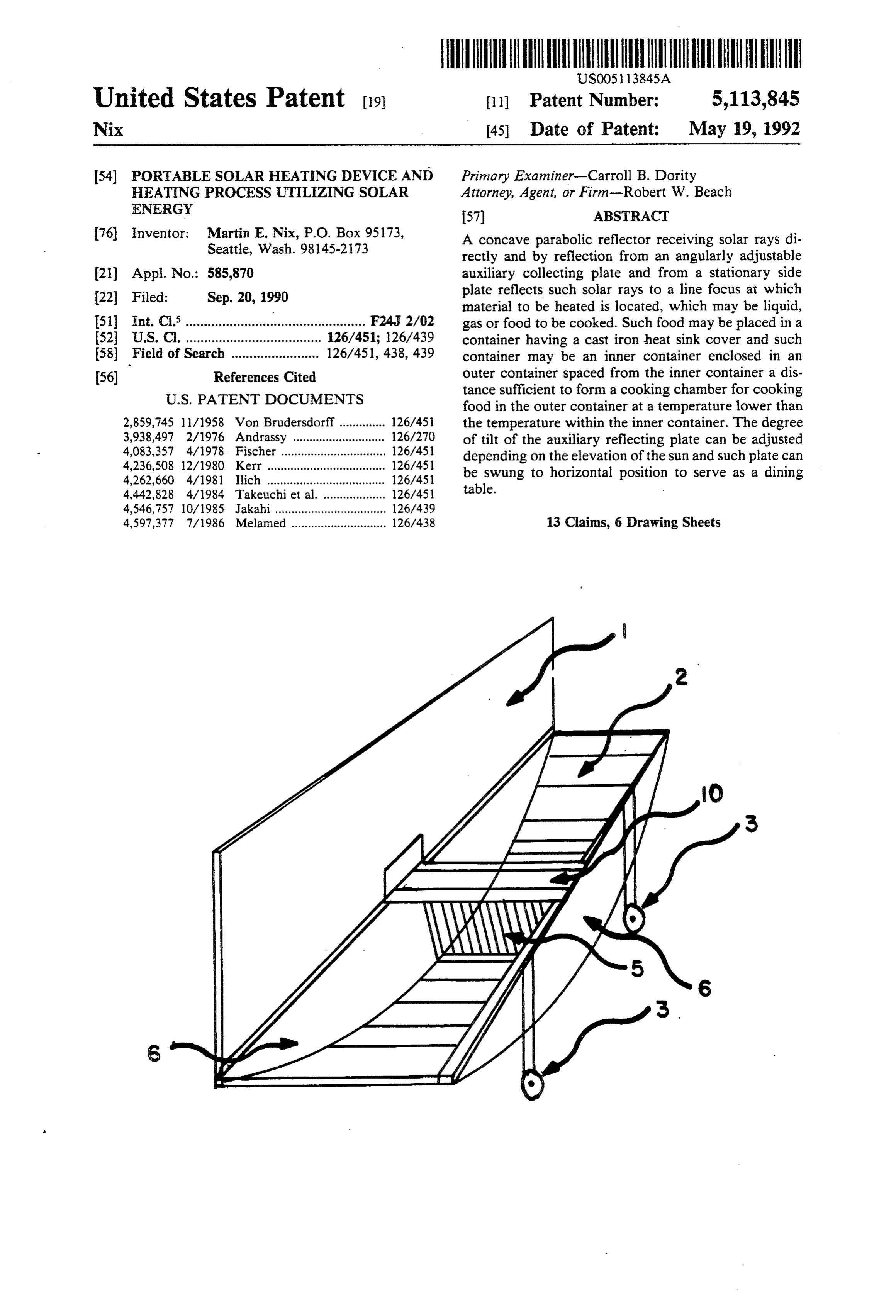
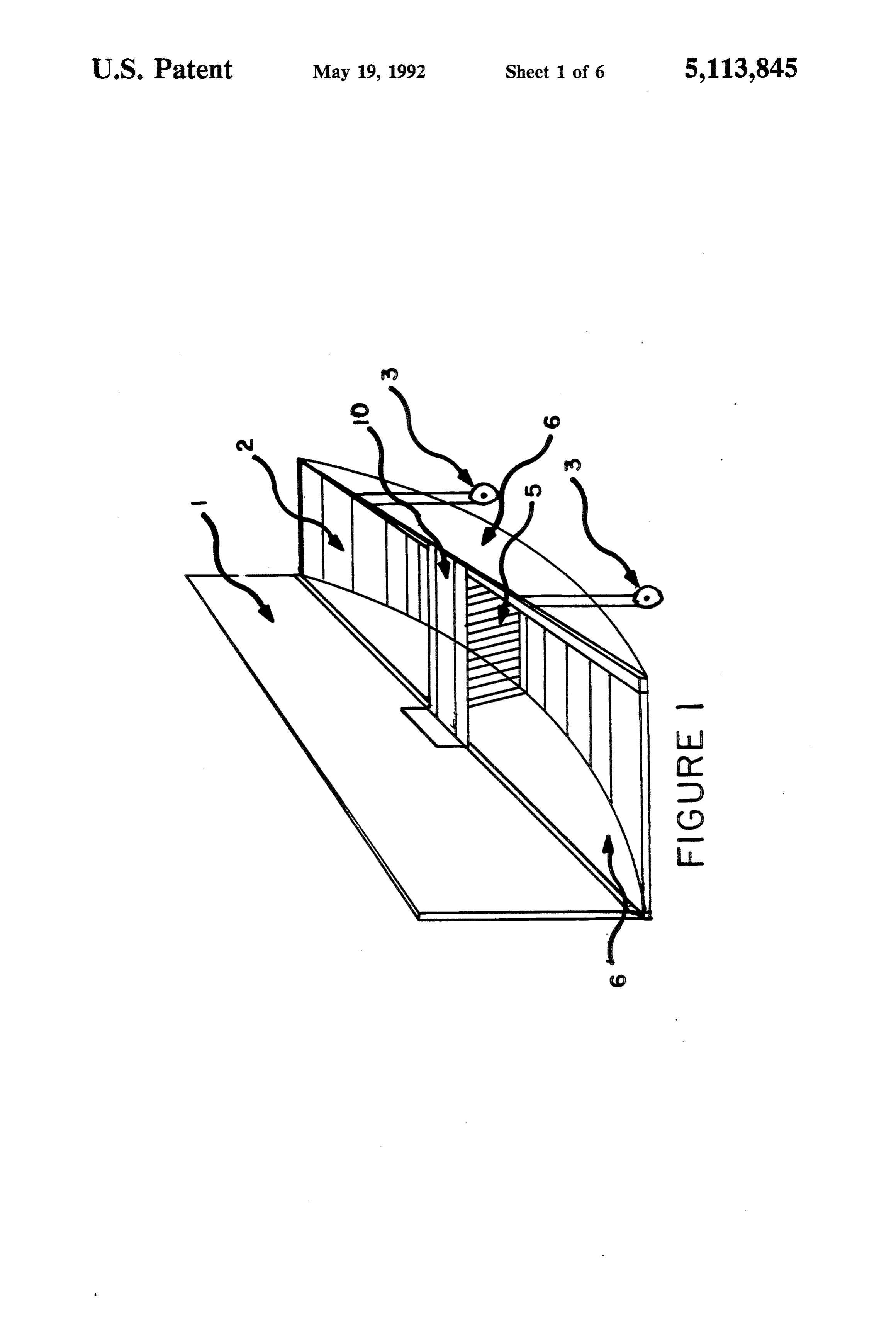
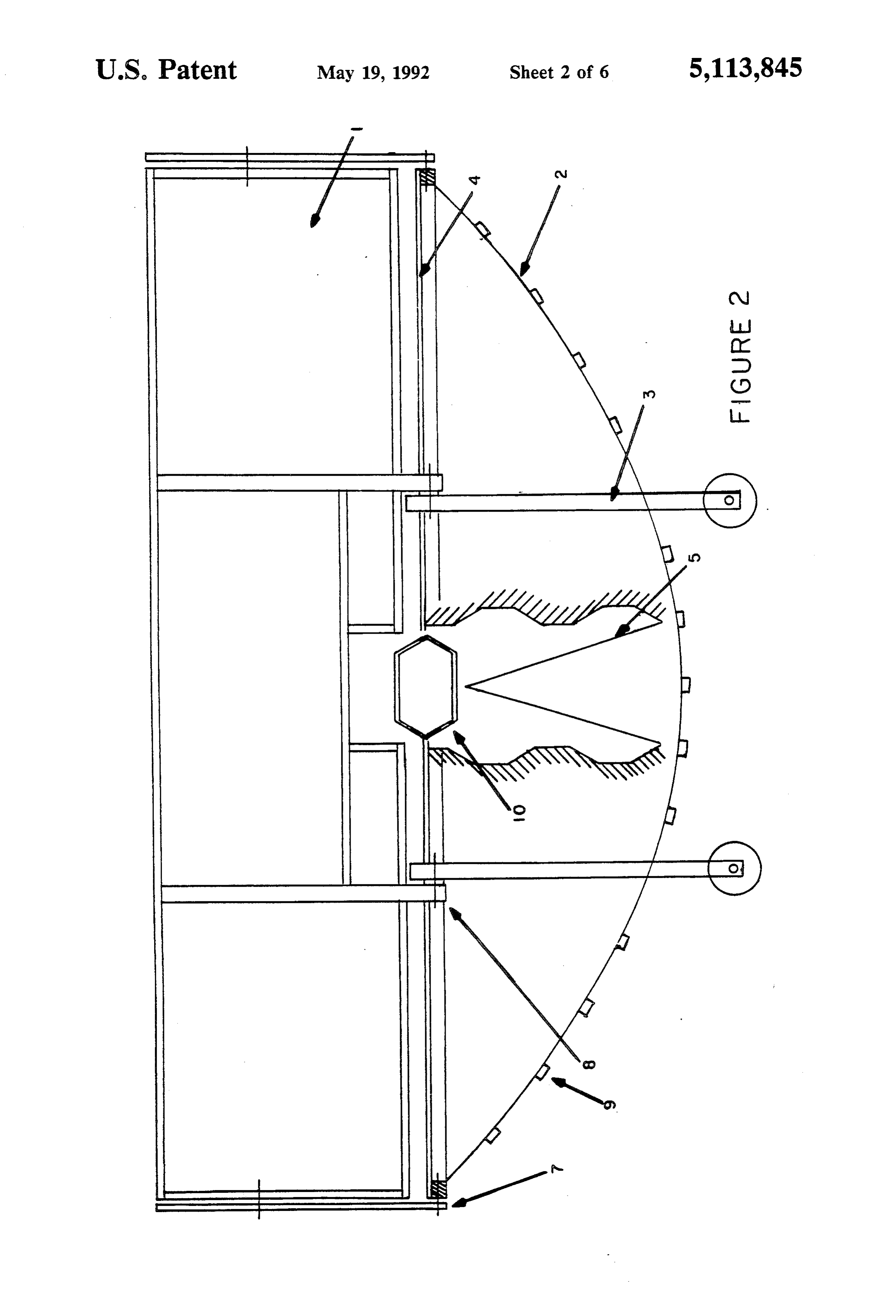
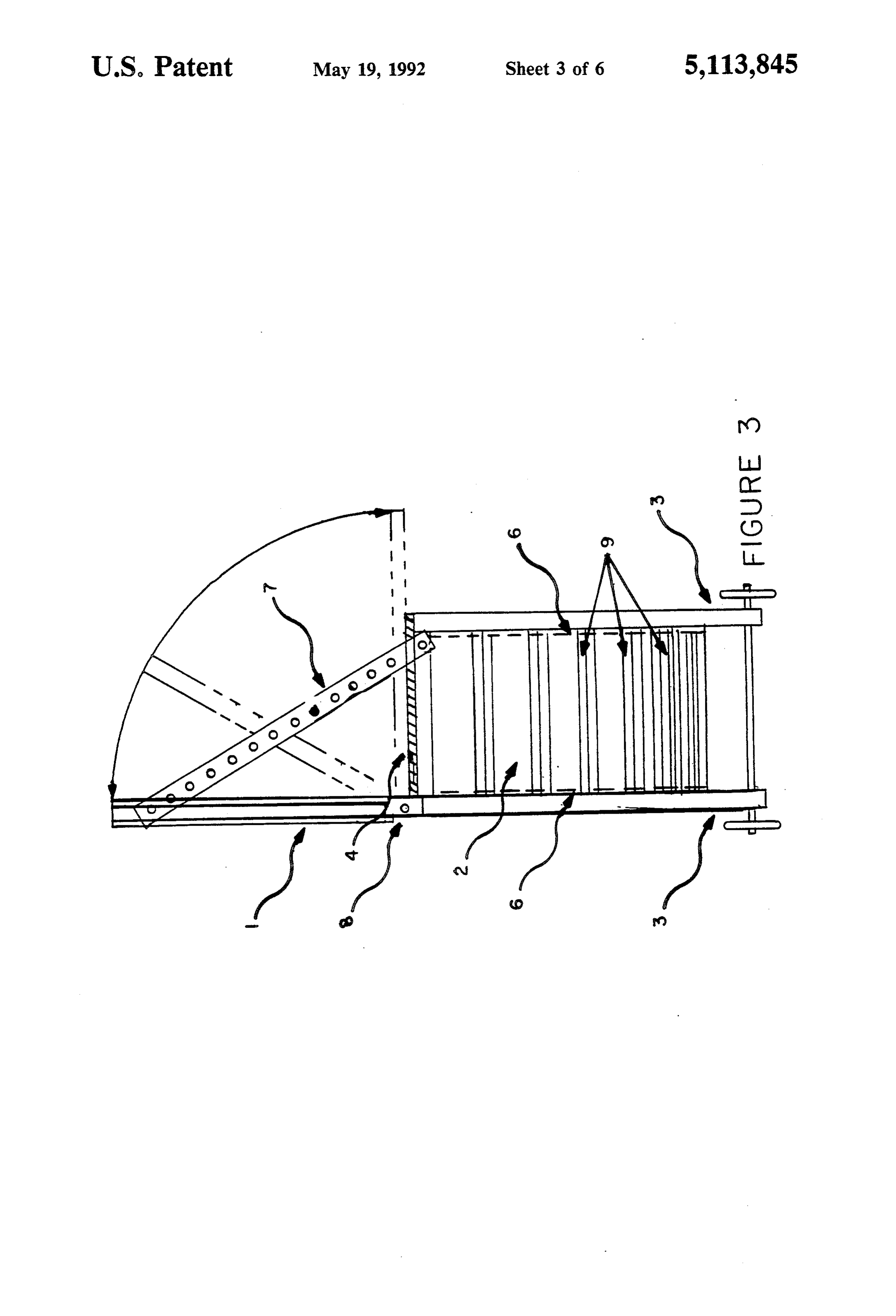
in any event, the reflectors of all of the Fischer, Ilich 50 FIG. 1 is a top perspective of a portable solar heating and Takeuchi et al. patents concentrate solar rays along device according to the present invention. a line focus, as distinguished from an area focus as uti FIG. 2 is a side elevation of such heating device with lized by the cooker of the Andrassy patent, or from a parts broken away, and FIG. 3 is an end elevation of more localized focus as in the cooker of the Von Bru such heating device.
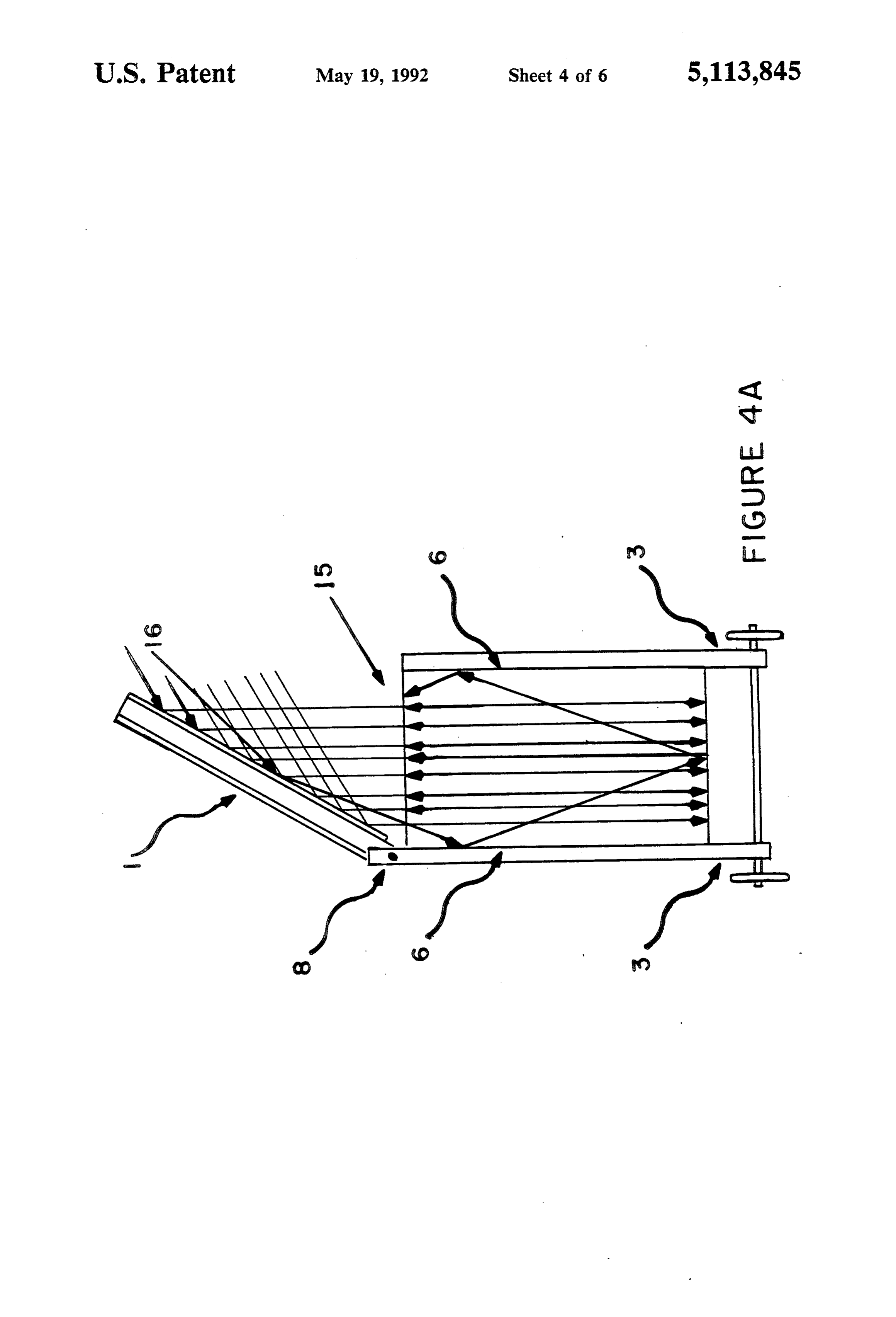
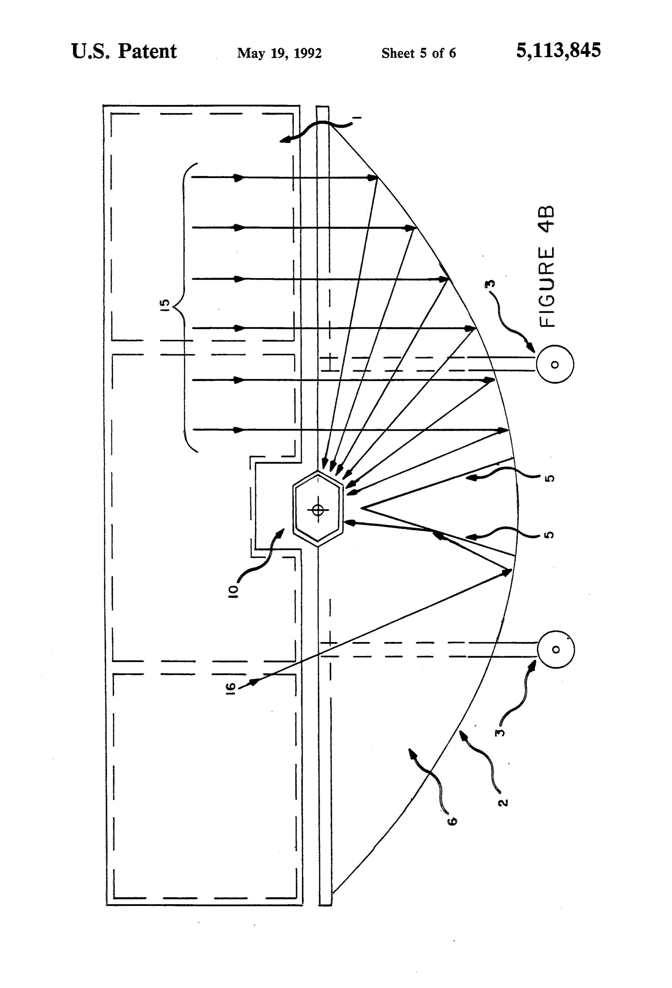
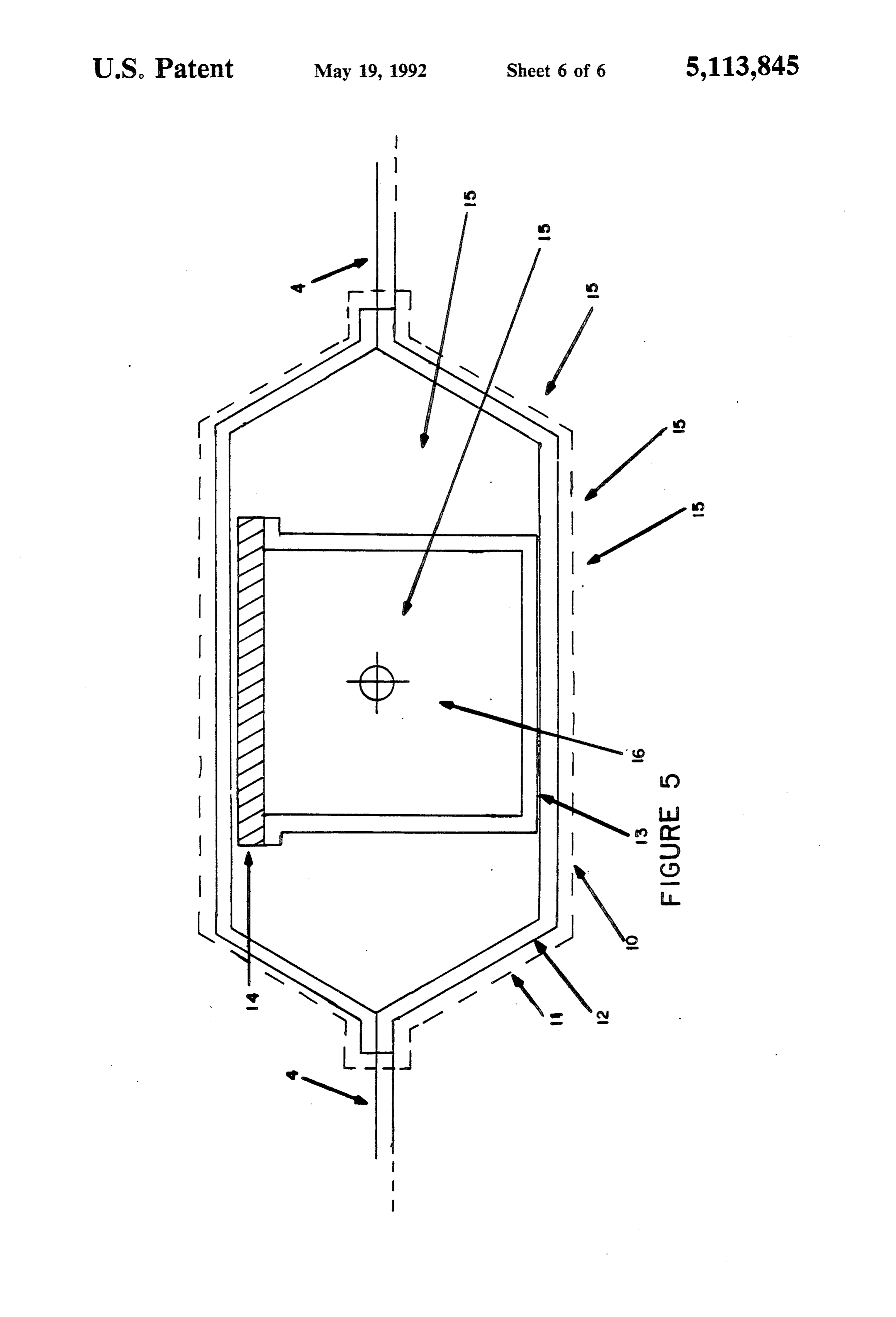
dersdorff patent having a double-curved concave re 55 FIG. 4A is a somewhat diagrammatic transverse flector. vertical section taken through the portable solar heating A disadvantage of the line focus type of solar cookers device illustrating the functioning of its components, shown in the Fischer, Ilich and Takeuchi et al. patents and FIG. 4B is a somewhat diagrammatic longitudinal is that they utilize only direct solar rays collected over vertical section through the solar heating device also an area substantially equal to the area of the reflector 60 illustrating the functioning of its components. which requires much larger apparatus to obtain a prede FIG. 5 is an enlarged detail vertical section through termined heating effect than is obtained by the device of the oven component of the solar heating device. the present invention. DETALED DESCRIPTION SUMMARY OF THE INVENTION 65 FIG. 1 shows generally the structure of the portable A principal object of the present invention is to in solar heating device as including an auxiliary flat reflec crease the effectiveness of solar heating apparatus by tor plate 1 swingable as indicated in FIG. 3 about its increasing the collection area over which solar rays are lower edge which extends along the major chord of the
Page 9
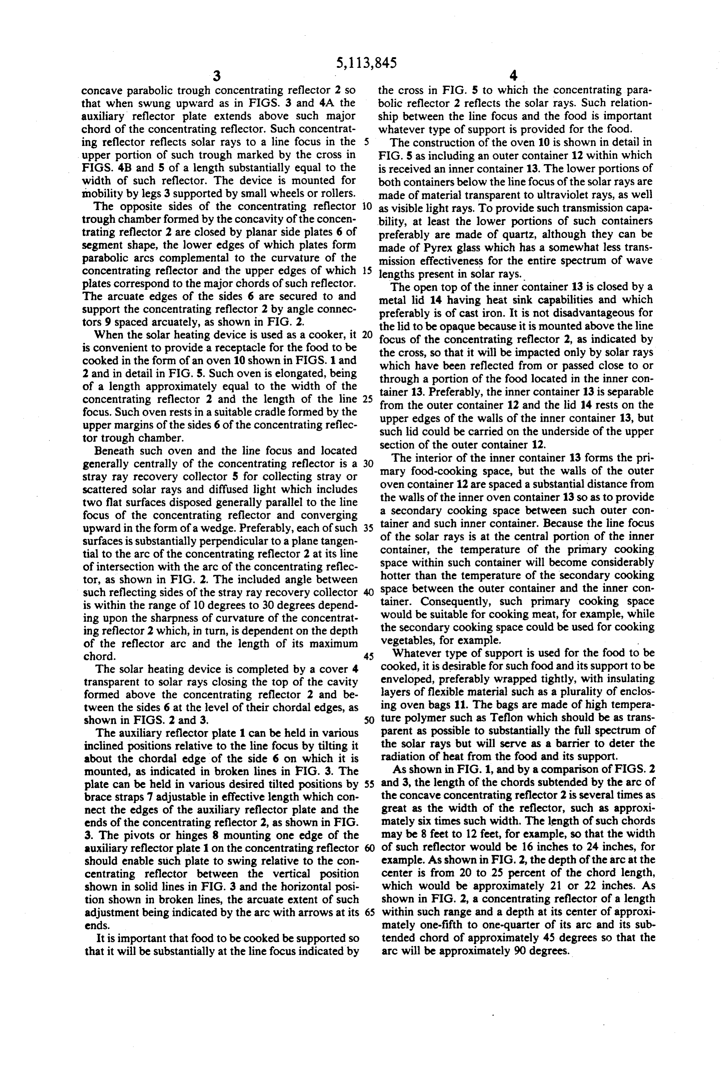
concave parabolic trough concentrating reflector 2 so the cross in FIG. 5 to which the concentrating para that when swung upward as in FIGS. 3 and 4A the bolic reflector 2 reflects the solar rays. Such relation auxiliary reflector plate extends above such major ship between the line focus and the food is important chord of the concentrating reflector. Such concentrat whatever type of support is provided for the food. ing reflector reflects solar rays to a line focus in the 5 The construction of the oven 10 is shown in detail in upper portion of such trough marked by the cross in FIG. 5 as including an outer container 12 within which FIGS. 4B and 5 of a length substantially equal to the is received an inner container 13. The lower portions of width of such reflector. The device is mounted for both containers below the line focus of the solar rays are mobility by legs 3 supported by small wheels or rollers. made of material transparent to ultraviolet rays, as well The opposite sides of the concentrating reflector 10 as visible light rays. To provide such transmission capa trough chamber formed by the concavity of the concen bility, at least the lower portions of such containers trating reflector 2 are closed by planar side plates 6 of preferably are made of quartz, although they can be segment shape, the lower edges of which plates form made of Pyrex glass which has a somewhat less trans parabolic arcs complemental to the curvature of the mission effectiveness for the entire spectrum of wave concentrating reflector and the upper edges of which 15 lengths present in solar rays.
plates correspond to the major chords of such reflector. The open top of the inner container 13 is closed by a The arcuate edges of the sides 6 are secured to and metal lid 14 having heat sink capabilities and which support the concentrating reflector 2 by angle connec preferably is of cast iron. It is not disadvantageous for tors 9 spaced arcuately, as shown in FIG. 2.
When the solar heating device is used as a cooker, it 20 the lid to be opaque because it is mounted above the line focus of the concentrating reflector 2, as indicated by is convenient to provide a receptacle for the food to be the cross, so that it will be impacted only by solar rays cooked in the form of an oven 10 shown in FIGS. 1 and which have been reflected from or passed close to or 2 and in detail in FIG. 5. Such oven is elongated, being through a portion of the food located in the inner con of a length approximately equal to the width of the tainer 13. Preferably, the inner container 13 is separable concentrating reflector 2 and the length of the line 25 from the outer container 12 and the lid 14 rests on the focus. Such oven rests in a suitable cradle formed by the upper edges of the walls of the inner container 13, but upper margins of the sides 6 of the concentrating reflec such lid could be carried on the underside of the upper tor trough chamber. section of the outer container 12. Beneath such oven and the line focus and located generally centrally of the concentrating reflector is a 30 mary The interior of the inner container 13 forms the pri stray ray recovery collector 5 for collecting stray or food-cooking space, but the walls of the outer scattered solar rays and diffused light which includes the walls of the 12 oven container are spaced a substantial distance from inner oven container 13 so as to provide two flat surfaces disposed generally parallel to the line a secondary cooking space between such outer con focus of the concentrating reflector and converging tainer and such inner container. Because the line focus upward in the form of a wedge. Preferably, each of such 35 surfaces is substantially perpendicular to a plane tangen of the solar rays is at the central portion of the inner tial to the arc of the concentrating reflector 2 at its line container, the temperature of the primary cooking of intersection with the arc of the concentrating reflec space within such container will become considerably tor, as shown in FIG. 2. The included angle between hotter than the temperature of the secondary cooking space between the outer container and the inner con such reflecting sides of the stray ray recovery collector 40 tainer.
is within the range of 10 degrees to 30 degrees depend Consequently, such primary cooking space ing upon the sharpness of curvature of the concentrat would be suitable for cooking meat, for example, while ing reflector 2 which, in turn, is dependent on the depth the secondary cooking space could be used for cooking of the reflector arc and the length of its maximum vegetables, for example.
chord. 45 Whatever type of support is used for the food to The solar heating device is completed by a cover 4 cooked, it is desirable for such food and its support to be transparent to solar rays closing the top of the cavity enveloped, preferably wrapped tightly, with insulating formed above the concentrating reflector 2 and be layers of flexible material such as a plurality of enclos tween the sides 6 at the level of their chordal edges, as ing oven bags 11. The bags are made of high tempera shown in FIG.S. 2 and 3. 50 ture polymer such as Teflon which should be as trans The auxiliary reflector plate 1 can be held in various parent as possible to substantially the full spectrum of inclined positions relative to the line focus by tilting it the solar rays but will serve as a barrier to deter the about the chordal edge of the side 6 on which it is radiation of heat from the food and its support. mounted, as indicated in broken lines in FIG. 3. The As shown in FIG. 1, and by a comparison of FIGS. 2 plate can be held in various desired tilted positions by 55 and 3, the length of the chords subtended by the arc of brace straps 7 adjustable in effective length which con the concave concentrating reflector 2 is several times as nect the edges of the auxiliary reflector plate and the great as the width of the reflector, such as approxi ends of the concentrating reflector 2, as shown in FIG. mately six times such width. The length of such chords 3. The pivots or hinges 8 mounting one edge of the may be 8 feet to 12 feet, for example, so that the width auxiliary reflector plate 1 on the concentrating reflector 60 of such reflector would be 16 inches to 24 inches, for should enable such plate to swing relative to the con example. As shown in FIG. 2, the depth of the arc at the centrating reflector between the vertical position center is from 20 to 25 percent of the chord length, shown in solid lines in FIG. 3 and the horizontal posi which would be approximately 21 or 22 inches. As tion shown in broken lines, the arcuate extent of such shown in FIG. 2, a concentrating reflector of a length adjustment being indicated by the arc with arrows at its 65 within such range and a depth at its center of approxi ends. mately one-fifth to one-quarter of its arc and its sub It is important that food to be cooked be supported so tended chord of approximately 45 degrees so that the that it will be substantially at the line focus indicated by arc will be approximately 90 degrees.
Page 10
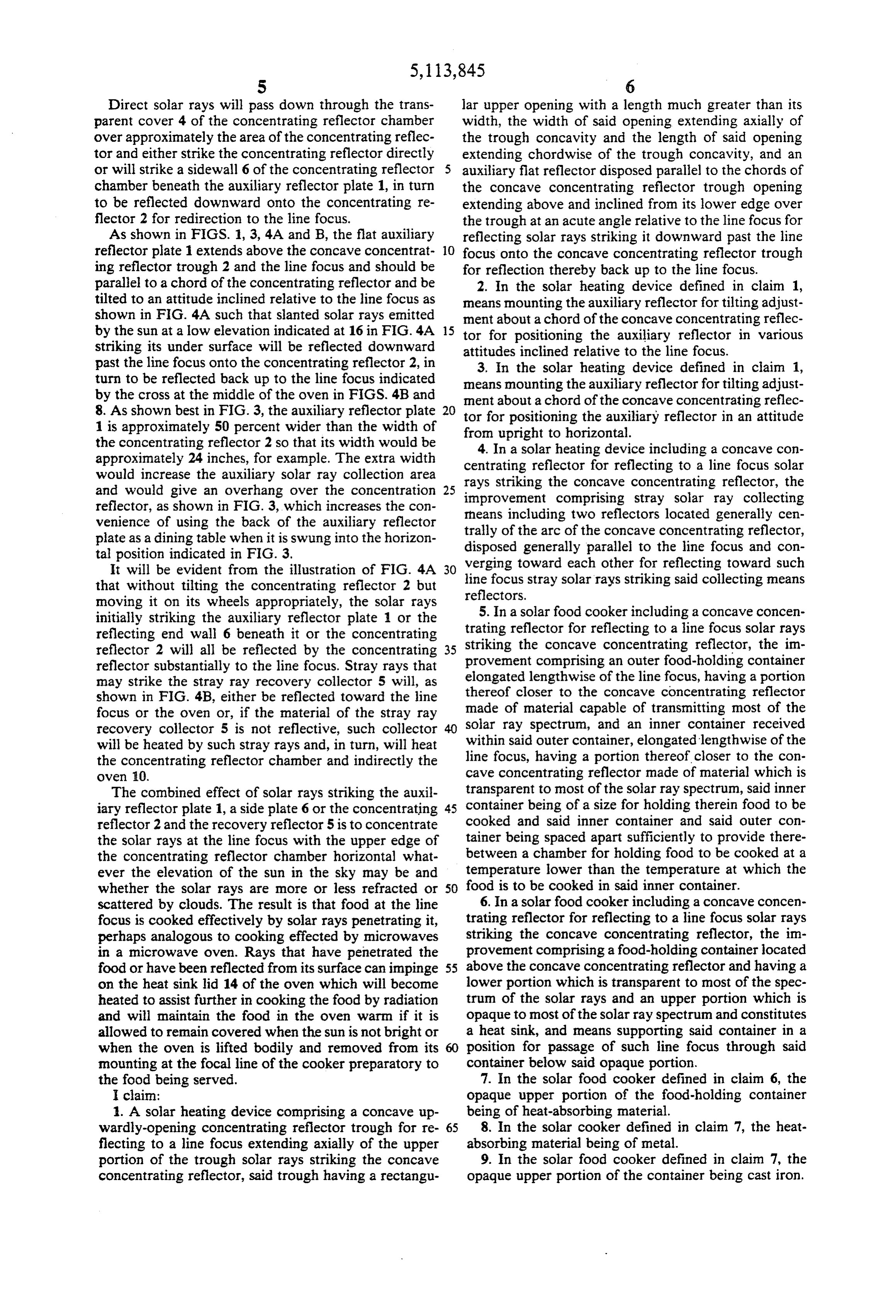
Direct solar rays will pass down through the trans lar upper opening with a length much greater than its parent cover 4 of the concentrating reflector chamber width, the width of said opening extending axially of over approximately the area of the concentrating reflec the trough concavity and the length of said opening tor and either strike the concentrating reflector directly extending chordwise of the trough concavity, and an or will strike a sidewall 6 of the concentrating reflector auxiliary flat reflector disposed parallel to the chords of chamber beneath the auxiliary reflector plate 1, in turn the concave concentrating reflector trough opening to be reflected downward onto the concentrating re extending above and inclined from its lower edge over flector 2 for redirection to the line focus. the trough at an acute angle relative to the line focus for As shown in FIGS. 1, 3, 4A and B, the flat auxiliary reflecting solar rays striking it downward past the line reflector plate 1 extends above the concave concentrat O focus onto the concave concentrating reflector trough ing reflector trough 2 and the line focus and should be for reflection thereby back up to the line focus. parallel to a chord of the concentrating reflector and be 2. In the solar heating device defined in claim 1, tilted to an attitude inclined relative to the line focus as means mounting the auxiliary reflector for tilting adjust shown in FIG. 4A such that slanted solar rays emitted ment about a chord of the concave concentrating reflec by the sun at a low elevation indicated at 16 in FIG. 4A 15 tor for positioning the auxiliary reflector in various striking its under surface will be reflected downward attitudes inclined relative to the line focus. past the line focus onto the concentrating reflector 2, in 3. In the solar heating device defined in claim 1, turn to be reflected back up to the line focus indicated means mounting the auxiliary reflector for tilting adjust by the cross at the middle of the oven in FIGS. 4B and ment about a chord of the concave concentrating reflec 8. As shown best in FIG. 3, the auxiliary reflector plate 20 tor for positioning the auxiliary reflector in an attitude 1 is approximately 50 percent wider than the width of the concentrating reflector 2 so that its width would be from 4.
upright to horizontal.
In a solar heating device including a concave con approximately 24 inches, for example. The extra width centrating would increase the auxiliary solar ray collection area rays strikingreflector for reflecting to a line focus solar and would give an overhang over the concentration improvement comprising concentrating
stray solar reflector, the ray collecting reflector, as shown in FIG. 3, which increases the con rheans including two reflectors located generally cen venience of using the back of the auxiliary reflector trally of the arc of the concave concentrating reflector, plate as a dining table when it is swung into the horizon disposed generally parallel to the line focus and con tal position indicated in FIG. 3.
It will be evident from the illustration of FIG. 4A 30 verging toward each other for reflecting toward such that without tilting the concentrating reflector 2 but line focus stray solar rays striking said collecting means reflectors.
moving it on its wheels appropriately, the solar rays initially striking the auxiliary reflector plate 1 or the 5. In a solar food cooker including a concave concen reflecting end wall 6 beneath it or the concentrating trating reflector for reflecting to a line focus solar rays striking the concave concentrating reflector, the im reflector 2 will all be reflected by the concentrating 35 provement comprising an outer food-holding container reflector substantially to the line focus. Stray rays that elongated lengthwise may strike the stray ray recovery collector 5 will, as of the line focus, having a portion shown in FIG. 4B, either be reflected toward the line thereof closer to the concave concentrating reflector focus or the oven or, if the material of the stray ray made of material capable of transmitting most of the recovery collector 5 is not reflective, such collector solar ray spectrum, and an inner container received will be heated by such stray rays and, in turn, will heat within said outer container, elongated lengthwise of the the concentrating reflector chamber and indirectly the line focus, having a portion thereof closer to the con oven 0. cave concentrating reflector made of material which is The combined effect of solar rays striking the auxil transparent to most of the solar ray spectrum, said inner iary reflector plate 1, a side plate 6 or the concentrating 45 container being of a size for holding therein food to be reflector 2 and the recovery reflector 5 is to concentrate cooked and said inner container and said outer con the solar rays at the line focus with the upper edge of tainer being spaced apart sufficiently to provide there the concentrating reflector chamber horizontal what between a chamber for holding food to be cooked at a ever the elevation of the sun in the sky may be and temperature lower than the temperature at which the whether the solar rays are more or less refracted or 50 food is to be cooked in said inner container. scattered by clouds. The result is that food at the line 6. In a solar food cooker including a concave concen focus is cooked effectively by solar rays penetrating it, trating reflector for reflecting to a line focus solar rays perhaps analogous to cooking effected by microwaves striking the concave concentrating reflector, the im in a microwave oven. Rays that have penetrated the provement comprising a food-holding container located food or have been reflected from its surface can impinge 55 above the concave concentrating reflector and having a on the heat sink lid 14 of the oven which will become lower portion which is transparent to most of the spec heated to assist further in cooking the food by radiation trum of the solar rays and an upper portion which is and will maintain the food in the oven warm if it is opaque to most of the solar ray spectrum and constitutes allowed to remain covered when the sun is not bright or a heat sink, and means supporting said container in a when the oven is lifted bodily and removed from its position for passage of such line focus through said mounting at the focal line of the cooker preparatory to container below said opaque portion.
the food being served. 7. In the solar food cooker defined in claim 6, the clain: opaque upper portion of the food-holding container 1. A solar heating device comprising a concave up being of heat-absorbing material.
wardly-opening concentrating reflector trough for re 65 8. In the solar cooker defined in claim 7, the heat flecting to a line focus extending axially of the upper absorbing material being of metal.
portion of the trough solar rays striking the concave 9. In the solar food cooker defined in claim 7, the concentrating reflector, said trough having a rectangu opaque upper portion of the container being cast iron.
Page 11
10. In the solar food cooker defined in claim 6, the chord of the concave concentrating reflector for posi opaque portion of the container being a heat-absorbing tioning said auxiliary flat reflector plate in an attitude metal lid. inclined at an acute angle relative to the line focus up 11. In a solar food cooker including a concave con ward from said chord of said concentrating reflector centrating reflector for reflecting to a line focus solar and over said concentrating reflector for reflecting rays striking the concave concentrating reflector, the solar rays striking said auxiliary flat reflector plate improvement comprising a food-holding container for downward onto the concave concentrating reflector. holding food substantially at such line focus, and a heat 13. A process for utilizing solar energy including absorbing lid covering the upper portion of said food concentrating solar rays reviewed through the upper holding container and located above the line focus to be O heated by residual solar rays reflected from or passing aopening of a concave concentrating reflector trough to through or close to food held by said food-holding such trough,extending line focus the axially of the upper portion of improvement comprising collecting container.
12. In a solar heating device including a concave solar rays over an area in addition to the area of the concentrating reflector for reflecting to a line focus 15 concave concentrating reflector trough upper opening, solar rays striking the concave concentrating reflector, extending upward above a chord of such trough and the improvement comprising reflecting sides of gener inclined from its lower edge over such trough, and ally segment shape closing opposite sides of the concave reflecting solar rays collected in such additional area concentrating reflector, an auxiliary flat reflector plate downward past the line focus onto the concave concen mounted above one of said sides alongside the concave 20 trating reflector trough for reflection thereby upward concentrating reflector, and means mounting said auxil to the line focus. is k h is iary flat reflector plate for tilting adjustment about a
Page 12
UNITED STATES PATENT AND TRADEMARK OFFICE
CERTIFICATE OF CORRECTION
NVENTOR(S) : Martin E. Nix
It is Certified that error appears in the above-identified patent and that said Letters Patent is hereby COrrected as shown below:
Claim l3: Column 8, line 9, cancel "reviewed" and insert --received--.
Signed and Sealed this
Seventeenth Day of May, 1994
(a teen
BRUCE LEHMAN
Attesting Officer Commissioner of Patents and Trademarks
Provenance
- Collection
- Cited prior art
- Original PDF
- patentimages.storage.googleapis.com →
- Filed
- 1990-09-20
- Pages
- 12
- Method
- pdftotext (the PDF's own text layer) + pdftoppm 300dpi page scans
- Source
- Google Patents bibliographic record
- Granted
- 1992-05-19
- Inventors
- Martin E. Nix
- Transcribed from
- patentimages.storage.googleapis.com →