patent · US6178707
Small skylight with non-tracking solar collector
30 January 2001
Page 1 — bibliographic record
(12) United States Patent (10) Patent No.: US 6,178,707 B1 Bengtson (45) Date of Patent: Jan. 30, 2001
(54) SMALL SKYLIGHT WITH NON-TRACKING 4,561,424 12/1985 Gill et al.. SOLAR COLLECTOR 4.575,196 3/1986 Clegg.
(76) Inventor: Daniel Emilio Bengtson, Estanislao 4,720,170 1/1988 Learn, Jr. ............................. 359/597 Diaz 455-San Isidro-Peia de, Buenos 4,883,340 11/1989 Dominguez.
Aires (AR) 5,099,622 3/1992 Sutton.
(*) Notice: Under 35 U.S.C. 154(b), the term of this 5,467,564 11/1995 DeKeyser et al.. patent shall be extended for 0 days. 5,493.824 2/1996 Webster et al. .
(21) Appl. No.: 09/193,137 5,578,140 11/1996 Yogev et al. .
(22) Filed: Nov. 17, 1998 5,655,339 8/1997 DeBlock et al. . 5,878,539 3/1999 Grubb .................................... 52/200 (30) Foreign Application Priority Data 5,896,712 * 4/1999 Chao ................ ... 52/200 Aug. 13, 1998 (AR) .......................................... P98-0104.012 5,983,581 * 11/1999 De Block et al. ..................... 52/200 (51) Int. Cl." ..................................................... E04D 13/03 * cited by examiner (52) U.S. Cl. ............................................... 52/200; 359/597 Primary Examiner Michael Safavi (58) Field of Search ................................... 52/173.3, 200; (74) Attorney, Agent, or Firm-Robert E. Bushnell, Esq. 359/591,592, 595,597,598 (57) ABSTRACT (56) References Cited A new Small Skylight which can be installed in buildings in
advantage of this skylight over previous ones lies in its Small 668,404 2/1901 Hanneborg ........................... 359/597 size, thus avoiding having to make a wide roof opening for 1,254,520 1/1918 Macouff ............................... 359/595 installation, with the consequent risks and dangers involved. 3,899,672 8/1975 Levi-Setti. An external reflecting flat sheet rotating with respect to a
3,923,381 12/1975 Winston. transverse axis placed on the top base of a vertical light 3,964,464 6/1976 Hockman. conduit tube. The tube intercalated by a jacket tube, goes 4,003,638 1/1977 Winston. through the roof. The external reflecting sheet Sends the 4,131,485 12/1978 Meinel et al.. collected light beams to a mirror, which is tilted on the 4,201,197 5/1980 Dismer. Vertical tube, the interior Surface of the tube being capable 4,222,370 9/1980 DeGeus. of receiving and Sending towards the interior of the room he 4,246,477 1/1981 Latter ................................... 359/595 reflected light beams received from said mirror. Another 4,306,769 12/1981 Martinet. embodiment allows the user to regulate the external reflector
4,349.245 9/1982 Kliman. operative tilting, as well as to rotate respect to a vertical axis to achieve for the best orientation relative to the Sun.
4,541,414 9/1985 Mori. 17 Claims, 6 Drawing Sheets
Page 2
Drawing sheet — no readable text.
Page 3
Drawing sheet — no readable text.
Page 4
Drawing sheet — no readable text.
Page 5
Drawing sheet — no readable text.
Page 6
Drawing sheet — no readable text.
Page 7
Drawing sheet — no readable text.
Page 8
SMALL SKYLIGHT WITH NON-TRACKING reflectors for concentration. Other approaches are seen in SOLAR COLLECTOR U.S. Pat. Nos. 5,374,317, to Lamb et al., entitled Multiple Reflector Concentrator Solar Electrical Power System and
CLAIM OF PRIORITY 5,578,140, to Yogev et al., entitled Solar Energy Plant, This application makes reference to, incorporates the describe multiple reflector systems. U.S. Pat. No. 5,062,899, to Kreuer, entitled Wide Acceptance Angle, High Concen
Same herein, and claims all benefits accruing under 35 tration Ratio Optical Collector, describes a Cassegrain U.S.C. S.119 from an application for SMALL SKYLIGHT collection System. None of these patents, however, Specifi WITH NON-TRACKING SOLAR COLLECTOR earlier cally describes a device designed to transmit the collected filed in the Argentina National Institute of Industrial Prop light to a room for lighting.
erty on Aug. 3, 1998 and there duly assigned Serial No. A number of patents do describe the collection of Sunlight
to provide room lighting. Some of these involve the use of
BACKGROUND OF THE INVENTION transparent domes or Skylights on the roof. Examples include U.S. Pat. No. 4,329,021, to Bennet et al., entitled 1. Technical Field 15 Passive Solar Lighting System, U.S. Pat. No. 4,349.245, to This invention pertains to the class of devices for the Kliman, entitled Modular Natural Lighting System, U.S. Pat. collection and utilization of Solar energy and, more No. 4,883,340, to Dominguez, entitled Solar Lighting particularly, to devices utilizing Solar energy for interior Reflector Apparatus Having Slatted Mirrors And Improved lighting. Tracker, U.S. Pat. No. 5,099,622, to Sutton, entitled 2. Related Art Skylight, U.S. Pat. No. 5,467,564 to DeKeyser et al., entitled Due to lack of Space, in the design or renovations per Daylight Collection And Distribution System, U.S. Pat. No. formed to a building many rooms or parts of houses, sheds, 5,493.824 to Webster et al., entitled Rotatably Mounted offices, Storerooms, and the like, are left without much Skylight Having Reflectors, U.S. Pat. No. 5,648,873, to natural light. This situation causes the immediate need to 25 Jaster et al., entitled Passive Solar Collector, and U.S. Pat. resort to electrical lighting, with the consequent cost No. 5,655,339, to DeBlock et al., entitled Tubular Skylight With Improved Dome. However, in all of these patents, only incurred due to electrical consumption. the Sunlight impinging on an area essentially equal to that of Whenever possible, alternative lighting by means of sky lights which are preferably placed on an already existing the skylight roof hole is transmitted. That is, there is no concentration and use of Sunlight falling away from the roof should be considered. Currently available skylights, aperture in the roof. Thus, to bring in reasonable amounts of however, Show Some deficiencies. One problem is that Sunlight may require quite large roof apertures. making a large opening in the roof where the Skylight is A number of U.S. patents do describe interior lighting going to be placed is invariably necessary. Making this hole using is usually difficult and expensive, particularly when the roof wider means area of collecting and concentrating Sunlight from a than the skylight access hole through the roof.
is a reinforced concrete slab. The larger the hole, the more 35 For example, U.S. Pat. No. 4,201,197, to Dismer, entitled difficult and expensive this is. Solar Energy Collector Having A Fiber-Optic Cable, uses a A Second problem with large holes is that of break-ins parabaloidal mirror and a Smaller mirror to focus light onto through the Skylight. In order to avoid a break-in, these fiber-optics. This device involves a parabolic dish which openings require, besides the sky-light itself, the installation must be motorized to track the Sun, however. U.S. Pat. No. of bars to impede the access to the interior, thus increasing 40 4,306,769, to Martinet, entitled Interior Illumination Appa the installation cost. This can also be an esthetic problem. ratuS Using Sunlight, describes a trumpet-shaped light pipe Another problem is that of rain leakage where the Skylight with a Secondary reflector. This apparatus, however, requires meets the roof. The bigger the opening, the greater the risk Vertical Support of the collection trumpet on top of the light of rain leakage. Yet another problem is that most of the pipe, probably increasing the weight and limiting the size of existing Skylights are not very decorative. Most of them do 45 the trumpet collector. U.S. Pat. No. 4,411,490, to Daniel, not correspond with the rooms interior design criteria and entitled Apparatus for Collecting, Distributing and Utilizing are not easily adapted to do So. Solar Radiation, involves a complex array of Solar gathering A number of U.S. patents address aspects of Solar energy cells, which are probably expensive and difficult to install. collection. For example, the following U.S. patents describe U.S. Pat. No. 4,475,536, to Dame, entitled Solar Collector devices for the concentration of Solar energy generally for 50 Skylight ASSembly, describes a complex arrangement of Solar heating purposes but do not describe use for interior parabolic reflectors. Its design is complex and undoubtedly lighting. U.S. Pat. No. 3,899,672, to Levi-Setti, entitled expensive, resulting from its dual function as a Solar heater. Solar Energy Collection, U.S. Pat. No. 3,923,381 to Winston U.S. Pat. No. 4,514,414, to Mori, entitled Apparatus for entitled Radiant Energy Collection, U.S. Pat. No. 4,003,638 Collecting Sunlight, describes a tall, roughly conical reflec to Winston, entitled Radiant Energy Collection and U.S. Pat. 55 tor. This System is actually designed to collect diffuse rather No. 4,131,485 to Meinel et al., entitled Solar Energy Col than direct Sunlight, and the device has a fairly large mass lector and Concentrator all describe conical or trough compared to its light collection area, both factors probably shaped Solar collection devices for Solar heating. Other limiting the amount of light usefully transmitted to the patents describing the use of parabolic or curved mirrors to interior. U.S. Pat. No. 4,575,196, to Clegg, entitled Conical concentrate solar energy include U.S. Pat. No. 3,964,464 to 60 Beam Concentrator, is a device consisting of a vertical Hockman, entitled Solar Radiation Collector and Series of lenses. Such a device is undoubtedly expensive and Concentrator, U.S. Pat. No. 4,222,370, to DeGeus, entitled may have weight limitations on its size. U.S. Pat. No. Nontracking Concentrating Solar Collector, and U.S. Pat. 5,540,216, to Rasmusson, entitled Apparatus And Method No. 4,561,424, to Gill et al., entitled Nontracking Parabolic for Concentrating Radiant Energy Emanated By A Moving Solar Energy Collecting Apparatus. U.S. Pat. Nos. 3,902, 65 Energy Source, involves a Static collector using two facing 794, to Abrams, entitled Fresnell Lens, and 4,612,913, to concave reflectors, the Second reflector including Small Mori, entitled Solar Energy Collector Array, use Fresnel conveX Surfaces, which divert the beams towards an objec
Page 9
tive. The complexity of the surfaces of this device probably greater than with any skylight known in the art, with the makes it expensive to manufacture. Thus the devices Same diameter or Section. Therefore, according to the described in the above patents probably suffer from prob present invention, better natural lighting results can be lems of expense, limited light transmission, or difficulty of obtained, with a minimum roof opening installation, having installation. 5 no need for closing bars. The Skylight of the present inven Based on my observation of the art, I have discovered that tion is extremely simple and consequently rain leakproof what is needed is an improved skylight with a narrow light and its shape is easily adaptable to the decorative design of conduit penetrating the roof which nonetheless provides a the room to be lighted.
high transmission of light from the outside to the inside of BRIEF DESCRIPTION OF THE DRAWINGS the building. Such a skylight, which concentrates Sunlight but requires only a Small aperture in the roof, can Solve the The advantages herein briefly described will be more fully problems addressed earlier, including minimizing the Size of understood, and further advantages will become apparent to the hole which must be made to the roof, lowering the users and those skilled in the art. In order to facilitate the installation cost, avoiding the hazard of break-ins, and understanding of the constructive, constitutive and func improving room esthetics. 15 tional characteristics of the Skylight of the present invention,
SUMMARY OF THE INVENTION a preferred embodiment is hereinafter described, which is Schematically illustrated-with no specific Scale-in the
It is therefore, an object of the present invention to enclosed figures. It should be apparent that the following is provide an improved Skylight for a building. only an example and should not be considered as restrictive It is another object to provide a skylight with improved or exclusive to the Scope of the present invention. efficiency of light transmission to the interior of the building. Consequently, the following example is intended for It is still another object to provide a Skylight requiring explanatory and illustrative purposes of the idea in which the only a narrow hole in the roof of the building where it is present invention is based on.
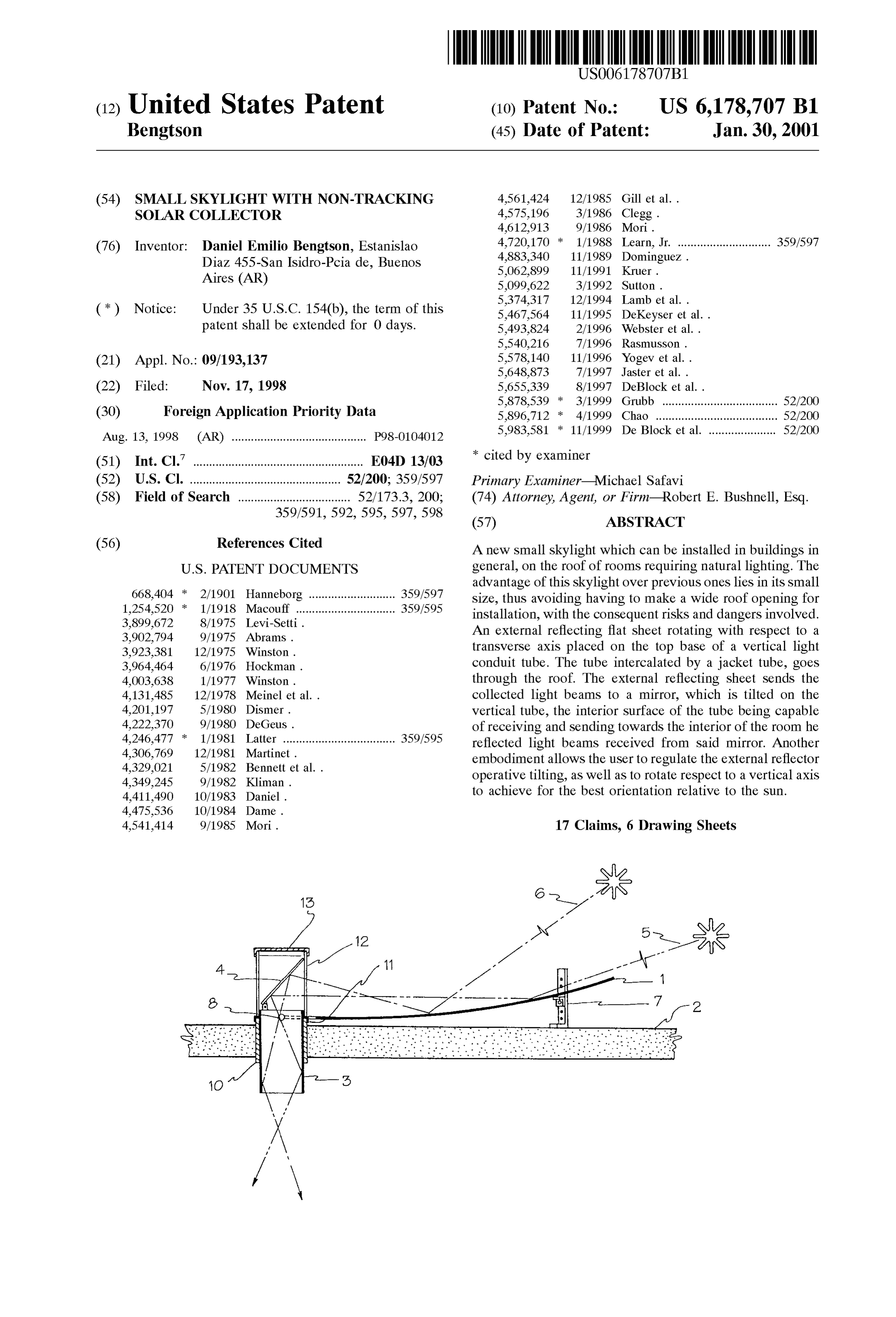
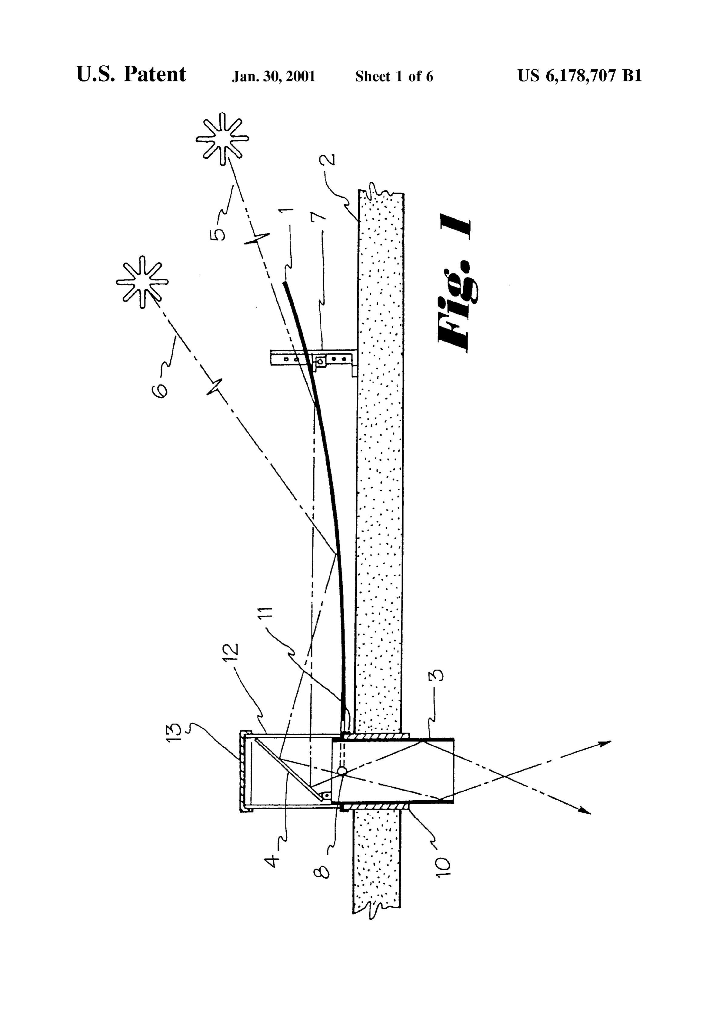
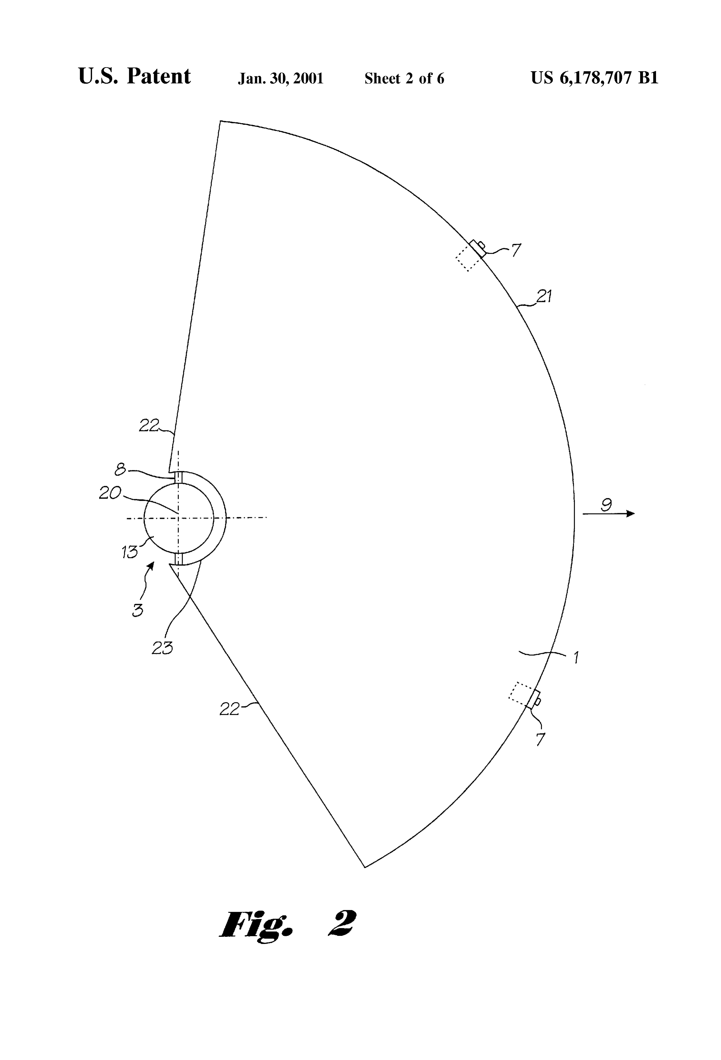
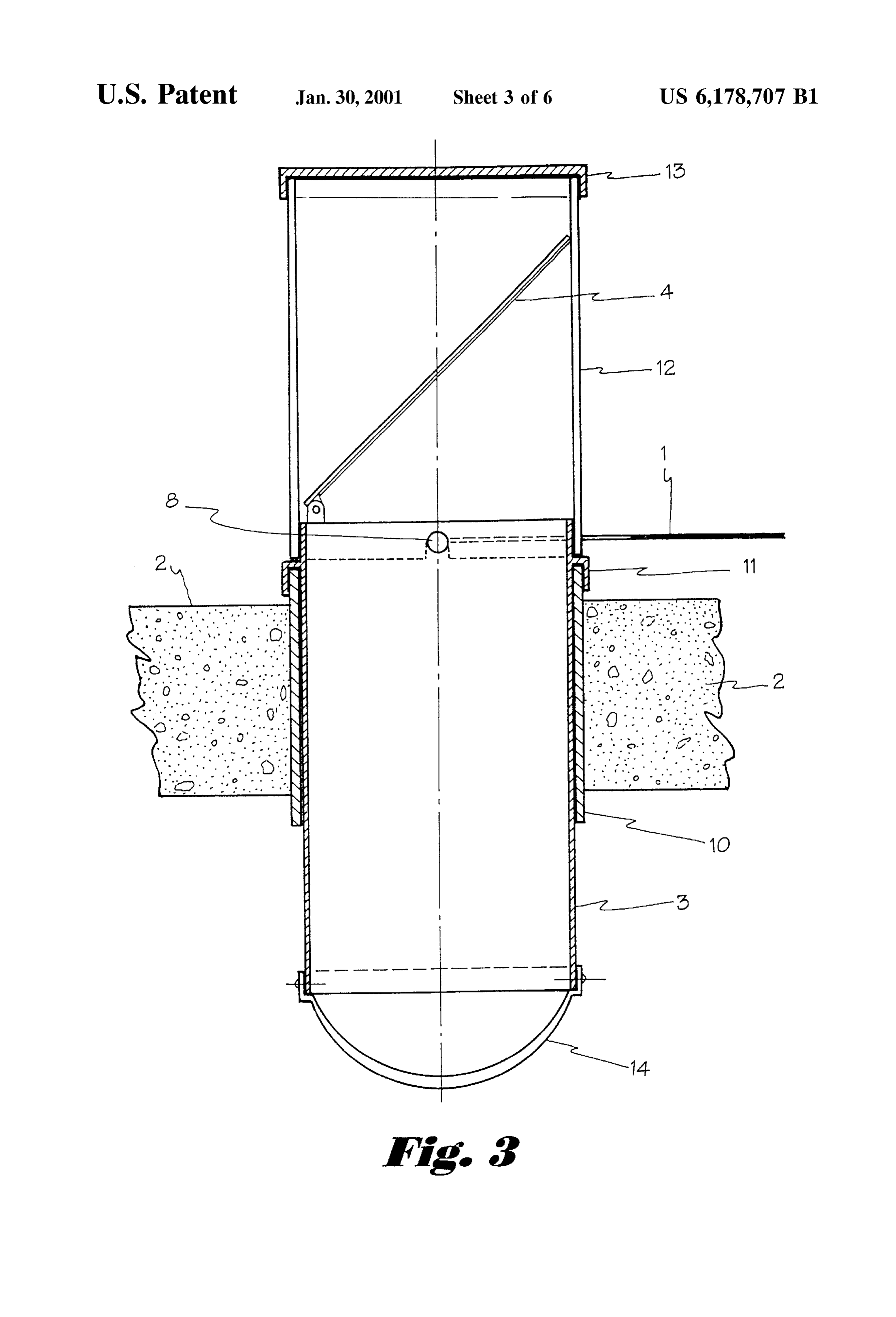
installed. FIG. 1 is a vertical cross-section illustrating the Skylight It is yet another object to provide a Skylight offering 25 assembly placed on a roof formed by a slab, shown Sche improved ease of installation. matically in order to make its functioning principle explicit. It is a further object to provide a Skylight allowing FIG. 2 is a top plan view illustrating an external reflector, inexpensive installation. a sheet collecting and reflecting Solar beams. It is a still further object to provide a skylight offering FIG. 3 is a vertical cross section blown up detail illus improved resistance to break-in, through the Skylight, of the trating a preferred embodiment of the light conduit installed building where the skylight is located.
It is a yet further object to provide a skylight offering of a room. in order to provide natural lighting to the interior in the roof improved resistance to roof leakage where the skylight is FIG. 4 is also a vertical croSS Section illustrating a installed.
35 constructive variation of the light conduit installed in the
It is a still yet further object to provide a skylight which roof of the room to be lighted.
is esthetic and decorative.
It is also an object to provide a skylight which is adaptable FIG. 5 is also a vertical croSS Section illustrating another to the decor of the room which is located. constructive variation of the light conduit installed in the It is an additional object to provide a Skylight which 40 roof of the room to be lighted.
requires no motor and only minimal adjustment to track the FIG. 6 is a plan view, similar to FIG. 2, illustrating a SU. constructive variation of the external reflector assembly. These objects are effectively met with the small skylight FIG. 7 is a vertical cross section of an embodiment of the described in the present invention, Since this skylight uses a mounted inillustrating invention a slab roof.
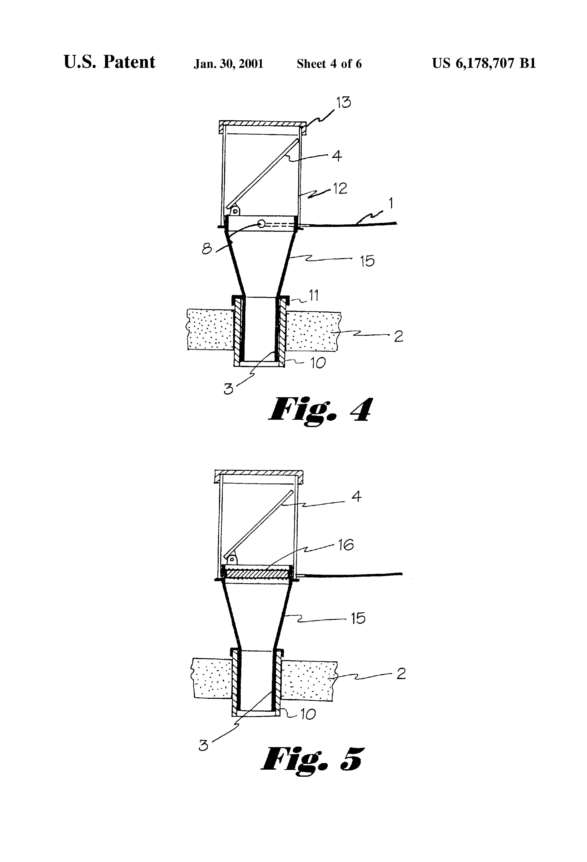
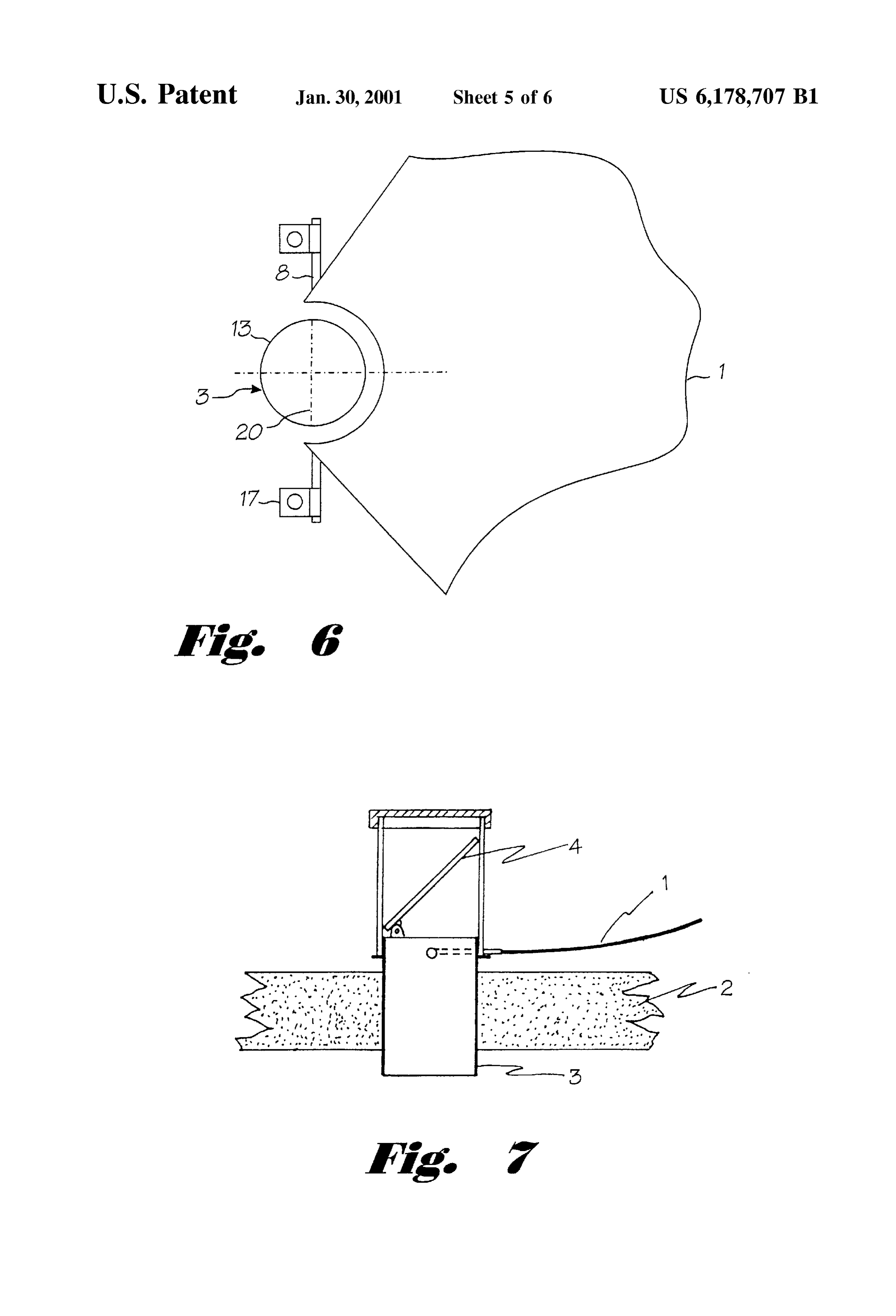
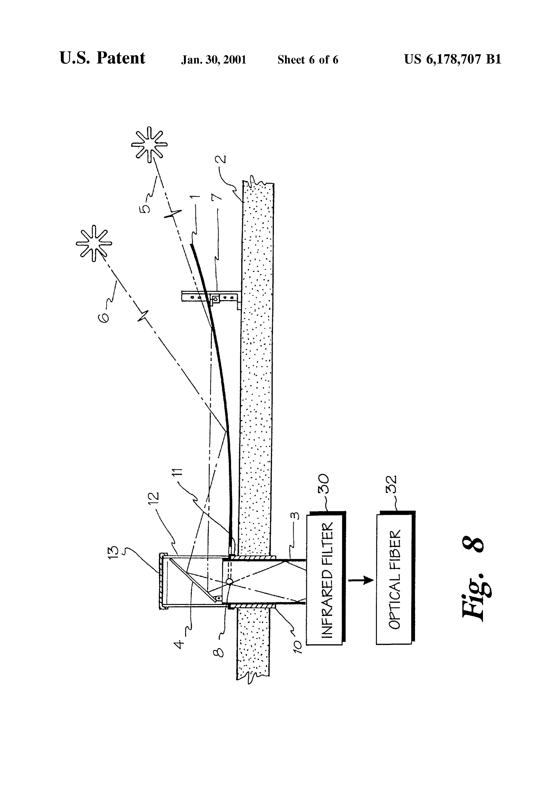
a variation in the light conduit tubular body of Small diameter or Section placed through the 45 roof thickness, incorporating a capturing means for exterior FIG. 8 is a schematic view of another embodiment of the Sunlight and reflecting it towards this tube in order to be invention.
transmitted to the rooms interior. The present invention is a All reference numbers in the figures correspond to the Small Skylight composed of a light conduit or tube slightly Same or equivalent parts or constitutive elements of the taller than the thickness of the roof in which it will be 50 device, according to the example chosen for the illustration installed. This light conduit or tube is placed in a vertical of the Skylight of the present invention. position, and has open ends, or bases, its internal Surface DETAILED DESCRIPTION OF THE DRAWINGS being preferably polished or showing great light-reflecting capacity. A mirror plate is placed in correspondence to the As can be seen in FIG. 1, the skylight of the present Superior-exterior base, provided in an oblique position, 55 invention is based on the use of external reflector 1. This facing the interior of the tube. A wide external reflecting reflector can be flat or slightly concave upward, having a sheet completes the device, this sheet projecting above the general structure Such as a Sector of a circle (see FIG. 2), and roofs external Surface in a slightly tilted position relative to can be constructed of different materials among which a the horizontal plane, Such that the Surface rises as it with Stainless Steel or aluminum polished sheet is preferred. draws from the tube. The reflecting sheet or external reflec 60 Reflecting plate 1 has a round opening where spindles 8 are tor collects Solar beams and sends them to the obliquely attached, and reflecting plate 1 is Supported by and tilts on positioned mirror, this mirror reflecting the beams towards Spindles 8 and also rests on vertical Supports 7, maintaining the interior of the Small tube, Substantially increasing the reflecting plate 1 in a slightly elevated position over the roof. lighting capacity transmitted towards the interior of the More Specifically, reflecting plate 1, as shown in FIG. 2, has OO. 65 outer edge 21 corresponding to a portion of the circumfer The embodiments of the invention demonstrate that the ence of an outer circle, Side edges 22 lying along radii of the improvement of the natural light transmission capacity is outer circle, and inner edge 23, defining a Substantially
Page 10
S 6
Semicircular opening offset slightly inward from the center In this respect, in FIG. 2 the format chosen for external of the Outer circle. Attached to inner edge 23 are two reflector 1 can be seen to be a circular Section having about spindles 8, defining axis 20 around which external reflector 120 amplitude, thus covering most of the Sun's course in 1 may be slightly tilted. External reflector 1 is further the sky during the day. Arrow 9 in FIG. 2, shows how this mounted on vertical Supports 7, maintaining it slightly above device should be oriented. Arrow 9 is roughly parallel to the the roof. Peripherally placed vertical supports 7 have an meridian where the device is, and points toward the equator, adjustable height in order to allow the user to determine the i.e., approximately to the North in the Southern hemisphere tilting degree appropriate to the Sun's position in the current and to the South in the Northern hemisphere.
SCSO.
Light conduit, or tube, 3 goes through roof 2 above the If, for example, more lighting is preferred during the room to be lighted, and allows the natural light to pass morning, the only requirements will be to rotate the device towards the interior of Said room. Light conduit, or tube, 3 skylight thusrising towards the of the Sun. It should be noted that said constituted will also work with small light can be made from a metal Such as StainleSS Steel or aluminum, having its internal Surface duly treated to facili amounts,atmospheric even in the shade, Since Said Skylight collects tate Sunlight reflection. Mirror 4 is placed above light 15 diffuse light. This is to say that the Skylight is conduit 3, mirror 4 being a prism or a reflecting Surface. The reflected on Small collecting also prepared for and transmitting Sunlight
Suspended dust particles or vapor.
function of mirror 4 is to divert downwards the light coming Consequently, the invented from external reflector 1; this arrangement is Similar to the both at Sunrise as well as atdevice provides a light lighting Sunset, even if not receiving top part of a periscope. direct Sunlight or on a cloudy day. In one embodiment of the invention, seen in FIG. 3, light FIG. 3 specifically shows that this skylight rotates with conduit 3 includes on its upper Section, rib projection 11, respect to jacket tube 10, Since light conduit 3 lies on Said which rests on jacket tube 10, jacket tube 10 being mounted jacket tube by means of the rib projection 11, also avoiding in roof 2. On rib projection 11 is transparent cowl 12. Lid 13, on top of transparent cowl 12, functions to close the assem rain entrance. FIG.3 shows external reflector 1 supported by bly in order to avoid any unwanted rain or dust entrance. The 25 spindles 8, on which it can be rotated about axis 20 when axis 8 lies on properly defined openings corresponding to the ever regulating the vertical incidence angle is required. Superior circumferential border of light conduit 3 also going Transparent cowl 12 can be a glass tube or any other through Second openings performed on Said cowl inferior transparent material impeding mirror 4 from dirtying. The border 12. Sealing means known in the art will produce the top closing of the assembly is provided by lid 13. tight closure of the assembly, it being Still possible for the Another embodiment of this invention provides transpar user to rotate light conduit 3 together with transparent cowl ent cover 14 on the bottom of light conduit 3, inside the 12 and external reflector 1 Supported by transparent cowl 12, room. Transparent cover 14 may be dome-shaped or of and thus track the assembly towards a more effective func Similar shape, the function of transparent cover 14 being to tioning position. disperse or diffuse the radiated light at a greater angle in One of the problems posed by the desire to take advantage 35 order to produce a more uniform lighting. of Solar energy is following this Sun. Motorized tracking Another embodiment covered by the scope of this inven devices are too complex and consequently expensive as a tion is that shown by FIG. 4, where mirror 4 is wider than means for following the Sun's Seasonal and diurnal move the diameter of light conduit 3. In this case, light conduit 3 ment. The present invention obviates motorized tracking. AS is modified to include conical connector 15, having the can be seen in FIGS. 1 and 2, in the present invention, 40 shape of a truncated cone and whose interior Surface is also Sunlight collection is achieved through external reflector 1 capable of reflecting light. This Solution is useful for cases which has a very wide acceptance range for the light when the user wishes to have a very Small roof opening. incidence angle. This is a very simple Solution, lacking any Another embodiment, also having conical connector 15, is moving parts, and only requiring minor Seasonal adjust shown in FIG. 5. In this embodiment, lens 16, which can be ments if the user desires an optimum functioning. 45 a “Fresnel” lens or another optical concentration means to Most Solar energy collectors known in the art require Solar concentrate light in light conduit 3, is included in the lower energy concentration, using concave mirrors, or very Special interior portion of transparent cowl 12 or the upper region of optical Systems. Such as “cassegrain', generally concentrat conical connector 15.
ing light in one focus. AS can be seen in the case of low angle In yet another embodiment, shown in FIG. 6, external incident radiation 5 and high angle incident radiation 6, the 50 reflector 1 is mounted independent from the body of light present invention uses external reflector 1, collecting inci conduit 3, in Such a way that light conduit 3 can rotate dent sunlight and reflecting it toward mirror 4. FIG. 1 shows independently without pulling along external reflector 1, In that when low angle incident radiation 5 is sent by external this embodiment, the user can rotate light conduit 3 from the reflector 1 towards mirror 4 and then towards the interior of interior of the room and can thereby regulate the light light conduit 3, whose internal Surface is duly treated as has 55 intensity to a desired level during the day. In this case, been previously mentioned, the light beams exit is tracked spindles 8 on which the reflector is installed, are fastened to towards the interior of the room. the roof by means of supports 17. In a different Season, when the Sun appears at a greatest It should be noted that light conduit 3 may have any height on the horizon, high angle incident radiation 6 is horizontal cross-section. In an additional embodiment, light similarly collected by external reflector 1, and no further 60 conduit 3 can also be stationary, as shown in FIG. 7, where adjustment is required. However, the present invention also jacket tube 10 is not used. In another embodiment shown provides an improvement in the functional efficiency of schematically in FIG. 8, this device can be also applied to external reflector 1, by adjusting the Sun incidence angle a illuminate optical fibre 32, in which case infrared filters 30 few times a year, changing the height of the Supporting rib will be needed in order to keep the temperature low. of Said adjustable height Support 7 since Said rib can rotate 65 Generally, the device of the present invention can be used on Spindles 8 around axis 20 changing the tilting angle of as a wide acceptance angle collector for any kind of radiant external reflector 1. energy. Having thus described the invention in rather full
Page 11
detail, it will be readily apparent to a perSon of ordinary skill axis pointing away from the center of Said Semicircle that various changes and modifications can be made without and extending past Said Side edges of Said external departing from the Spirit of the invention. All of Such reflector;
changes and modifications are contemplated as being within a plurality of Supports affixed to the roof, said Supports the Scope of the present invention as defined by the Sub retaining Said two spindles, and joined claims. a vertical Support affixed to Said roof and adjustably What is claimed is:
1. A Skylight mounted through the roof of a building, mounted to Said back edge of Said external reflector. comprising: 9. The skylight of claim 1, further comprised of: a light conduit mounted Vertically through an aperture in Said light conduit being mounted rotatably about its the roof, Said light conduit being essentially cylindrical, cylindrical axis.
Said light conduit having an inside Surface which 10. The skylight of claim 1, further comprised of: reflects light and Said light conduit having a top open a jacket tube, mounted in Said aperture in the roof, Said ing and a bottom opening; jacket tube Surrounding Said light conduit; a transparent cowl, Said transparent cowl being essentially 15 Said light conduit being rotatable about its cylindrical axis cylindrical and Said transparent cowl being mounted within Said jacket tube.
coaxially with and on the top opening of Said light 11. The skylight of claim 1, further comprised of a conduit; transparent cover mounted on the bottom opening of Said a lid mounted on Said transparent cowl; light conduit.
12. The skylight of claim 1, further comprised of:
a mirror mounted obliquely downward inside Said trans Said transparent cowl having a diameter greater than that parent cowl, and of Said light conduit;
an external reflector mounted to the roof near the aperture a conical connector installed between Said transparent in the roof and generally toward the earth's equator, So cowl and Said light conduit; as to reflect Sunlight toward Said mirror. 25 2. The Skylight of claim 1, further comprising Said exter Said conical connector having the general shape of a nal reflector having a flat Surface. hollow truncated cone having a narrow end of diameter 3. The Skylight of claim 1, further comprising Said exter Similar to that of Said light conduit and a wide end of nal reflector having a Surface which is curved concave diameter Similar to that of Said transparent cowl; upward. Said narrow end of Said conical connector being attached 4. The Skylight of claim 1, further comprising: to Said top end of Said light conduit and Said transparent Said external reflector being shaped approximately as a cowl being attached to Said wide end of Said conical Sector of an outer circle, Said external reflector having connector; and two Side edges which lie along two radii of Said outer Said conical connector having a light-reflective inside circle, a back edge which is a portion of the circum 35 Surface.
ference of Said outer circle, and a front edge which is 13. The skylight of claim 12, further comprising: approximately a Semicircle of diameter slightly larger a lens mounted inside Said wide end of Said conical than the outside diameter of Said light conduit, Said COnnectOr.
center of Said front edge being offset slightly toward 14. The skylight of claim 1, further comprising: Said back edge from the center of Said outer circle, 40 means for filtering infrared light from the light passing Said external reflector being positioned So that the center down the light conduit; and of Said Semicircle approximately corresponds to the optical fibers connected at the bottom of Said light conduit center of Said top of Said light conduit; and to further conduct the light.
Said external reflector being oriented So that the direction 45 15. The skylight of claim 1, further comprising said bisecting Said two radii points roughly along the North external reflector being made of Stainless Steel or aluminum. South meridian toward the earth's equator. 16. The skylight of claim 1, further comprising said mirror 5. The skylight of claim 4, further comprised of said two being a prism which reflects light.
Side edges of Said external reflector defining an angle of 17. A skylight mounted through the roof of a building, approximately 120 degrees. comprising:
6. The skylight of claim 4, further comprised of: 50 a light conduit mounted vertically through an aperture in
Said external reflector being tiltably mounted around an the roof, Said light conduit being polygonal in croSS axis oriented horizontally and approximately East Section, Said light conduit having an inside Surface West, Said axis passing roughly through the center of which reflects light and Said light conduit having a top Said Semicircle.
opening and a bottom opening, 7. The skylight of claim 6, further comprised of: a transparent cowl, Said transparent cowl being essentially Said external reflector further comprising two Spindles cylindrical and Said transparent cowl being mounted affixed to Said external reflector and oriented along Said coaxially with and on the top opening of Said light axis pointing toward the center of Said Semicircle and conduit;
extending past Said front edge of Said external reflector; 60 a lid mounted on Said transparent cowl; Said two Spindles being adjustably attached to Said light a mirror mounted obliquely downward inside Said trans conduit; and parent cowl, and a vertical Support affixed to Said roof and adjustably an external reflector mounted on the roof near the aperture mounted to Said back edge of Said external reflector. in the roof and generally toward the earth's equator, So 8. The skylight of claim 6, further comprised of: 65 as to reflect Sunlight toward Said mirror. Said external reflector further comprising two Spindles affixed to Said external reflector and oriented along Said k k k k k
Provenance
- Collection
- Cited prior art
- Original PDF
- patentimages.storage.googleapis.com →
- Filed
- 1998-11-17
- Pages
- 11
- Method
- pdftotext (the PDF's own text layer) + pdftoppm 300dpi page scans
- Source
- Google Patents bibliographic record
- Granted
- 2001-01-30
- Inventors
- Daniel Emilio Bengtson
- Transcribed from
- patentimages.storage.googleapis.com →