patent · US5058675
Method and apparatus for the destructive distillation of kerogen in situ
22 October 1991
Page 1 — bibliographic record
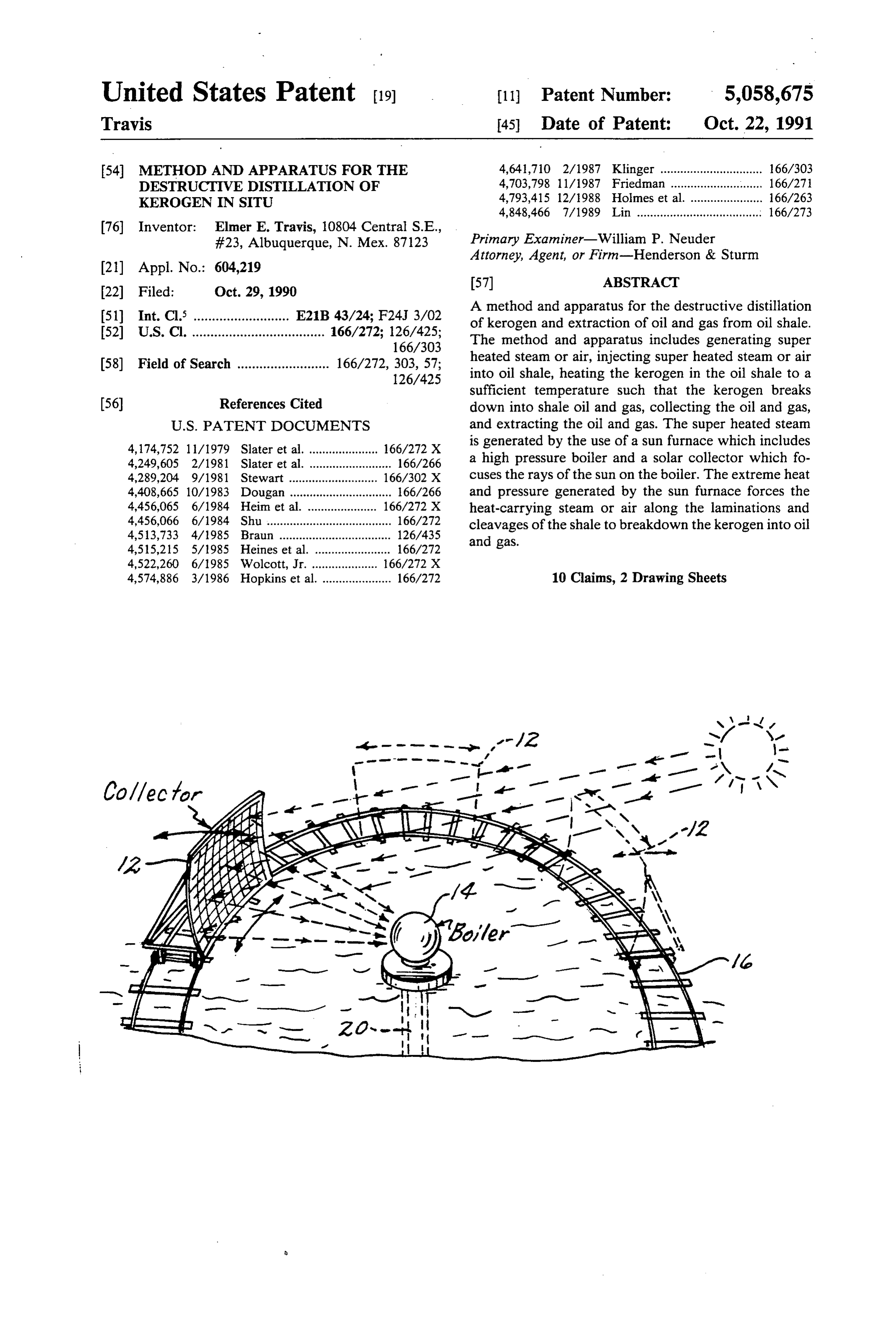
United States Patent (19) 11 Patent Number: 5,058,675 Travis 45 Date of Patent: Oct. 22, 1991 54 METHOD AND APPARATUS FOR THE 4,641,710 2/1987 Klinger ............................... 166/303 DESTRUCTIVE DISTILLATION OF 4,703,798 11/1987 Friedman ......... ... 166/27 KEROGEN IN STU 4,793,415 12/1988 Holmes et al. ... 166/263 4,848,466 7/1989 Lin ...................................... 166/273 (76) Inventor: Elmer E. Travis, 10804 Central S.E., #23, Albuquerque, N. Mex. 87123 Primary Examiner-William P. Neuder
Attorney, Agent, or Firm-Henderson & Sturm
(51) Int. Cl. .......................... E21B 43/24; F24J 3/02 A method and apparatus for the destructive distillation 52) U.S. Cl. .................................... 166/272; 126/425; of kerogen and extraction of oil and gas from oil shale. 166/303 The method and apparatus includes generating super 58) Field of Search ......................... 166/272,303, 57; heated steam or air, injecting super heated steam or air 126/425 into oil shale, heating the kerogen in the oil shale to a sufficient temperature such that the kerogen breaks (56) References Cited down into shale oil and gas, collecting the oil and gas,
4, 174,752 11/1979 Slater et al. ..................... 166/272 X is generated by the use of a sun furnace which includes 4,249,605 2/1981 Slater et al. ......................... 166/266 a high pressure boiler and a solar collector which fo 4,289,204 9/1981 Stewart ......... ... 166/302 X cuses the rays of the sun on the boiler. The extreme heat 4,408,665 10/1983 Dougan ............................... 66/266 and pressure generated by the sun furnace forces the 4,456,065 6/1984 Heim et al. ... ... 166/272 X heat-carrying steam or air along the laminations and 4,456,066 6/1984 Shu ...................................... 166/272 cleavages of the shale to breakdown the kerogen into oil 4,513,733 4/1985 Braun ............ ... 126/435 and gas.
4,515,215 5/1985 Heines et al. ....................... 166/272 4,522,260 6/1985 Wolcott, Jr. ...... ... 66/272 X 4,574,886 3/1986 Hopkins et al. ..................... 166/272 10 Claims, 2 Drawing Sheets
Page 2
Drawing sheet — no readable text.
Page 3
Drawing sheet — no readable text.
Page 4
work in impermeable shale and does not require the
METHOD AND APPARATUS FOR THE burning of fuel, is pollution free, can be completely DESTRUCTIVE EDISTILLATION OF KEROGENEN automated therefore requiring little or no maintenance SITU and is not labor intensive.
TECHNICAL FIELD DISCLOSURE OF THE INVENTION
This invention relates generally to in situ recovery of The present invention provides a low maintenance, oil from kerogen containing shale and specifically to a economical process for the in situ recovery of oil from destructive distillation system utilizing a sun furnace to kerogen containing shale. A high pressure boiler, lo generate the required super heated steam or air. cated above ground, is heated to high temperatures BACKGROUND ART using a solar collector and the energy of the sun. The high pressure boiler and the solar collector, hereafter in
Oil shales are widely distributed throughout the combination referred to as a sun furnace, will be capable world and throughout the geologic column. Large of heating the water or air inside the boiler to a tempera amounts of oil may be derived from them and they can 15 ture of 2,000 degrees Fahrenheit. The steam or air at be made a substitute for naturally occurring liquid pe this temperature and pressure will be injected into the troleums.
"Oil shale' is a term applied to several kinds of or shale oil shale formation. When the temperature of the oil ganic and bituminous shales consisting of varying mix enheit,reaches approximately 800 to 1,000 degrees Fahr tures of organic matter with shale and clay. The organic shale oil can then bewillextracted 20 the kerogen breakdown into shale oil. The from the retort as the matter is mainly in the form of a mineraloid, called newly formed oil will flow to the lowest point in the Kerogen.
There are two types of kerogen-a coaly type and an the retort (reservoir). The steam or air can be released into oily type. The oily type of kerogen is the type this in layer of oil shale using a perforated pipe or a retort vention applies to. Although oil shales are widely dis 25 blasted into the layer of oil shale. The oil can be ex tributed throughout the world, there are not many tracted using either a perforated pipe or reservoirs places where they are concentrated in amounts great blasted into the layer of oil shale. The oil extraction area enough to exploit commercially. The Green River For can be located away from the area where the steam or mation is one such place. This formation covers thou air is released. The pressure of the steam or air will sands of square miles and is from 1500 feet to 2000 feet 30 force the oil away from the release area and therefore thick. toward the extraction area.
Great amounts of oily type kerogen are contained in The sun furnace will operate every day. The heat will the shales of the Green River Formation, located in accumulate as the overburden will insulate the oil shale Utah, Colorado and Wyoming. There are billions of from heat loss. The build up of heat will continue day barrels of oil in solid form (kerogen) located in these 35 after day until eventually the temperature of the oil shales. The present invention relates to the recovery of shale will be such that the breakdown of kerogen, and the oil from the kerogen containing shale in this forma therefore the extraction of oil and gas is a continuous tlOn. process.
Oil can be recovered from these kerogen shales by The extreme heat and pressure created by the present heating. This invention puts forth a method of heating invention will enhance permeability in the shales. Blast the kerogen in situ and drawing off the oil thus formed ing open the retort and reservoirs will also tend to open as from a normal liquid petroleum oil well. passages in the shale.
Various solutions for the in situ recovery of the kero The solar collector is positioned on an arc of track gen have been proposed. Common to most efforts is the located around the boiler. The solar collector is moved use of thermal breakdown. The kerogen is heated in situ 45 along the arc of track such that the collector will follow and breaks down into shale oil and gas which can be the sun across the sky and keep the rays of the sun efficiently recovered. Generating the required heat for focused always on the boiler. When the sun sets, the the chemical decomposition (pyrolysis) usually has been solar collector will move back around to the other side accomplished by either burning a portion of the kero gen or by injecting or circulating hot fluids or steam. 50 of the track enabling it to pick up the first rays of the morning sun. Additionally, the solar collector will be
Previous solutions have all had significant disadvan able to tilt up and down in its universal mount to con tages. For example, U.S. Pat. No. 4,408,665 to Dougan pensate requires that the shale be water-flooded and is a supple track theforsunvertical changes in the sun's position and to across the sky. The position and tilt of the ment to mining when the mine gets flooded. Recovery is dependent on the use of the water to float-out the 55 solar collector can be controlled by a computer such shale oil. Kerogen located in shale not water-flooded that sun's rays are always focused on the boiler. The sun and therefore cannot use this recovery process. An furnace, in addition to generating high-pressure, high other disadvantage commonly encountered is the re temperature steam or air, can also be used to generate quirement that some fuel be burned during the process the required electricity to position and tilt the solar of recovery. With these prior art methods, either fuel collector and operate the computer and to keep the must be burned on the surface to heat the fluid to be batteries charged.
injected into the shale or some of the kerogen must be An object of the present invention is to provide a burned to generate the heat in situ. Additionally, the system of in situ recovery of oil from shale containing burning of fuel during the recover process creates un kerogen.
necessary pollution and makes automation of the recov 65 Another object of the present invention is to provide ery process extremely difficult. a system of in situ, shale oil recovery which is capable A solution is needed that is capable of generating of generating extremely high temperatures and pres enough heat and pressure such that the process will sures, thereby producing super heated steam or air
Page 5
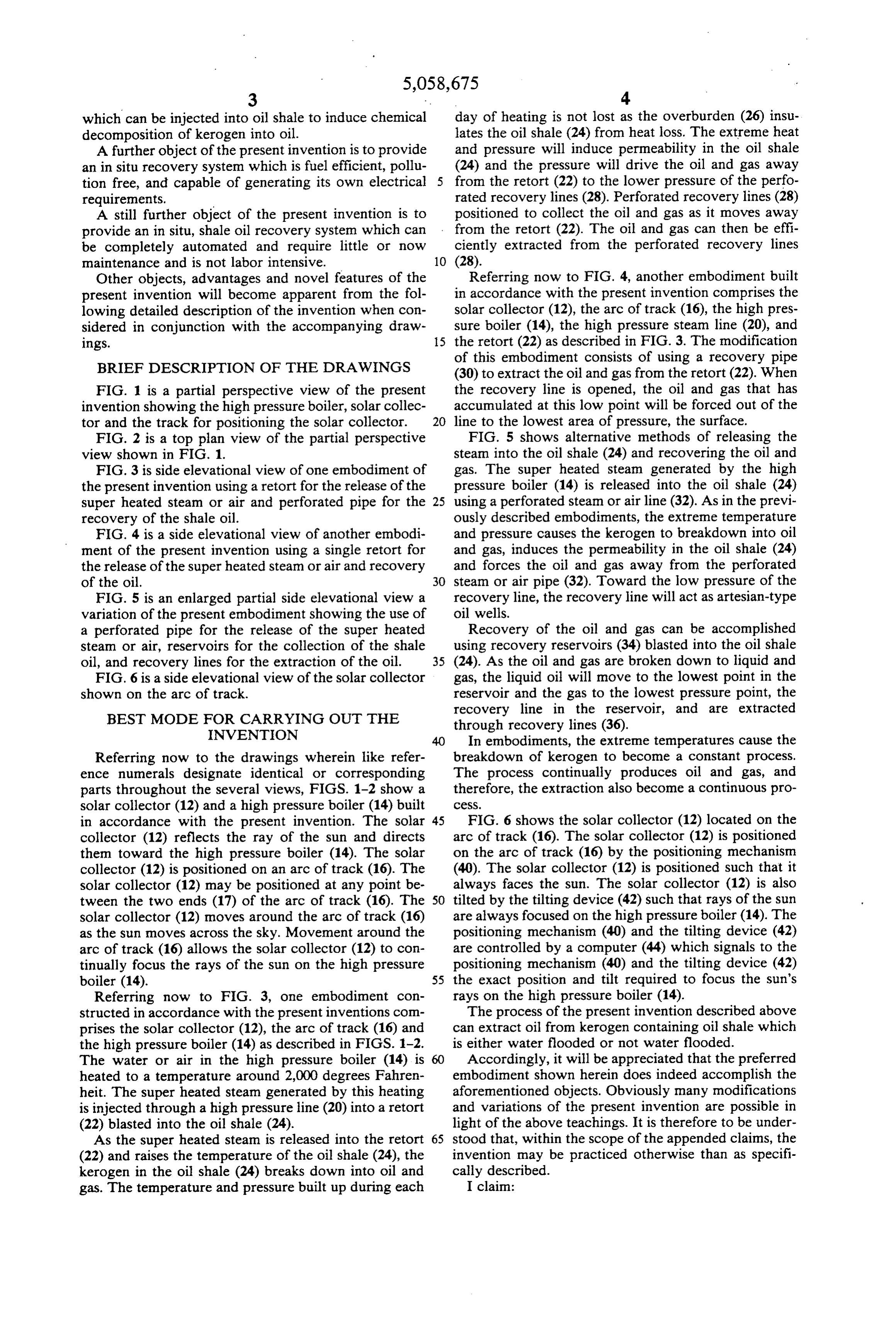
which can be injected into oil shale to induce chemical day of heating is not lost as the overburden (26) insu decomposition of kerogen into oil. lates the oil shale (24) from heat loss. The extreme heat A further object of the present invention is to provide and pressure will induce permeability in the oil shale an in situ recovery system which is fuel efficient, pollu (24) and the pressure will drive the oil and gas away tion free, and capable of generating its own electrical 5 from the retort (22) to the lower pressure of the perfo requirements. rated recovery lines (28). Perforated recovery lines (28) A still further object of the present invention is to positioned to collect the oil and gas as it moves away provide an in situ, shale oil recovery system which can from the retort (22). The oil and gas can then be effi be completely automated and require little or now ciently extracted from the perforated recovery lines maintenance and is not labor intensive. 10 (28).
Other objects, advantages and novel features of the Referring now to FIG. 4, another embodiment built present invention will become apparent from the fol in accordance with the present invention comprises the lowing detailed description of the invention when con solar collector (12), the arc of track (16), the high pres sidered in conjunction with the accompanying draw sure boiler (14), the high pressure steam line (20), and 1ngS. 15 the retort (22) as described in FIG. 3. The modification
BRIEF DESCRIPTION OF THE DRAWINGS
of this embodiment consists of using a recovery pipe (30) to extract the oil and gas from the retort (22). When
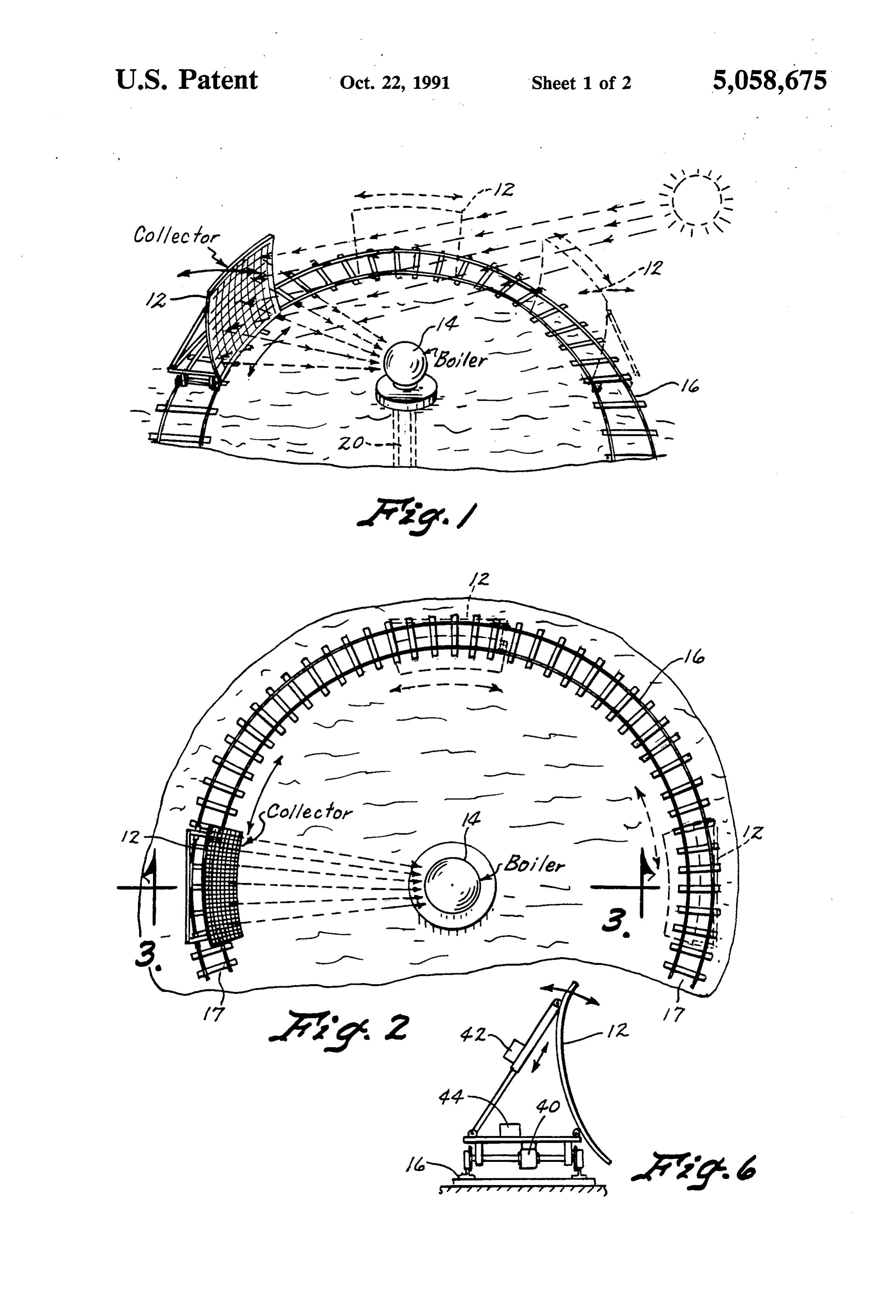
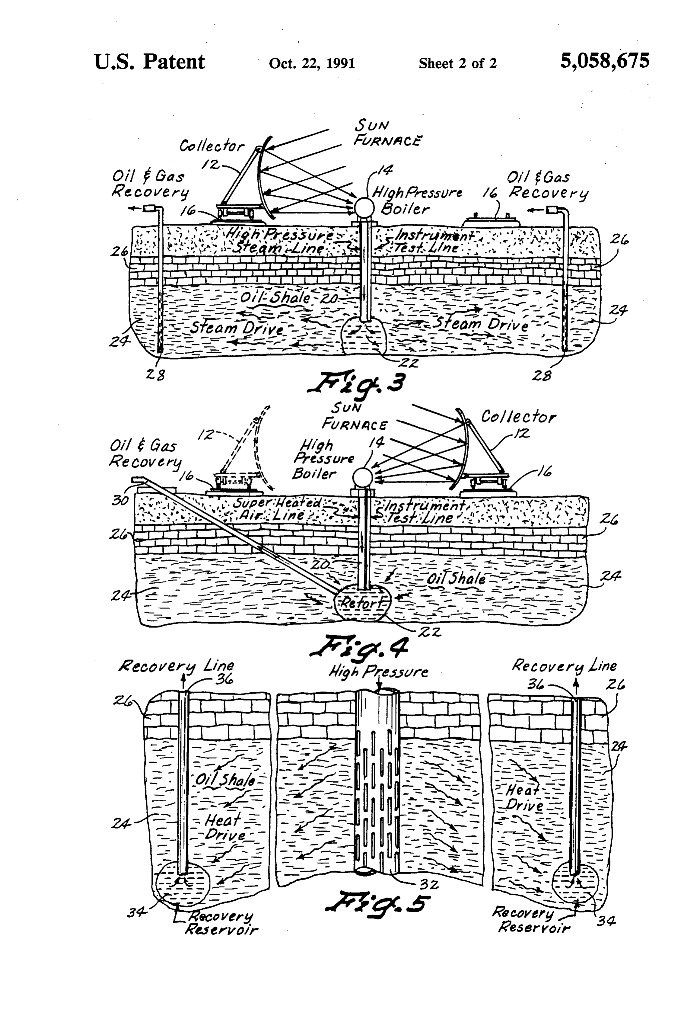
FIG. 1 is a partial perspective view of the present the recovery line is opened, the oil and gas that has invention showing the high pressure boiler, solar collec accumulated at this low point will be forced out of the tor and the track for positioning the solar collector. 20 line to the lowest area of pressure, the surface. FIG. 2 is a top plan view of the partial perspective FIG. 5 shows alternative methods of releasing the view shown in FIG. 1. steam into the oil shale (24) and recovering the oil and FIG. 3 is side elevational view of one embodiment of gas. The super heated steam generated by the high the present invention using a retort for the release of the pressure boiler (14) is released into the oil shale (24) super heated steam or air and perforated pipe for the 25 using a perforated steam or air line (32). As in the previ recovery of the shale oil. ously described embodiments, the extreme temperature FIG. 4 is a side elevational view of another embodi and pressure causes the kerogen to breakdown into oil ment of the present invention using a single retort for and gas, induces the permeability in the oil shale (24) the release of the super heated steam or air and recovery and forces the oil and gas away from the perforated of the oil. 30 steam or air pipe (32). Toward the low pressure of the FIG. 5 is an enlarged partial side elevational view a recovery line, the recovery line will act as artesian-type variation of the present embodiment showing the use of oil wells.
a perforated pipe for the release of the super heated Recovery of the oil and gas can be accomplished steam or air, reservoirs for the collection of the shale using recovery reservoirs (34) blasted into the oil shale oil, and recovery lines for the extraction of the oil. 35 (24). As the oil and gas are broken down to liquid and FIG. 6 is a side elevational view of the solar collector gas, the liquid oil will move to the lowest point in the shown on the arc of track. reservoir and the gas to the lowest pressure point, the
BEST MODE FOR CARRYING OUT THE
recovery line in the reservoir, and are extracted
INVENTION
through recovery lines (36).
In embodiments, the extreme temperatures cause the
Referring now to the drawings wherein like refer breakdown of kerogen to become a constant process. ence numerals designate identical or corresponding The process continually produces oil and gas, and parts throughout the several views, FIGS. 1-2 show a therefore, the extraction also become a continuous pro solar collector (12) and a high pressure boiler (14) built CCSS.
in accordance with the present invention. The solar 45 FIG. 6 shows the solar collector (12) located on the collector (12) reflects the ray of the sun and directs arc of track (16). The solar collector (12) is positioned them toward the high pressure boiler (14). The solar on the arc of track (16) by the positioning mechanism collector (12) is positioned on an arc of track (16). The (40). The solar collector (12) is positioned such that it solar collector (12) may be positioned at any point be always faces the sun. The solar collector (12) is also tween the two ends (17) of the arc of track (16). The 50 tilted by the tilting device (42) such that rays of the sun solar collector (12) moves around the arc of track (16) are always focused on the high pressure boiler (14). The as the sun moves across the sky. Movement around the positioning mechanism (40) and the tilting device (42) arc of track (16) allows the solar collector (12) to con are controlled by a computer (44) which signals to the tinually focus the rays of the sun on the high pressure positioning mechanism (40) and the tilting device (42) boiler (14). 55 the exact position and tilt required to focus the sun's Referring now to FIG. 3, one embodiment con rays on the high pressure boiler (14).
structed in accordance with the present inventions com The process of the present invention described above prises the solar collector (12), the arc of track (16) and can extract oil from kerogen containing oil shale which the high pressure boiler (14) as described in FIGS. 1-2. is either water flooded or not water flooded. The water or air in the high pressure boiler (14) is Accordingly, it will be appreciated that the preferred heated to a temperature around 2,000 degrees Fahren embodiment shown herein does indeed accomplish the heit. The super heated steam generated by this heating aforementioned objects. Obviously many modifications is injected through a high pressure line (20) into a retort and variations of the present invention are possible in (22) blasted into the oil shale (24). light of the above teachings. It is therefore to be under As the super heated steam is released into the retort 65 stood that, within the scope of the appended claims, the (22) and raises the temperature of the oil shale (24), the invention may be practiced otherwise than as specifi kerogen in the oil shale (24) breaks down into oil and cally described.
gas. The temperature and pressure built up during each I claim:
Page 6
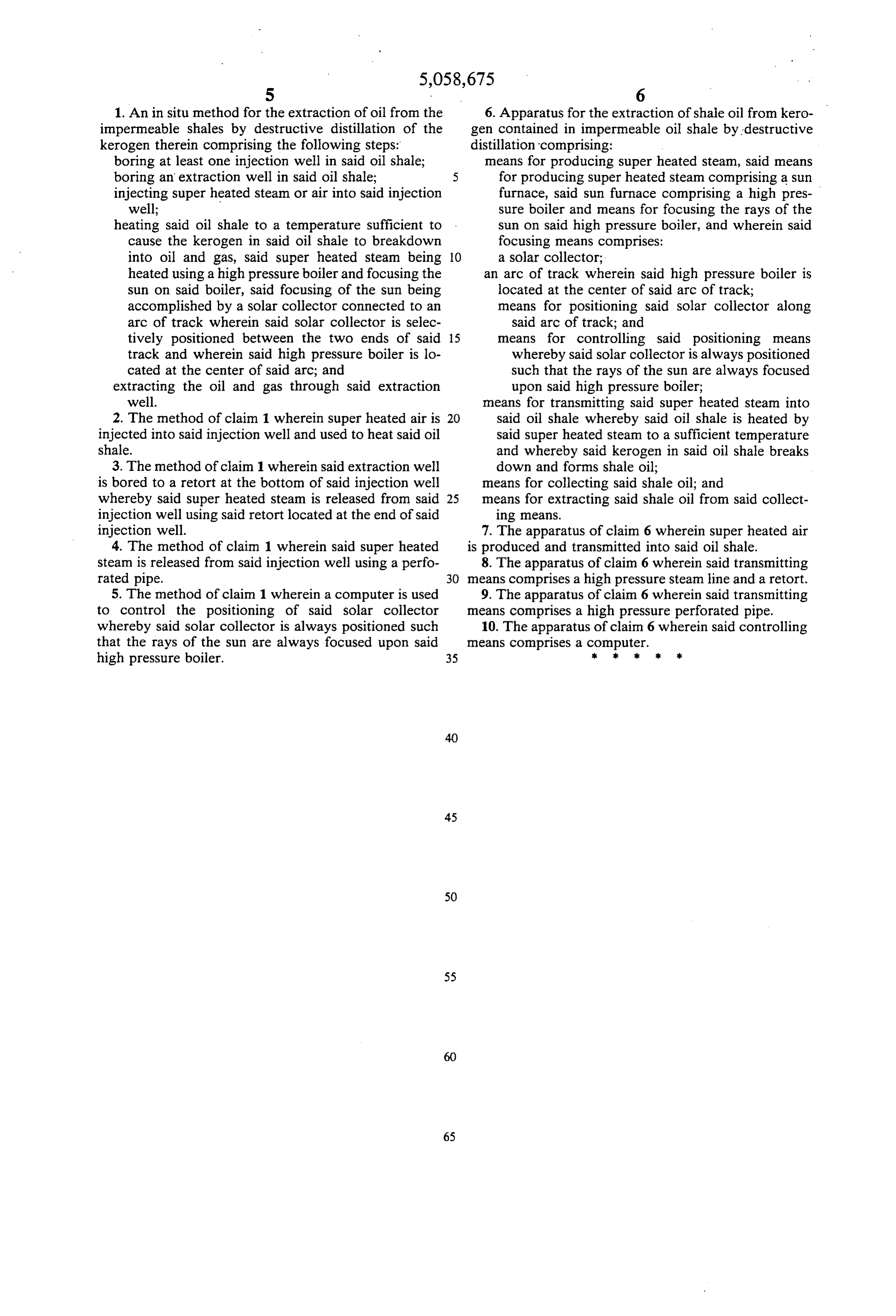
1. An in situ method for the extraction of oil from the 6. Apparatus for the extraction of shale oil from kero impermeable shales by destructive distillation of the gen contained in impermeable oil shale by destructive kerogen therein comprising the following steps: distillation comprising:
boring at least one injection well in said oil shale; means for producing super heated steam, said means boring an extraction well in said oil shale; 5 for producing super heated steam comprising a sun injecting super heated steam or air into said injection furnace, said sun furnace comprising a high pres well; sure boiler and means for focusing the rays of the heating said oil shale to a temperature sufficient to Sun on said high pressure boiler, and wherein said cause the kerogen in said oil shale to breakdown focusing means comprises:
into oil and gas, said super heated steam being 10 a solar collector;
heated using a high pressure boiler and focusing the an arc of track wherein said high pressure boiler is sun on said boiler, said focusing of the sun being located at the center of said arc of track; accomplished by a solar collector connected to an means for positioning said solar collector along arc of track wherein said solar collector is selec said arc of track; and tively positioned between the two ends of said 15 means for controlling said positioning means track and wherein said high pressure boiler is lo whereby said solar collector is always positioned cated at the center of said arc; and such that the rays of the sun are always focused extracting the oil and gas through said extraction upon said high pressure boiler; well. means for transmitting said super heated steam into 2. The method of claim 1 wherein super heated air is 20 said oil shale whereby said oil shale is heated by injected into said injection well and used to heat said oil said super heated steam to a sufficient temperature shale. and whereby said kerogen in said oil shale breaks 3. The method of claim 1 wherein said extraction well down and forms shale oil;
is bored to a retort at the bottom of said injection well means for collecting said shale oil; and whereby said super heated steam is released from said 25 means for extracting said shale oil from said collect injection well using said retort located at the end of said ing means.
injection well. 7. The apparatus of claim 6 wherein super heated air 4. The method of claim 1 wherein said super heated is produced and transmitted into said oil shale. steam is released from said injection well using a perfo 8. The apparatus of claim 6 wherein said transmitting rated pipe. 30 means comprises a high pressure steam line and a retort. 5. The method of claim 1 wherein a computer is used 9. The apparatus of claim 6 wherein said transmitting to control the positioning of said solar collector means comprises a high pressure perforated pipe. whereby said solar collector is always positioned such 10. The apparatus of claim 6 wherein said controlling that the rays of the sun are always focused upon said eaS comprises a computer.
high pressure boiler. 35 k . . . .
Provenance
- Collection
- Cited prior art
- Original PDF
- patentimages.storage.googleapis.com →
- Filed
- 1990-10-29
- Pages
- 6
- Method
- pdftotext (the PDF's own text layer) + pdftoppm 300dpi page scans
- Source
- Google Patents bibliographic record
- Granted
- 1991-10-22
- Inventors
- Elmer E. Travis
- Transcribed from
- patentimages.storage.googleapis.com →