patent · US4896507
Solar power system
30 January 1990
Page 1 — bibliographic record
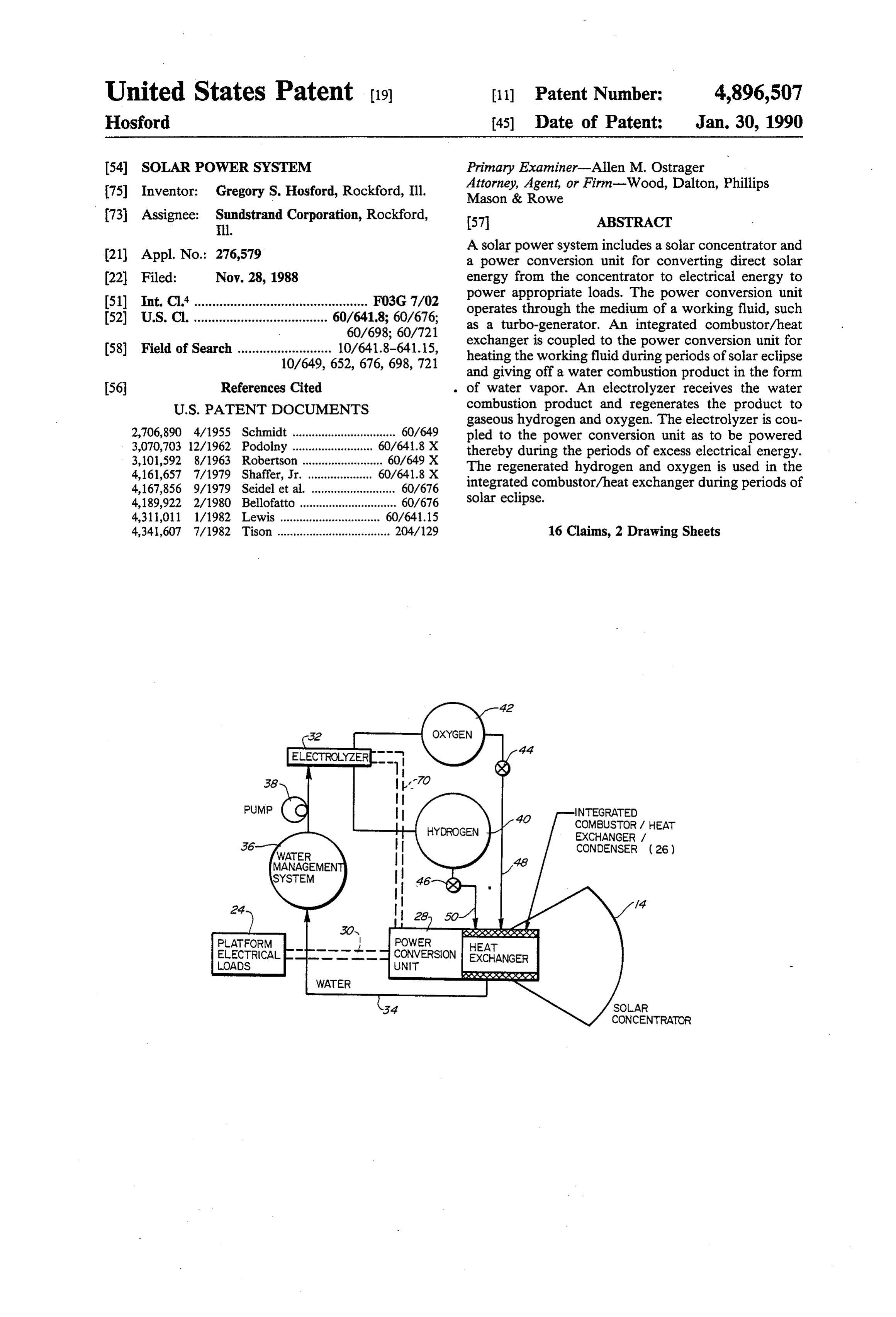
United States Patent (19) 11) Patent Number: 4,896,507 Hosford 45) Date of Patent: Jan. 30, 1990 54 SOLAR POWER SYSTEM Primary Examiner-Allen M. Ostrager Attorney, Agent, or Firm-Wood, Dalton, Phillips (75) Inventor: Gregory S. Hosford, Rockford, Ill. Mason & Rowe 73 Assignee: Sundstrand Corporation, Rockford, 57 ABSTRACT
(21) Appl. No.: 276,579 A solar power system includes a solar concentrator and a power conversion unit for converting direct solar (22 Filed: Nov. 28, 1988 energy from the concentrator to electrical energy to 51 Int. Cl. ................................................ FO3G 7/02 power appropriate loads. The power conversion unit 52 U.S.C. ..................................... 60/641,8; 60/676; operates through the medium of a working fluid, such 60/698; 60/721 as a turbo-generator. An integrated combustor/heat 58) Field of Search .......................... 10/641.8-641.15, exchanger is coupled to the power conversion unit for 10/649, 652, 676, 698, 721 heating the working fluid during periods of solar eclipse and giving off a water combustion product in the form 56 References Cited of water vapor. An electrolyzer receives the water
gaseous hydrogen and oxygen. The electrolyzer is cou 2,706,890 4/1955 Schmidt ................................ 60/649 pled to the power conversion unit as to be powered 3,070,703 12/1962 Podolny ..... 60/64.8 X thereby during the periods of excess electrical energy. 3,101,592 8/1963 Robertson ...... ... 60/649 X The regenerated hydrogen and oxygen is used in the 4,161,657 7/1979 Shaffer, Jr. ... 60/641.8 X integrated combustor/heat exchanger during periods of 4,167,856 9/1979 Seidel et al. .......................... 60/676 4,189,922 2/1980 Bellofatto... ... 60/67.6 solar eclipse.
4,311,011 1/1982 Lewis ......... ... 60/641.15 4,341,607 7/1982 Tison ................................... 204/129 16 Claims, 2 Drawing Sheets
INTEGRATED
COMBUSTORA HEA
EXCHANGERA
CONDENSER (26)
SOAR
CONCENTRATOR
Page 2
PRIOR ART
PARASTIC
LOAD
RADATOR
PLATFORM 1 1/2
ELECTRICAL
PHASE CHANGE
XYYXSSXXXXXXS.
HEAT
EXCHANGER
l SOLAR
CONCENTRATOR
FIG 3 OXYGEN
HYDROGEN
NTEGRATED
COMBUS OR /
HEAT EXCHANGER
WORKING
FLUD
TO POWER
CONVERSION
DEVICE
Page 3
Drawing sheet — no readable text.
Page 4
combustion in the integrated combustor/heat ex
SOLAR POWER SYSTEM changer during periods of solar eclipse.
In addition, a condenser is provided for receiving the
FIELD OF THE INVENTION water combustion product from the integrated combus This invention generally relates to solar power sys tor/heat exchanger and condensing the product to satu tems and, particularly, to a solar power system which rated liquid for supply to the electrolyzer. An accumu provides immediate energy during direct solar exposure lator is coupled between the condenser and the electro and also provides energy which may be stored for peri lyzer. The working fluid for the power conversion unit ods of solar eclipse. 10 is passed through the condenser for absorbing heat from
BACKGROUND OF THE INVENTION condensation of the water combustion product. The working fluid first is passed through the condenser and
Various space applications are designed in such a way then through the integrated combustor/heat exchanger that the device continuously produces electrical power for absorbing heat of the hydrogen/oxygen combus even when that power is not needed. For example, 15 tion. Means also are provided for storing the hydrogen when a satellite or space station passes through its inso and oxygen from the electrolyzer during periods of lation phase, it is likely to have more solar power avail excess electrical energy for supply to the integrated able than is required for use. Some solar power systems combustor/heat exchanger during periods of solar of this type generally operate turbines at full power eclipse.
levels for purposes of efficiency and, as a result, must "dump' a portion of the electrical power produced. 20 tionOther will objects, features and advantages of the inven be apparent from the following detailed de
In order to provide continuously operable systems, scription taken in connection with the accompanying phase change materials have been used to act as a stor drawings.
age medium by absorbing heat and melting, followed by a rise in its temperature. When energy is needed, heat is BRIEF DESCRIPTION OF THE DRAWINGS given off by the phase change material as it decreases its 25 The features of this invention which are believed to temperature, followed by solidification. These systems essentially provide a battery-like device to store energy be novel are set forth with particularity in the appended as the space vehicle orbits the earth and passes through claims. The invention, together with its objects and the periods of insolation and solar eclipse. advantages thereof, may be best understood by refer In other systems, such as that shown in U.S. Pat. No. 30 ence to the following description taken in conjunction 4,341,607 to Tison, dated July 27, 1982, a photovoltaic with the accompanying drawings, in which like refer array is electrically connected to a voltage-dependent ence numerals identify like elements in the figures and variable resistance load in the form of a water electroly in which:
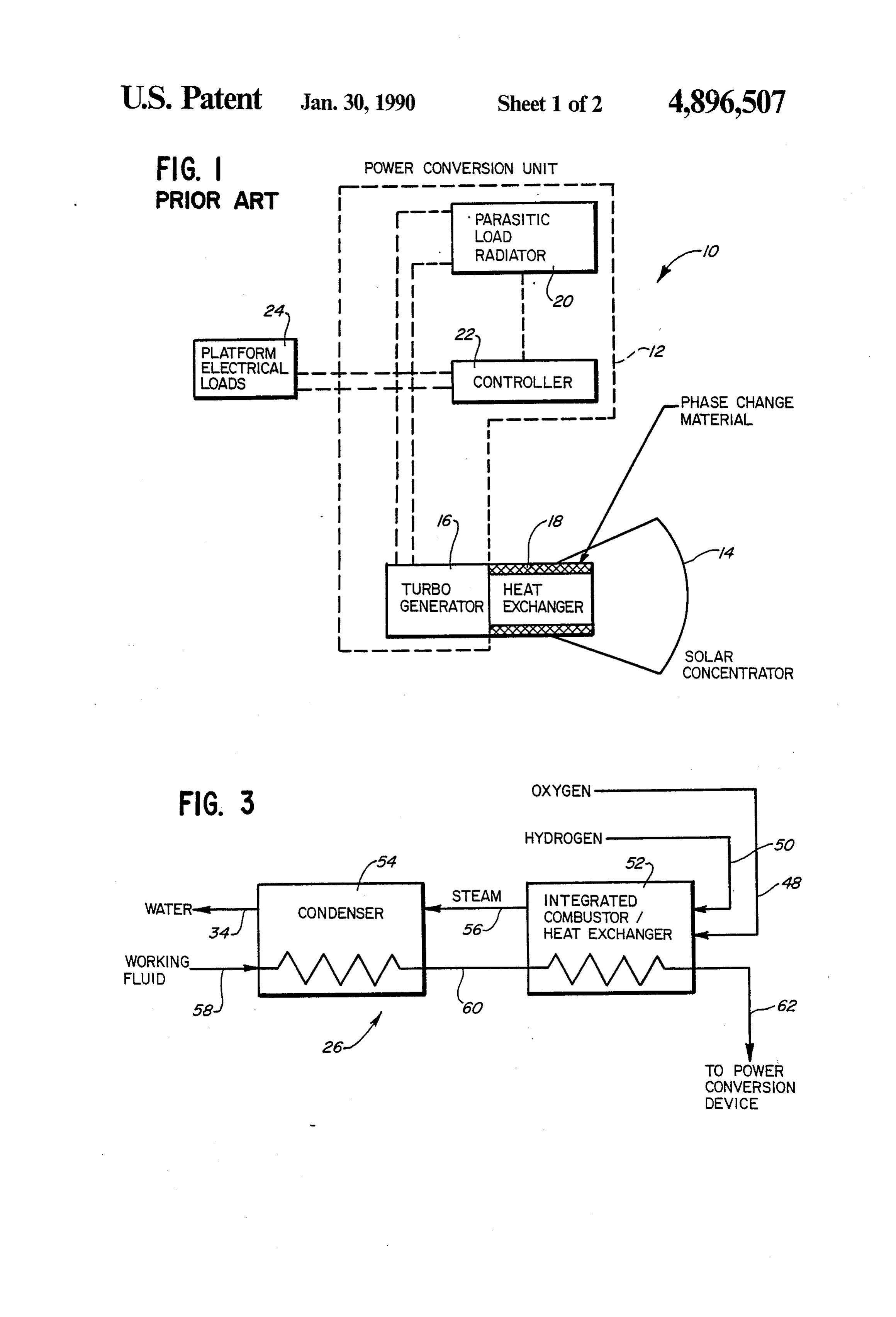
sis unit. This arrangement is used in a solar power sys FIG. 1 is a schematic illustration representing a solar tem which transfers electrical energy from a solar array 35 power system of the prior art;
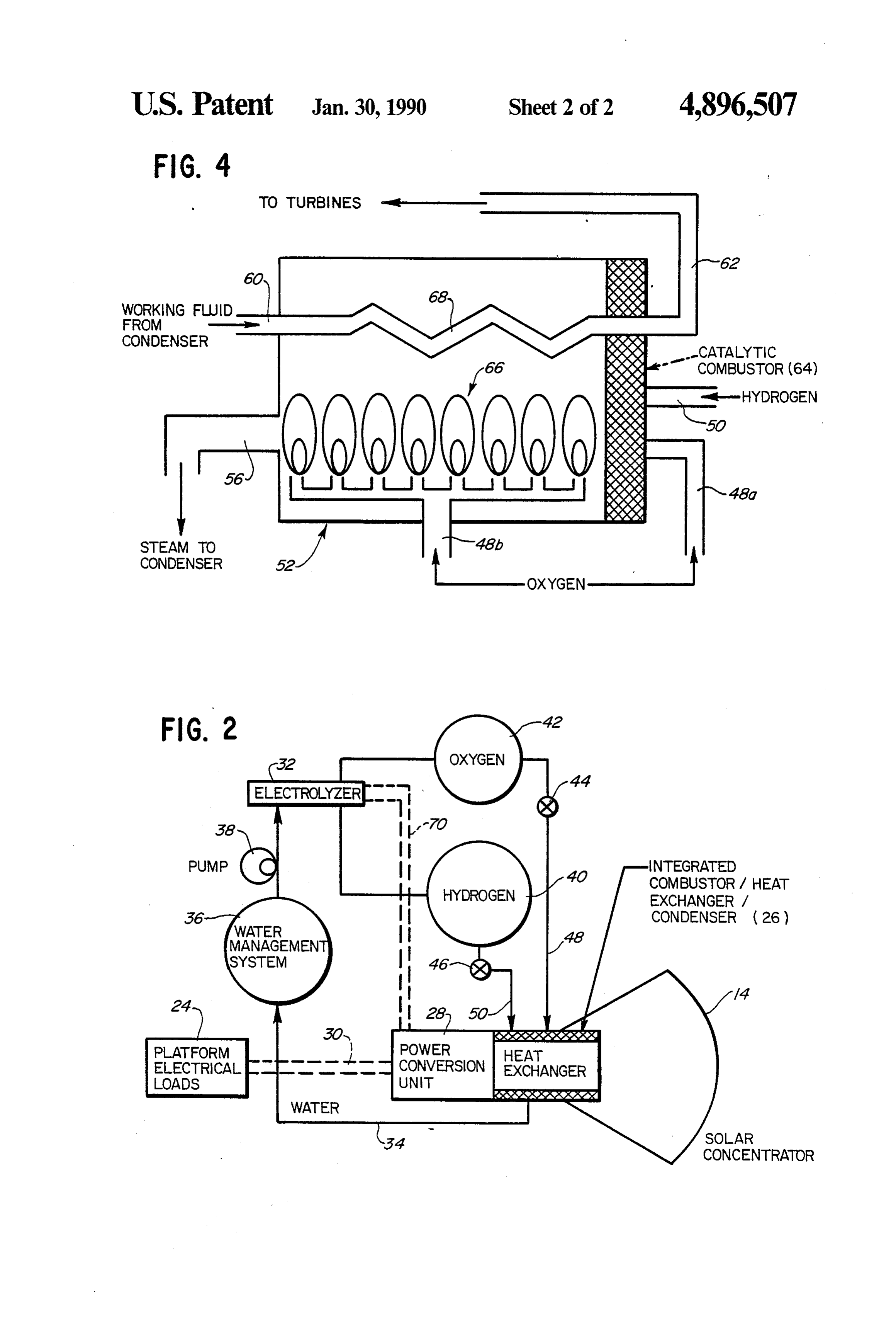
to a water electrolysis unit for energy storage and to a FIG. 2 is a schematic illustration representing the DC to AC inverter for immediate consumption while solar power system of the invention;
maintaining the photovoltaic array power within a few FIG. 3 is a schematic illustration of the "heat ex per cent of its peak power point. Hydrogen from elec changer' block shown in FIG. 2; and trolysis is used as a fuel for a hydrogen engine and steam FIG. 4 is a schematic illustration of the integrated is recirculated to a water reservoir to be reused in the combustor/heat exchanger shown in the right portion electrolyzer. of FIG, 3.
The present invention is directed to a new and in proved solar power system which utilizes an electro DETAILED DESCRIPTION OF THE lyzer, but an integrated combustor/heat exchanger is 45 PREFERRED EMBODIMENT fueled by hydrogen/oxygen from the electrolyzer to Referring to the drawings in greater detail, and first heat a working fluid of a motive means which is the to FIG. 1, a block diagram of a typical solar dynamic same motive means used in the radiant-to-electrical energy converter device. power system of the prior art is illustrated and generally 50 designated 10. The components within dotted line 12
SUMMARY OF THE INVENTION form a power conversion unit. In a conventional solar An object, therefore, of the invention is to provide a dynamic power system, a solar concentrator 14, such as new and improved solar power system which continues aergy segmented parabolic mirror, concentrates solar en to drive a turbo-generator 16, heating the turbine to provide power even during periods of solar eclipse. working fluid through a heat exchanger 18. The system In the exemplary embodiment of the invention, the 55 stores some of the heat from concentrator 14 as heat of solar power system includes a solar concentrator, with power conversion means for converting solar energy fusion by melting a phase change material (PCM) from the concentrator to electrical energy to power within the heat exchanger. Lithium fluoride is an exam appropriate loads, through the medium of a working ple of a phase change material. The PCM later releases fluid. An integrated combustor/heat exchanger is cou 60 this heat of fusion providing energy to drive turbo-gen pled to the power conversion unit for heating the work erator 16 during periods of solar eclipse. In order to ing fluid during periods of solar eclipse and giving off a maximize turbine efficiency and eliminate generator water combustion product. An electrolyzer receives the output power fluctuations as the power requirements of water combustion product and regenerates it to gaseous a space platform, for instance, change, the turbo-gener hydrogen and oxygen. The electrolyzer is coupled to 65 ator operates continuously at its rated output power. the power conversion means as to be powered thereby The system "dumps' its excess electrical power to during periods of excess electrical energy. Means are space through an electrical resistor bank that is ther provided for supplying the hydrogen and oxygen for mally connected to radiators 20. The energy from tur
Page 5
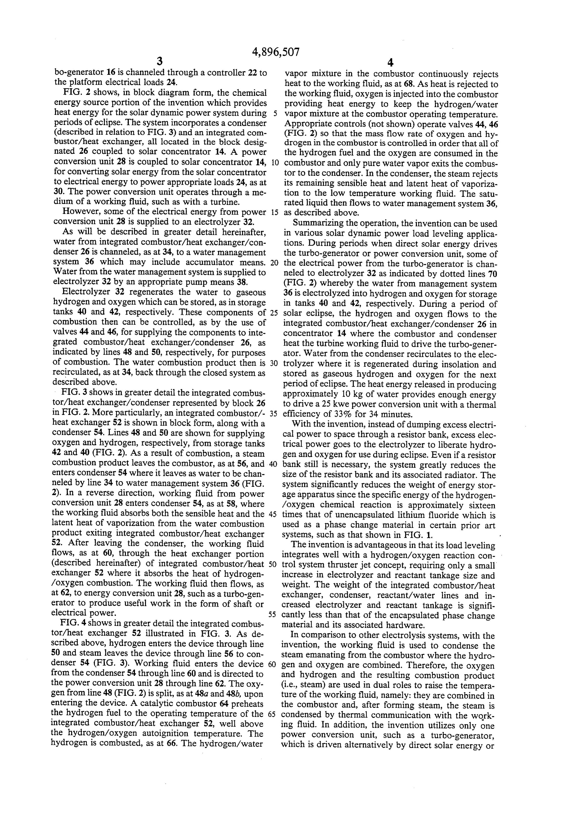
bo-generator 16 is channeled through a controller 22 to vapor mixture in the combustor continuously rejects the platform electrical loads 24. heat to the working fluid, as at 68. As heat is rejected to FIG. 2 shows, in block diagram form, the chemical the working fluid, oxygen is injected into the combustor energy source portion of the invention which provides providing heat energy to keep the hydrogen/water heat energy for the solar dynamic power system during vapor mixture at the combustor operating temperature. periods of eclipse. The system incorporates a condenser Appropriate controls (not shown) operate valves 44, 46 (described in relation to FIG. 3) and an integrated com (FIG. 2) so that the mass flow rate of oxygen and hy bustor/heat exchanger, all located in the block desig drogen in the combustor is controlled in order that all of nated 26 coupled to solar concentrator 14. A power the hydrogen fuel and the oxygen are consumed in the conversion unit 28 is coupled to solar concentrator 14, O combustor and only pure water vapor exits the combus for converting solar energy from the solar concentrator tor to the condenser. In the condenser, the steam rejects to electrical energy to power appropriate loads 24, as at its remaining sensible heat and latent heat of vaporiza 30. The power conversion unit operates through a me tion to the low temperature working fluid. The satu dium of a working fluid, such as with a turbine. rated liquid then flows to water management system 36, However, some of the electrical energy from power 15 as described above.
conversion unit 28 is supplied to an electrolyzer 32. Summarizing the operation, the invention can be used As will be described in greater detail hereinafter, in various solar dynamic power load leveling applica water from integrated combustor/heat exchanger/con tions. During periods when direct solar energy drives denser 26 is channeled, as at 34, to a water management the turbo-generator or power conversion unit, some of system 36 which may include accumulator means. 20 the electrical power from the turbo-generator is chan Water from the water management system is supplied to neled to electrolyzer 32 as indicated by dotted lines 70 electrolyzer 32 by an appropriate pump means 38. (FIG. 2) whereby the water from management system Electrolyzer 32 regenerates the water to gaseous 36 is electrolyzed into hydrogen and oxygen for storage hydrogen and oxygen which can be stored, as in storage in tanks 40 and 42, respectively. During a period of tanks 40 and 42, respectively. These components of 25 solar eclipse, the hydrogen and oxygen flows to the combustion then can be controlled, as by the use of integrated combustor/heat exchanger/condenser 26 in valves 44 and 46, for supplying the components to inte concentrator 14 where the combustor and condenser grated combustor/heat exchanger/condenser 26, as heat the turbine working fluid to drive the turbo-gener indicated by lines 48 and 50, respectively, for purposes ator. Water from the condenser recirculates to the elec of combustion. The water combustion product then is 30 trolyzer where it is regenerated during insolation and recirculated, as at 34, back through the closed system as stored as gaseous hydrogen and oxygen for the next described above. period of eclipse. The heat energy released in producing FIG.3 shows in greater detail the integrated combus approximately 10 kg of water provides enough energy tor/heat exchanger/condenser represented by block 26 to drive a 25 kwe power conversion unit with a thermal in FIG. 2. More particularly, an integrated combustor/- 35 efficiency of 33% for 34 minutes. heat exchanger 52 is shown in block form, along with a With the invention, instead of dumping excess electri condenser 54. Lines 48 and 50 are shown for supplying cal power to space through a resistor bank, excess elec oxygen and hydrogen, respectively, from storage tanks trical power goes to the electrolyzer to liberate hydro 42 and 40 (FIG. 2). As a result of combustion, a steam gen and oxygen for use during eclipse. Even if a resistor combustion product leaves the combustor, as at 56, and bank still is necessary, the system greatly reduces the enters condenser 54 where it leaves as water to be chan size of the resistor bank and its associated radiator. The neled by line 34 to water management system 36 (FIG. system significantly reduces the weight of energy stor 2). In a reverse direction, working fluid from power age apparatus since the specific energy of the hydrogen conversion unit 28 enters condenser 54, as at 58, where /oxygen chemical reaction is approximately sixteen the working fluid absorbs both the sensible heat and the 45 times that of unencapsulated lithium fluoride which is latent heat of vaporization from the water combustion used as a phase change material in certain prior art product exiting integrated combustor/heat exchanger systems, such as that shown in FIG. 1. 52. After leaving the condenser, the working fluid The invention is advantageous in that its load leveling flows, as at 60, through the heat exchanger portion integrates well with a hydrogen/oxygen reaction con (described hereinafter) of integrated combustor/heat 50 trol system thruster jet concept, requiring only a small exchanger 52 where it absorbs the heat of hydrogen increase in electrolyzer and reactant tankage size and /oxygen combustion. The working fluid then flows, as weight. The weight of the integrated combustor/heat at 62, to energy conversion unit 28, such as a turbo-gen exchanger, condenser, reactant/water lines and in erator to produce useful work in the form of shaft or creased electrolyzer and reactant tankage is signifi electrical power. 55 cantly less than that of the encapsulated phase change FIG. 4 shows in greater detail the integrated combus material and its associated hardware. tor/heat exchanger 52 illustrated in FIG. 3. As de In comparison to other electrolysis systems, with the scribed above, hydrogen enters the device through line invention, the working fluid is used to condense the 50 and steam leaves the device through line 56 to con steam emanating from the combustor where the hydro denser 54 (FIG. 3). Working fluid enters the device 60 gen and oxygen are combined. Therefore, the oxygen from the condenser 54 through line 60 and is directed to and hydrogen and the resulting combustion product the power conversion unit 28 through line 62. The oxy (i.e., steam) are used in dual roles to raise the tempera gen from line 48 (FIG. 2) is split, as at 48a and 48b, upon ture of the working fluid, namely: they are combined in entering the device. A catalytic combustor 64 preheats the combustor and, after forming steam, the steam is the hydrogen fuel to the operating temperature of the 65 condensed by thermal communication with the work integrated combustor/heat exchanger 52, well above ing fluid. In addition, the invention utilizes only one the hydrogen/oxygen autoignition temperature. The power conversion unit, such as a turbo-generator, hydrogen is combusted, as at 66. The hydrogen/water which is driven alternatively by direct solar energy or
Page 6
by the combination of hydrogen and oxygen. Further condenser means for receiving the water combustion more, hydrogen in the subject invention is not used as a product from the integrated combustor/heat ex working fluid and the hydrogen/oxygen combustion changer means and condensing the product to satu products are not directly used to drive some load. rated liquid for supply to the electrolyzer means; It will be understood that the invention may be em 5 electrolyzer means for receiving the water combus bodied in other specific forms without departing from tion product from the condenser means and regen the spirit or central characteristics thereof. The present erating the water combustion product to gaseous examples and embodiments, therefore, are to be consid hydrogen and oxygen, the electrolyzer means ered in all respects as illustrative and not restrictive, and being coupled to the power conversion means as to the invention is not to be limited to the details given 10 be powered thereby during periods of excess elec herein. trical energy; and
What is claimed is: means for storing the hydrogen and oxygen from the 1. A solar power system, comprising: electrolyzer means during periods of direct solar solar concentrator means; energy for supply to the integrated combustor/- power conversion means for converting solar energy 15 heat exchanger means during periods of solar from the solar concentrator means to electrical eclipse.
8. The energy, through the medium of a working fluid, to accumulator solar power system of claim 7, including water power appropriate loads; means coupled between the condenser integrated combustor/heat exchanger means coupled 20 means and the electrolyzer means. 9. The solar power system of claim 7, including to the power conversion means for heating said means for passing said working fluid through the con working fluid during periods of solar eclipse and denser means for absorbing heat from condensation of giving off a water combustion product; the water combustion product.
electrolyzer means for receiving the water combus 10. The solar power system of claim 9, including tion product from the integrated combustor/heat 25 means for passing said working fluid first through the exchanger means and regenerating the water com condenser means and then through the integrated com bustion product to gaseous hydrogen and oxygen, bustor/heat exchanger means for absorbing heat of the the electrolyzer means being coupled to the power hydrogen/oxygen combustion.
conversion means as to be powered thereby during 11. A solar power system, comprising: periods of excess electrical energy; and 30 working fluid power conversion means for convert means for supplying the hydrogen and oxygen for ing solar energy to power an appropriate load dur combustion in the integrated combustor/heat ex ing periods of direct solar energy; changer during said periods of solar eclipse. integrated combustor/heat exchanger means for 2. The solar power system of claim 1, including con combusting hydrogen and oxygen to heat the denser means for receiving the water combustion prod 35 working fluid during periods of solar eclipse, and uct from the integrated combustor/heat exchanger producing a water product of combustion; means and condensing the product to saturated liquid electrolyzer means for regenerating the water com for supply to the electrolyzer means. bustion product to gaseous hydrogen and oxygen 3. The solar power system of claim 2, including water for combustion in the integrated combustor/heat accumulator means coupled between the condenser exchanger means; and means and the electrolyzer means. means for coupling the electrolyzer means to the 4. The solar power system of claim 2, including power conversion means as to be powered thereby means for passing said working fluid through the con during the periods of excess electrical energy. denser means for absorbing heat from condensation of 12. The solar power system of claim 11, including the water combustion product. 5 condenser means for receiving the water combustion 5. The solar power system of claim 4, including product from the integrated combustor/heat exchanger means and condensing the combustion product to satu means for passing said working fluid first through the rated liquid for supply to the electrolyzer means. condenser means and then through the integrated com bustor/heat exchanger means for absorbing heat of the SO water The 13. solar power system of claim 12, including accumulator means coupled between the con hydrogen/oxygen combustion.
6. The solar power system of claim 1, including denser means and the electrolyzer means. 14. The solar power system of claim 12, including means for storing the hydrogen and oxygen from the means for passing said working fluid through the con electrolyzer means during periods of direct solar energy denser means for absorbing heat from condensation of for supply to the integrated combustor/heat exchanger 55 the water combustion product. means during periods of solar eclipse. 15. The solar power system of claim 14, including 7. A solar power system, comprising: means for passing said working fluid first through the solar concentrator means; condenser means and then through the integrated com power conversion means for converting solar energy bustor/heat exchanger means for absorbing heat of the from the solar concentrator means to electrical 60 hydrogen/oxygen combustion.
energy, through the medium of a working fluid, to 16. The solar power system of claim 11, including power appropriate loads; means for storing the hydrogen and oxygen from the integrated combustor/heat exchanger means coupled electrolyzer means during periods of direct solar energy to the power conversion means for heating said for supply to the integrated combustor/heat exchanger working fluid during periods of solar eclipse and 65 means during periods of solar eclipse. giving off a water combustion product; :
Provenance
- Collection
- Cited prior art
- Original PDF
- patentimages.storage.googleapis.com →
- Filed
- 1988-11-28
- Pages
- 6
- Method
- pdftotext (the PDF's own text layer) + pdftoppm 300dpi page scans
- Source
- Google Patents bibliographic record
- Granted
- 1990-01-30
- Inventors
- Gregory S. Hosford; Sundstrand Corp
- Transcribed from
- patentimages.storage.googleapis.com →