patent · US4881372
Stirling engine
21 November 1989
Page 1 — bibliographic record
United States Patent (19) (11) Patent Number: 4,881,372 Naito 45 Date of Patent: Nov. 21, 1989 54). STIRLING ENGINE FOREIGN PATENT DOCUMENTS 75 Inventor: Yoshihiro Naito, Nagoya, Japan 0.178545 8/1986 Japan ..................................... 60/524 73 Assignee: Aisin Seiki Kabushiki Kaisha, Kariya, Primary Examiner-Allen M. Ostrager Japan Attorney, Agent, or Firm-Burns, Doane, Swecker &
Mathis (21) Appl. No.: 316,853 57 ABSTRACT 22 Filed: Feb. 28, 1989 A Stirling engine includes a heater device for collecting solar radiation energy, a heater tube disposed in the 30 Foreign Application Priority Data heater device and connecting the expansion space and Feb. 29, 1988 JP Japan ................................ 63-048084 the compression space of cylinder containing a piston, and a transparent partition located in the heater device 51 Int. Cl." ................................................ F02G 1/04 for defining a closed space. A heat storage material is 52 U.S. Cl. ................................... 60/521; 60/641.14; positioned in the closed space and a temperature detect 60/641.8; 60/659; 60/524 ing apparatus is provided for detecting the temperature 58) Field of Search ................. 60/517,521, 522, 524, of the heat storage material. A pressure regulating ar 60/641.8, 641.14, 659 rangement regulates the pressure of a working gas in a working space located between the expansion space and 56) References Cited the compression space of the cylinder. A control device controls the pressure regulating arrangement in re
3,080,706 3/1963 Flynn, Jr. et al. .................... 60/659 ratuS.
4,126,995 11/1978 Asselman et al. ... ... 60/524 4,457,133 7/1984 Almstrom et al. .......... ... 60/524 8 Claims, 8 Drawing Sheets
ENXYNS
43XSSzizza-N57, N N N M NY
/ NINC E.s
Q. Nizzar 2
Page 2
Drawing sheet — no readable text.
Page 3
Drawing sheet — no readable text.
Page 4
Fig. 4
Y Abnormal Routine (Interrupt Qin)
Stop
the pressure -- of high level
Sting.
Metti
Constant under the pressure abs Of low level
(Idle pressure) Time The Engine is started at the optional point.
Page 5
Drawing sheet — no readable text.
Page 6
Drawing sheet — no readable text.
Page 7
Drawing sheet — no readable text.
Page 8
READ
Heat Storage Temp. T.
Engine Start;
SET Press: Idle
Heat Storage Tempt
READ Heat Quantity of READ Heat Quantity of Solar Solar Radiation energy Qin Radiation energy Qin CACULATE Balance Press. Pb CAL CULATE Balance Press. Pb SET Press. Pset: 307 SET Press. Pset: 314 Pset Pb + AP 308. Pset = Pb - AP 315
OPEN Inlet Wave OPEN Outlet Valve
CLOSE Inlet Valve CLOSE Outlet Valve
Page 9
Drawing sheet — no readable text.
Page 10
value. Thus, the output of the engine is maintained at a
However, since solar radiation varies abruptly in
BACKGROUND OF THE INVENTION magnitude, the temperature of the gas in the pipe varies 1. Field of the Invention in a similar manner. Thus, to maintain the temperature The present invention relates to a Stirling engine. of the pipe at a set value, the pressure of the gas must be More particularly, the present invention relates to a quickly adjusted in a precise manner. However, since solar-powered Stirling engine and a method for control the control of the pressure of the gas cannot be easily performed, the engine output becomes unstable. Fur ling the output of such an engine. 10 ther, in order to control the pressure of the gas in that 2. Description of Related Art manner, the valves for increasing the pressure and for U.S. Pat. No. 4,457,133 discloses a conventional so reducing the pressure should have a special construc lar-powered Stirling engine that includes a plurality of tion that permits the valves to be controlled in a precise cylinders. In each cylinder, a piston is movably manner and which permits a large amount of gas to be mounted and an expansion space and a compression 15 passed therethrough, However, the construction of space are defined across the piston. The compression such a valve can be very expensive.
space is in fluid communication with a neighboring expansion space via a heater, a regenerator and a cooler. SUMMARY OF THE INVENTION Reciprocal movements of each piston are converted It is, therefore, a principal object of the present inven into a rotating torque at an output mechanism and the 20 tion to provide a Stirling engine from which a stable or resulting torque is transmitted to a suitable mechanism a constant output can be obtained in spite of variations such as a dynamo. in solar radiation.
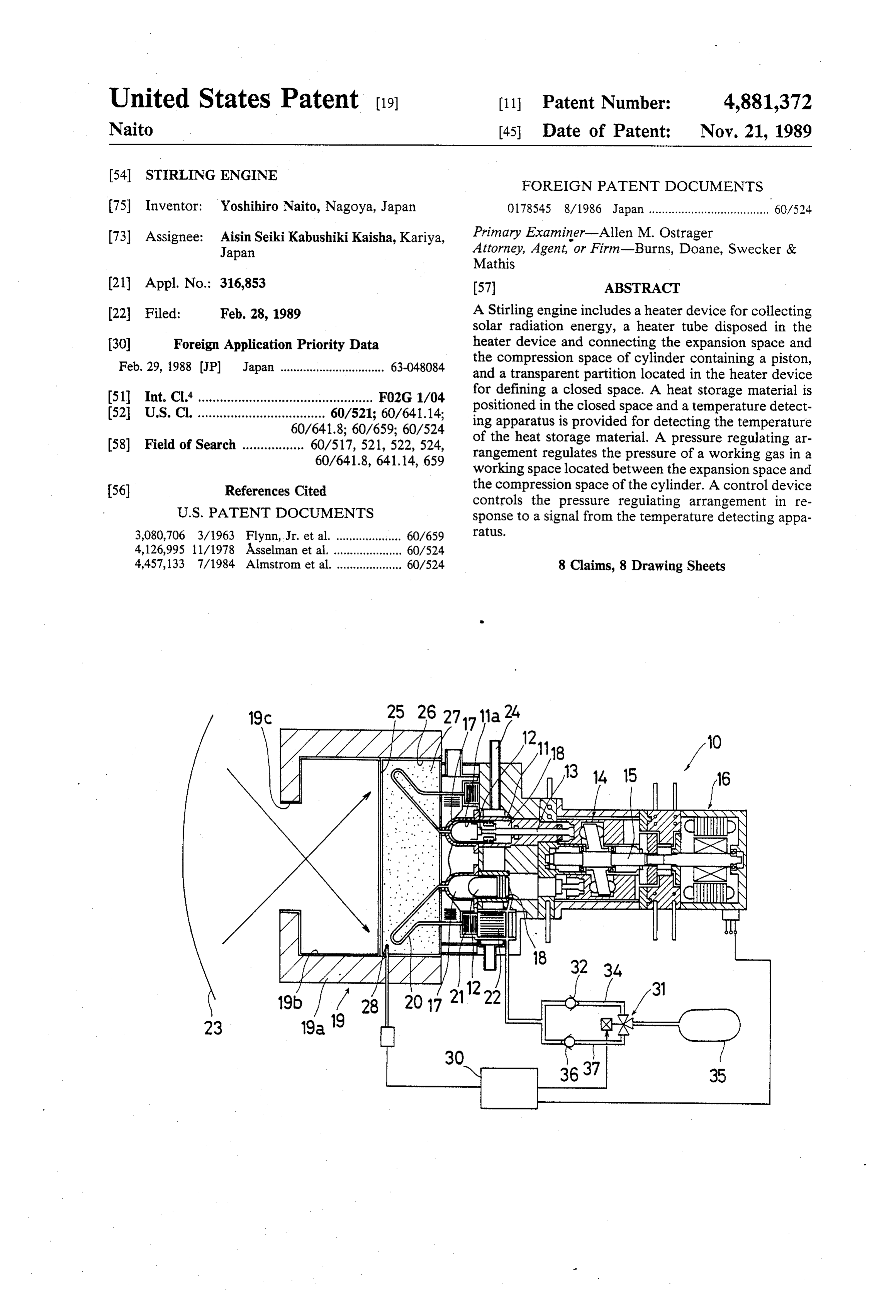
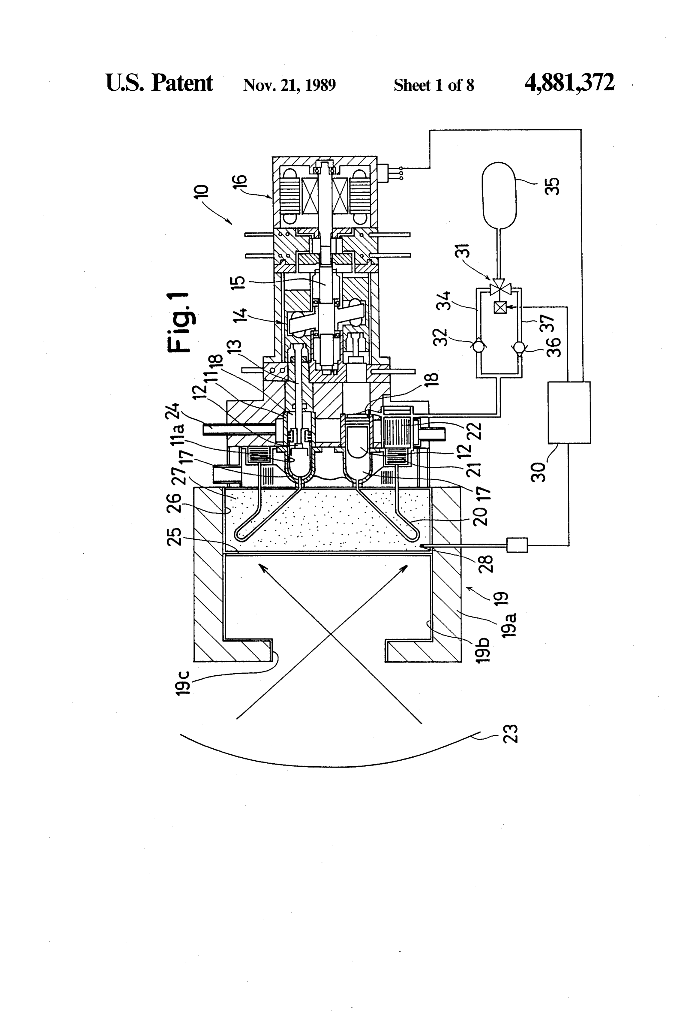
A working gas such as helium gas or hydrogen gas is BRIEF DESCRIPTION OF THE DRAWINGS filled in a working space that includes the expansion space, the compression space and the aforementioned 25 FIG. 1 is a cross-sectional view of a Stirling engine other members located therebetween, and the gas is according to one embodiment of the present invention; heated by solar radiation energy while it passes through FIG. 2 is a graph showing the relationship between pipes. The working space is connected to a gas-reser the temperature of the heat-storing material and an voir via a minimum-cycle-pressure line which includes integration of the term (solar radiation energy - quantity a check-valve and a pressure-increasing valve. The 30 of FIG.
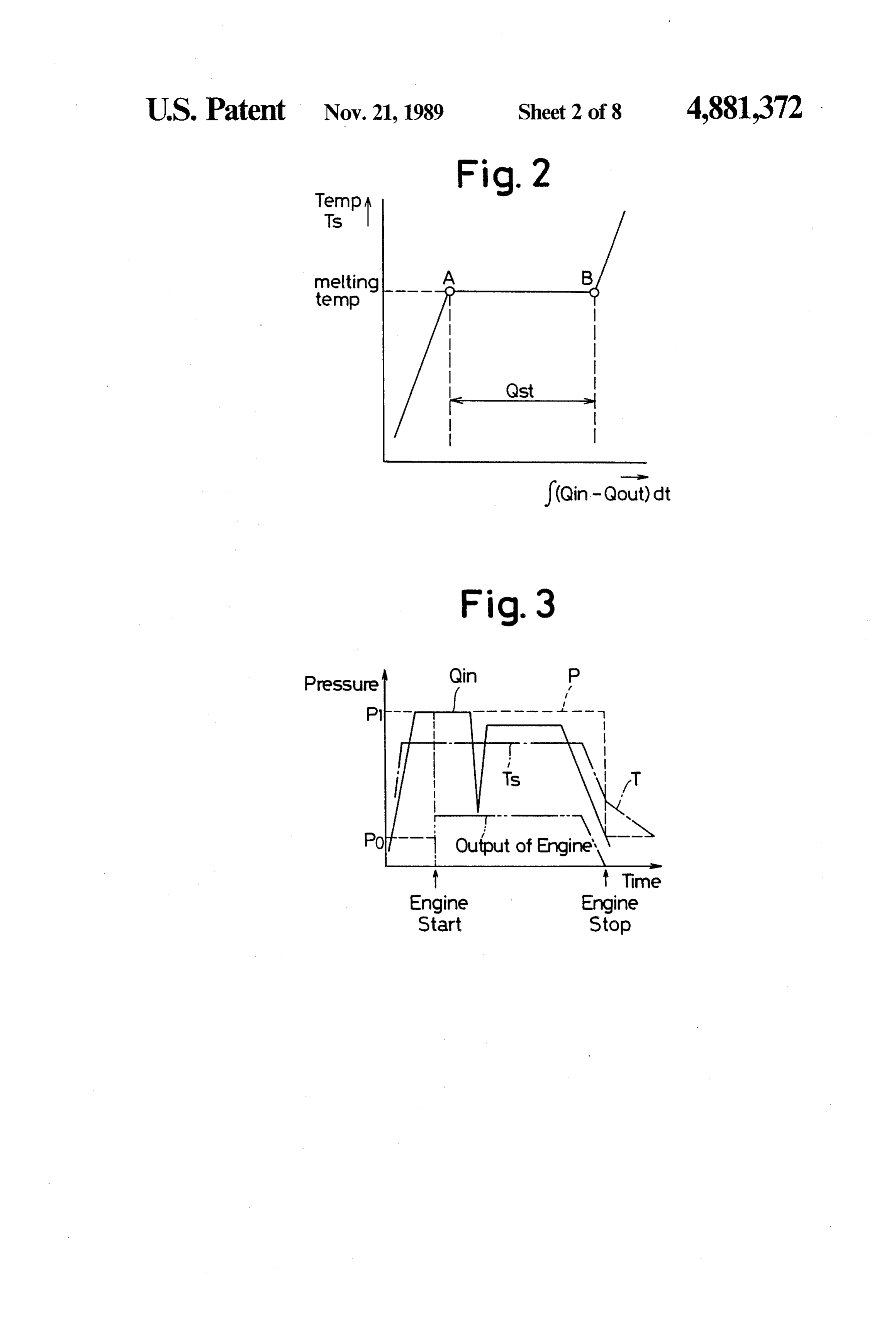
3 shows a time chart during a first operation working space is also connected to the gas reservoir via a maximum-pressure-line which includes a check valve, mode of the engine;
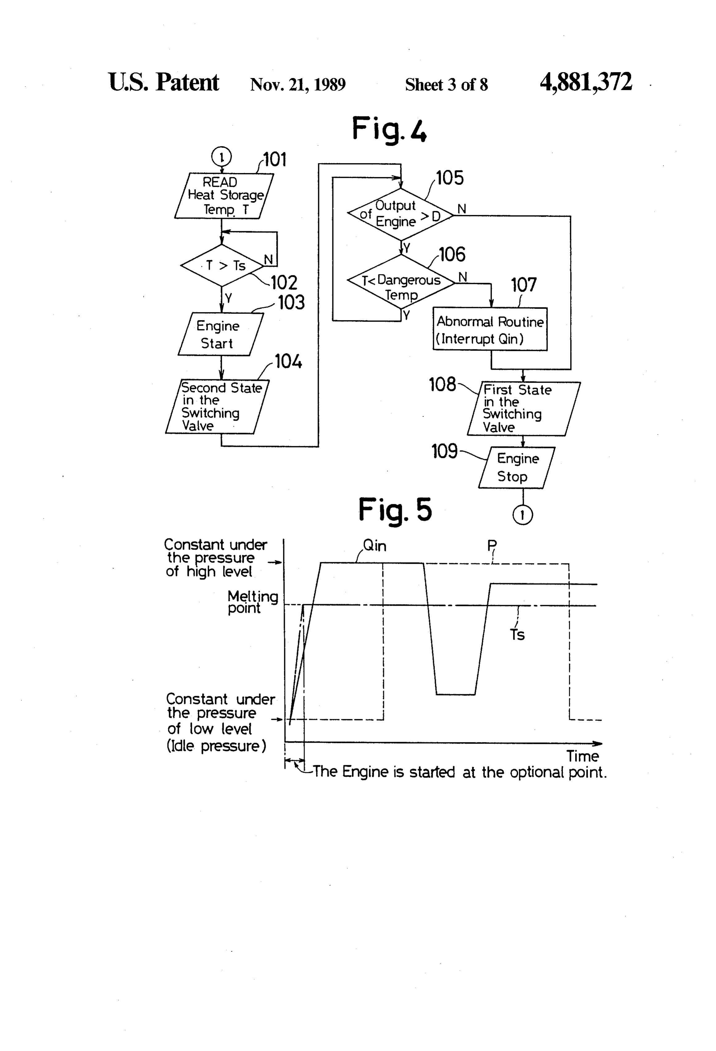
a pressure-decreasing valve and a compressor. As a ofFIG. the 4 shows a flow chart of the first operation mode engine;
result of that construction, when the pressure-increas 35 FIG. 5 shows a time chart during a second operation ing valve is opened, the average pressure is increased mode of the engine;
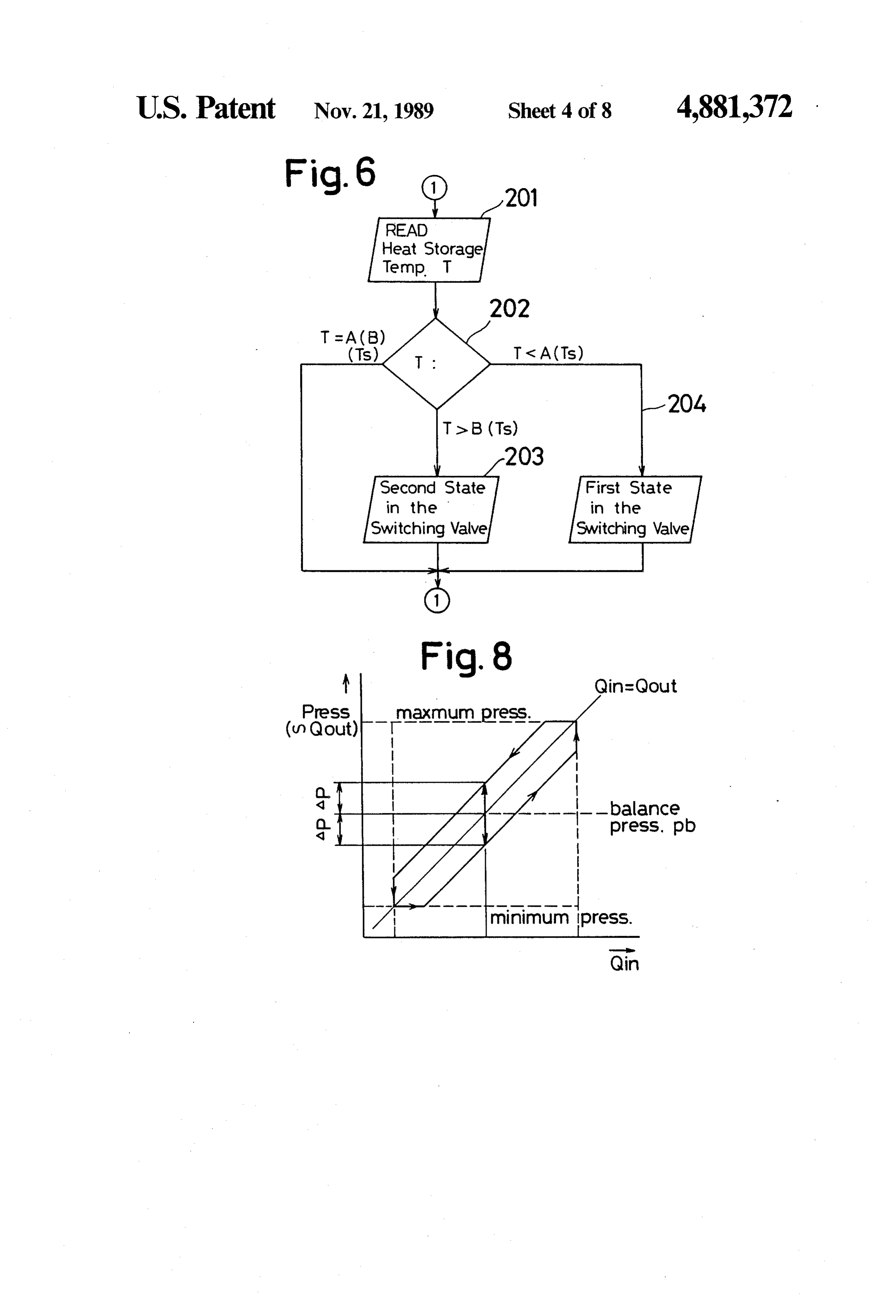
and the engine output is increased. Alternatively, when FIG. 6 shows a flow chart of the second operation the pressure-decreasing valve is opened, the average mode of the engine;
pressure is decreased and the engine output is de FIG. 7 is a cross-sectional view of a Stirling engine creased.
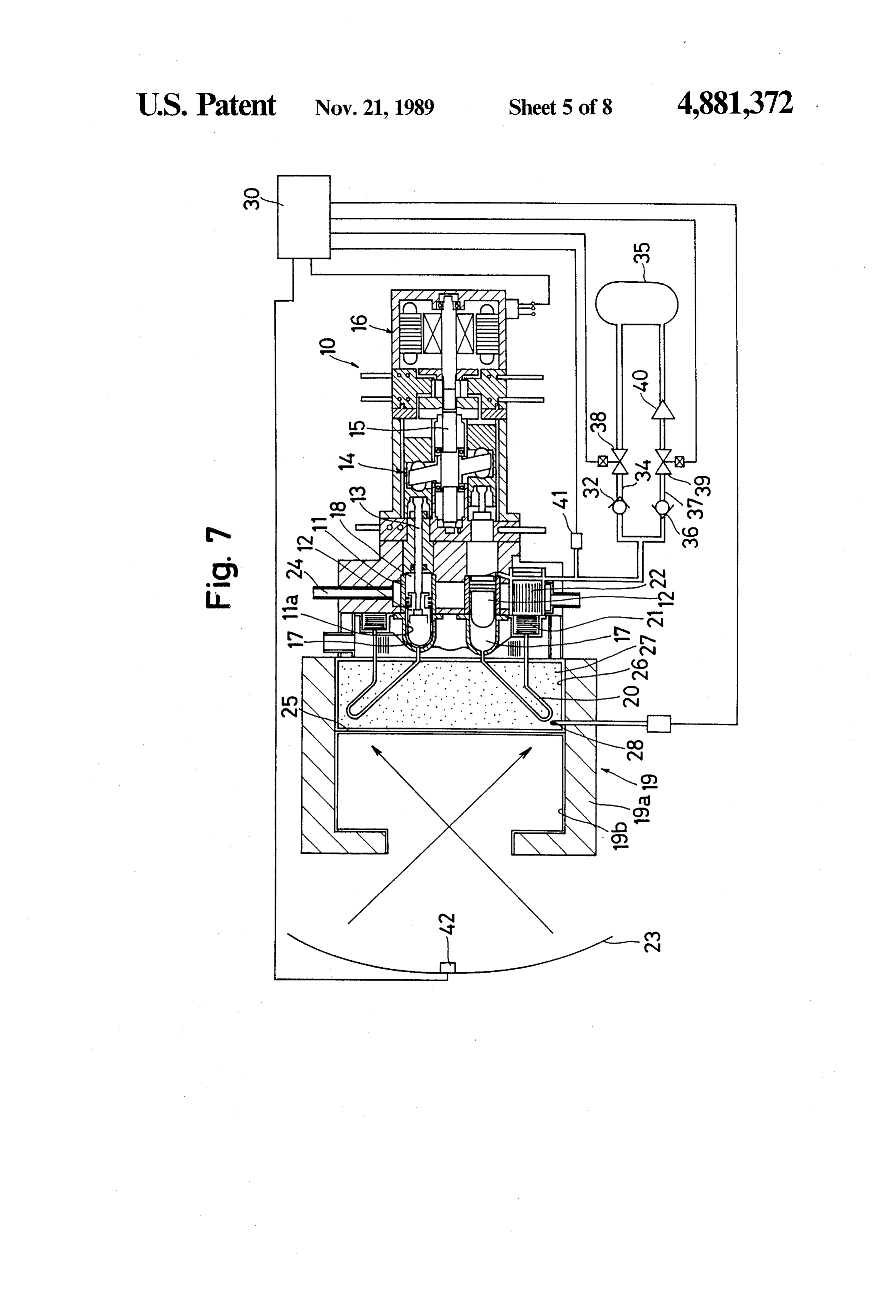
according to another embodiment of the present inven
In the conventional Stirling engine, the engine-output 40 tion;
is controlled as follows:
(1) Since a temperature T of the gas in the pipes is theFIG. 8 is a graph showing the relationship between proportional to an integration value of (Qin-Qout), integration of theofterm temperature the heat-storing material and an (solar radiation energy-quan where Qin and Qout are defined as the quantity of solar 45 tity of heat transfer to tubes) in a third operation mode energy and the quantity of heat-transfer to the gas re of the engine;
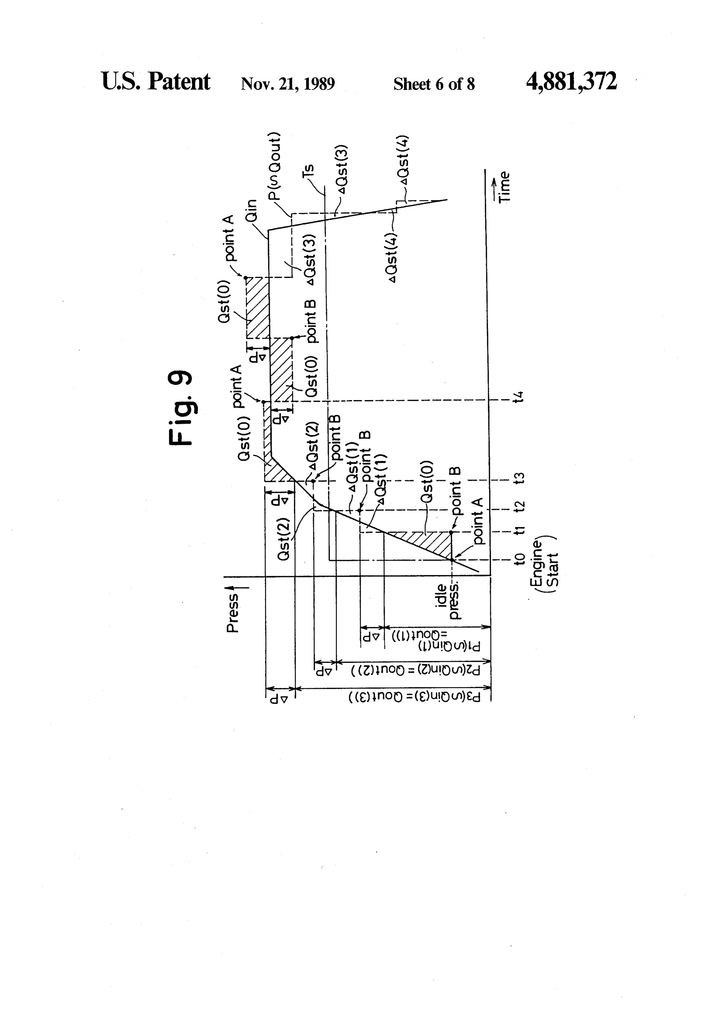
spectively, the integration value should be 0 so that T FIG. 9 shows a time chart during a third operation may be equal to Tset which is dependent upon the abil mode of the engine;
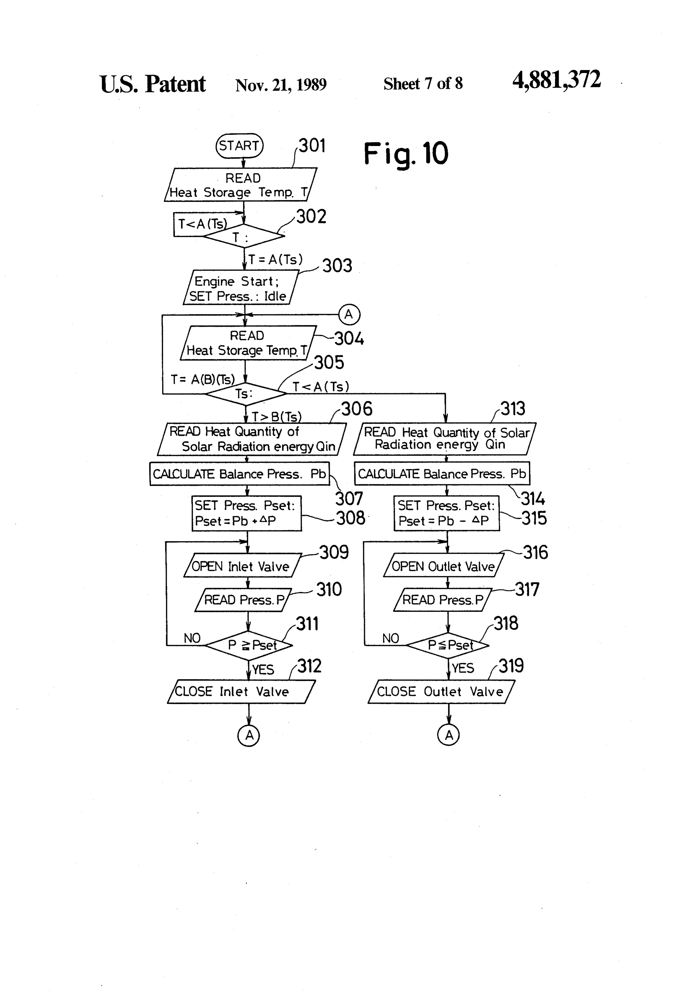
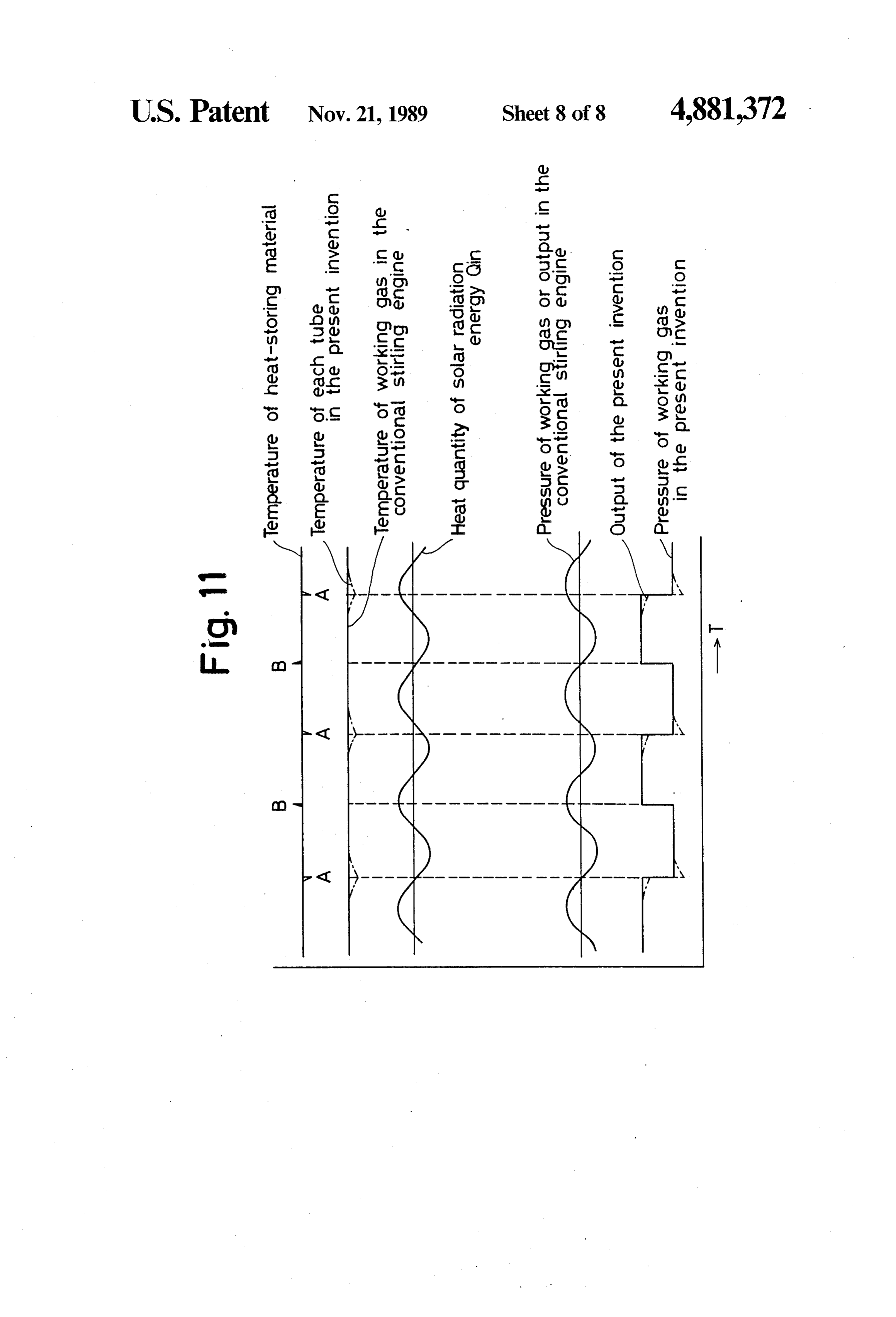
ity and/or rating of the Stirling engine. FIG. 10 shows a flow chart of the third operation (2) Since a pressure P of the gas is proportional to the so mode of the engine; and quantity of heat-transfer to the gas, a linear region cor FIG. 11 is a chart in which characteristics of the responding to Qin=Qout is obtained when P is set to present invention are compared with those of the con Qout for example. Thus, an output region of the Stirling ventional Stirling engine.
engine which depends on the minimum or idle pressure and the maximum pressure, results in the determination 55 DETAILED DESCRIPTION OF THE of the maximum value and the minimum value of Qin. PREFERRED EMBODIMENT Therefore, the operating range of the engine can be Referring now to FIG. 1, a solar-powered Stirling determined. engine 10 includes a housing 11 having four cylinders Consequently, the pressure P can be controlled in 11a (only two of which are shown) located therein. In response to the variation of Qin within the operating 60 each cylinder 11a, a piston 12 is slidably or movably range derived from the above-items (1) and (2), thereby mounted. Each piston 12 is connected via a rod 13 to a keeping the equivalence of Qin and Qout or the equa swash-plate mechanism 14 that serves as an output de tion Qin=Qout. In light of this fact, in the conventional riving mechanism. Two neighboring pistons 12, 12 are Stirling engine, the variable temperature T of the gas in positioned 90 degrees out of phase with respect to each the pipe according to the variation of Qin is detected, 65 other and consequently, as the pistons 12, 12 move, an the difference between T and Tset is calculated, and the output shaft 15 of the swash-plate 14 is rotated and the pressure P is varied according to the resulting differ resulting rotation is transmitted to a dynamo 16 which ence to thereby keep the temperature of the gas at a set generates AC current.
Page 11
In each cylinder 11a, an expansion space 17 and a value of the expression (Qin-Qout) as shown in FIG. 2. compression space 18 are defined across the piston 12. However, it is to be noted that the temperature T of the Spaces 17 and 18 vary in volume due to reciprocal heat-storing material 27 does not change at the melting movement of the piston 12 in such a manner that the point thereof. That is to say, from the beginning of the volume of the expansion space 17 is a maximum when melted condition of the material 27 (point A) to the fully the volume of the compression space 18 is a minimum melted condition (point B) of the material 27, the tem and vice versa. perature T of the material 27 is constant and the latent The expansion space 17 is in fluid communication heat, whose quantity is represented by QSt, is stored in with the compression space 18 via a set of pipes or tubes the heat-storing material 27. Thus, it is desirable that the 20. The pipes 20 extend in an inner portion 19a of the 10 temperature T of the heat-storing material 27 be set heating means 19 and are connected to a regenerator 21 below its melting point in order to prevent the boiling of and a cooler 22, thereby defining a working space. The the material 27 and the breakage of the partition 25. working space is filled with working gas such as helium When vacuum bubbles are generated around the gas, hydrogen gas or the like. Heated working gas tubes 20 during a phase change in the heat-storing mate which moves reciprocally between the expansion space 15 rial 27, the temperature difference between the heat 17. and the compression space 18 brings the pistons 12 storing material 27 and the tubes 20 is increased. Thus, into reciprocal motion, thereby constituting a Stirling measuring the temperature of the tube 20 by a thermal cycle. For heating the working gas, solar radiation sensor is likely to raise the temperature T of the heat energy is employed. Solar radiation energy is collected storing material 27 above its melting point. In recogni by reflector 23 which follows the sun and the resulting 20 tion of that fact, in the present invention, the tempera energy is supplied to the tubes 20 as a high-temperature ture T of the heat-storing material 27 is measured or source through an opening of the housing 19a of the detected by the thermosensor 28 and the melting point heater means 19. It is noted that cooling water flows Ts of the heat-storing material 27 is regarded as an through a conduit 24 so as to be heat-exchanged with optimal operation temperature Tset. For maintaining Ts the working gas in the cooler 21 and the tubes 20 are 25 at a value, the pressure of the working gas is controlled arranged in the radial direction. through operation of a pressure regulating means that Within the inner portion 19b of the housing 19a, a includes the valves 31, 32 and 36.
transparent partition 25 with good thermal conductiv In FIG. 4, when the Stirling engine reaches the ity, good thermal resistance and good corrosion resis steady operating condition, the detected temperature T tance is disposed, thereby defining a closed space 26 30 of the heat-storing material 27 by the thermosensor 28 is within which the tubes 20 are located. Examples of the transmitted as signals to the control unit 30 in step 101. heat storing material 27 which can store heat are NaCl, In step 102, the temperature T is compared to Ts to Li2CO3, MgCl2, etc., which store latent heat. It is desir determine whether the detected temperature T is able that the heat-storing material 27 possess good ther greater than the temperature Ts. mal conductivity, good thermal resistance and good 35 In step 102, if the answer is no and the detected tem corrosion resistance. perature T of the heat-storing material 27 is less than Ts, Also, within the closed space 26, a temperature sen step 101 is again executed. If the answer in step 102 is sor 28 in the form of thermocouple is disposed for de yes, step 103 is then executed. It should be noted that tecting the temperature of the heat-storing material 27. the switching valve 31 is held at one position before the The detected temperature is transmitted in the form of 40 temperature T of the heat-storing material 27 is raised signals to a control unit 30. up to the melting point Ts, thereby maintaining the . The working space is in fluid communication with a pressure of the working space at the idle pressure. Thus, gas reservoir 35 via a minimum-cycle-pressure line 34 the temperature T of the heat-storing material 27 begins which includes a check-valve 32 and a switching valve to raise abruptly. At the time that the temperature T of 31 and via a maximum-cycle-pressure line 37 which 45 the heat-storing material 27 reaches the melting point includes a check-valve 36 and the switching valve 31. Ts, the temperature T is located at point A on the graph The switching valve 31 is an electromagnetic valve of shown in FIG. 2 and the pressure P of the working gas the 3-port/2-position type and is under the control of is kept at the idle pressure. Thus, any increase in Qin is the control unit 30 so that change from one state to the consumed for melting the heat-storing material 27 and other may take place according to the signals from the 50 the temperature of the heat-storing material 27 remains temperature sensor 28. Under one state of the switching COIStant.
valve 31, the gas reservoir 35 is in fluid communication In step 103, a starter (not shown) which can be re with the maximum-cycle-pressure line 37 and is out of placed by the AC dynamo 16 drives the shaft 15 of the fluid communication with the minimum-cycle-pressure swash-plate mechanism which results in the pistons 12 line 34. When the switching valve is in the other state, 55 being brought into reciprocal movement. Simulta the gas reservoir 35 is in fluid communication with the neously, the solar radiation energy Qin heats the tubes minimum-cycle-pressure line 34 and is out of fluid com 20 through the heat-storing material 27, thereby bring munication with the maximum-cycle-pressure line 37. It ing the engine 10 into independent operation. Then, the is noted that the pressure of the gas which is stored in switching valve 31 is switched into the other state by the gas reservoir 35 is equal to the maximum pressure of the control unit 30 in step 104, thereby raising the pres the working gas in the working space. sure P in the working space up to the maximum value. Operation of the above-described Stirling engine 10 Thus, the quantity of heat transfer to the tubes 20 is will be described hereinafter with reference to FIG. 3 maximized and the output of the engine 10 begins to showing a time chart and FIG. 4 showing a flowchart. increase. Thereafter, despite any decrease in solar radia The solar radiation energy and the quantity of heat 65 tion energy Qin, Qout is kept at a particular value by transfer to the tubes 20 are defined by symbols Qin and consuming the heat stored in the material 27. During Qout respectively, and the temperature T of the heat this process, there is no need to control the pressure storing material 27 is proportional to the integration regulating means quickly and precisely. Thus, stable
Page 12
output can be obtained from the engine 10. Upon fur the gas reservoir 35, there is interposed a compressor ther decrement of Qin after consumption of Qst, the 40. In a conduit that connects each working space and engine 10 stops. That is to say, if the output of the en the valves 32 and 36, there is interposed a pressure gine 10 is zero in step 105, the switching valve 31 is sensor 41. The pressure that is detected by the sensor 41 switched back to the one state in step 108, and the en is transmitted as a signal to the control unit 30. On the gine 10 is stopped in step 109. reflector 23, there is provided a device 42 for measuring If the output of the engine is not zero in step 105, a the heat quantity of solar radiation energy Qin and the check is performed whether the temperature T of the measured quantity is transmitted as a signal to the con heat-storing material 27 is below a dangerous tempera trol unit 30, d ture. If the temperature T is below a dangerous amount, 10 In FIG. 9, before the temperature T of the heat-stor step 105 is performed again. If the temperature T is not ing material 27 reaches the point B, the pressure P of the below a dangerous temperature, an abnormal routine is working space is kept at an idle pressure. As soon as the performed in step 108 so as to close the opening 19c for temperature T of the heat-storing material 27 reaches interrupting solar radiation, the switching valve 31 is the point B, the pressure P of the working space is set by switched back to the one state in step 108, and the en 15 adding a value AP to the pressure corresponding to gine 10 is stopped in step 109. Qin=Qout. Since the quantity of heat transfer to the FIG. 5 shows a time chart and FIG. 6 shows a flow tubes 20 is represented by Qout--Qst(1), the supply of chart according to a second mode of operation of the AQst(1) from Qst in the material 27 brings the tempera present invention. The construction of the engine ture T towards point A from point B. Since Qin is in whose time chart is depicted in FIG. 5 and whose flow 20 creased, Qst(l) is returned to Qin and the temperature T chart is depicted in FIG. 6 is the same as shown in FIG. of the material 27 is again transferred to point B. At this 1. time, the pressure P of the working space is set by add In this operation mode, the pressure of the working ing AP to the pressure corresponding to Qin. Hereinaf gas in the working space is controlled in 2-stages, a ter, AP is added whenever temperature T of the mate minimum operating pressure (Qin-min) and a maximum 25 rial 27 is transferred to the point B. operation pressure (Qin-max). When Qin no longer increases, the quantity (Qout In FIG. 5, the temperature T of the heat-storing ma --Qst(0)), which is derived from the working gas upon terial 27 raises as the solar radiation energy Qin in increasing the pressure by AP, becomes larger than Qin creases, and the switching valve 31 is held at one state to be supplied to the material 27. The temperature of the thereof before the temperature Treaches point B. Thus, 30 heat storing material is not able to return to point B and the pressure P in the working space is held at a mini reaches point A. The pressure is then decreased by AP mum or idle pressure. As soon as the temperature T of and thus, an amount of heat represented by the heat storing material 27 reaches point B, wherein (Qin-Qst(O)) is stored in the material 27. When that the temperature T exceeds the melting point Ts, the stored quantity becomes Qst(O), the temperature T of switching valve 31 is changed to the other state thereof, 35 the material 27 once again reaches the point B and the thereby maximizing pressure P in the working space. pressure P is changed by adding AP. Hereinafter, when Thus, Qout is maximized. Thereafter, when Qst is con Qin is constant, the pressure P draws an endless loop as sumed as Qin is decreased or as the temperature T of the shown in FIG. 8.
heat-storing material 27 is returned to the point A at Next, when Qin decreases, the temperature T of the which the temperature T is below the melting point Ts, 40 heat-storing material 27 cannot return to point B and the Switching valve 31 is changed back to the one state reaches point A. In this case, the pressure P of the thereof, thereby minimizing the pressure P in the work working gas is decreased by AP. If the temperature T of ing space. This results in the decrease of Qout and the the heat-storing material 27 cannot return to point B increase of the heat in the material 27. When the tem despite that operation, further decrement of AP is per perature T of the heat-storing material 27 reaches the 45 formed.
point B again, the switching valve 31 is changed back to The foregoing operation mode is detailed in the flow the other state thereof, thereby maximizing the pressure chart shown in FIG. 10.
P in the working space. While this invention has been illustrated and de The foregoing operation mode is detailed in the flow scribed in accordance with preferred embodiments, it is chart shown in FIG. 6. That is to say, the temperature 50 recognized that variations and changes may be made T of the heat-storing material 27 is transmitted to the herein without departing from the invention as set forth control unit 30 in step 201, and the temperature T of the in the claims.
heat-storing material 27 is compared to the melting What is claimed is:
point Ts thereof in step 202. If T is equal to Ts, step 201 1. A Stirling engine comprising; is executed again. If T is greater than Ts, the switching 55 heater means for collecting solar radiation energy, valve 31 is switched to the other state thereof in step a heater tube disposed in said heater means and con 203. If T is less than Ts, the switching valve 31 is necting an expansion space and a compression switched to the one state thereof in step 204. Conse space through a regenerator and a cooler; quently, in this operation mode, the frequency of the a transparent partition disposed in said heater means Switching operation is less due to utilization of the 60 and defining a closed space within which said stored heat in the material 27. heater tube is located;
In FIG. 7, there is illustrated a second embodiment of a heat storage material positioned in said closed the present invention. The features of this embodiment Space;
are as follows. A pressure-increasing valve 38 and a temperature detecting means for detecting a tempera pressure-decreasing valve 39 are disposed in the maxi 65 ture of said heat storage material; mum pressure line 34 and the minimum pressure line 37 pressure regulating means for regulating a pressure of respectively, and are operable independently of each a working gas in a working space from said expan other. Between the pressure-decreasing valve 39 and sion space to said compression space; and
Page 13
control means for controlling said pressure regulating heat quantity of solar radiation energy and pressure means in response to a signal from said temperature detecting means for detecting the pressure of said work detecting means. ing gas in said working space, wherein said control 2. A Stirling engine as recited in claim 1, wherein said means predetermines a target pressure value in response pressure regulating means includes a supply source for to said signal from said temperature detecting means supplying said working gas, said supply source being and a signal from said measuring means and causes said connected to said working space through a minimum pressure regulating means to operate so as to change the cycle-pressure line having a one-way valve permitting a pressure in said working pressure to said target pressure flow of working gas into said working space and value.
through a maximum-cycle-pressure line having a one O 6. A Stirling engine as recited in claim 5, wherein said way valve preventing a flow of working gas into said pressure regulating means includes a supply source for working space, and a switching valve interposed be supplying said working gas, said supply source being tween said supplying source and both of said lines, said connected to said working space through a minimum switching valve being selectively switched by said con cycle-pressure line having a one-way valve permitting a trol means between a first state in which communica 5 flow of working gas into said working space and tion between said supplying source and said maximum through a maximum-cycle-pressure line having a one cycle-pressure line is permitted and communication way valve preventing a flow of working gas into said between said supplying source and said minimum-cycle working space, and an increasing pressure valve dis pressure line is prevented and a second state in which posed in said minimum-cycle-pressure line and a de communication between said supplying source and said 20 creasing pressure valve disposed in said maximum minimum-cycle-pressure line is permitted and commu cycle-pressure line.
nication between said supplying source and said max 7. A Stirling engine as recited in claim 6, wherein said imum-cycle-pressure line is prevented. control means compares a detected temperature of said 3. A Stirling engine as recited in claim 2, wherein said temperature detecting means to said melting point of switch valve maintains said first state until the tempera 25 said heat storage material and calculates an ideal pres ture of said heat storage material is more than a melting sure value of said working gas in response to the radia point of said heat storage material, said switch valve tion heat quantity measured by said measuring means, being switched to said second state by said control and said control means controls the opening and closing means when the temperature of said heat storage mate of said increasing pressure valve and said decreasing rial is more than a melting point of said heat storage 30 pressure valve so as to raise the pressure in said working material. - space up to a value which is higher than the ideal pres 4. A Stirling engine as recited in claim 2, wherein said sure by a predetermined value when the temperature of switch valve maintains said first state until the tempera said heat storage material is higher than said melting ture of said heat storage material is more than a melting point and controls the opening and closing of said in point of said heat storage material, and said switch 35 creasing pressure valve and said decreasing pressure valve is switched to said second state by said control valve so as to lower the pressure in said working space means when the temperature of said heat storage mate to a value which is lower than the ideal pressure by a rial is more than a melting point of said heat storage predetermined value when the temperature of said heat material and is switched to said first step by said control storage material is lower than said melting point. means when the temperature of said heat storage mate 40 8. A Stirling engine as recited in claim 7, wherein said rial is less than a melting point of said heat storage mate control means causes said increasing pressure valve and rial, whereby the temperature of said heat storage mate said decreasing pressure valve o operate so as to main rial is maintained at said melting point. tain the temperature of said heat storage material at said 5. A Stirling engine as recited in claim 1, further melting point.
comprising a measuring means for measuring radiation 45 st k is k k
Provenance
- Collection
- Cited prior art
- Original PDF
- patentimages.storage.googleapis.com →
- Filed
- 1989-02-28
- Pages
- 13
- Method
- pdftotext (the PDF's own text layer) + pdftoppm 300dpi page scans
- Source
- Google Patents bibliographic record
- Granted
- 1989-11-21
- Inventors
- Yoshihiro Naito; Aisin Seiki Co Ltd
- Transcribed from
- patentimages.storage.googleapis.com →