patent · US11092744B2
Three-dimensional surface display device disposed on a vehicle and vehicle display device having a three-dimensional surface display device
17 August 2021
Page 1 — bibliographic record
( 12) United States Patent ( 10) Patent No.: US 11,092,744 B2 Sato et al . (45 ) Date of Patent : Aug. 17, 2021 ( 54 ) THREE -DIMENSIONAL SURFACE DISPLAY ( 52 ) U.S. CI .
DEVICE DISPOSED ON A VEHICLE AND CPC G02B 6/262 ( 2013.01 ) ; B60Q 1/50 VEHICLE DISPLAY DEVICE HAVING A ( 2013.01 ); B60Q 2400/00 ( 2013.01 ) THREE -DIMENSIONAL SURFACE DISPLAY ( 58 ) Field of Classification Search DEVICE CPC F21S 43/14 ; F21S 43/15 ; F21S 43/237 ;
( 71 ) Applicant: KOITO MANUFACTURING CO . , (Continued ) LTD ., Tokyo ( JP )
( 72 ) Inventors: Ryuho Sato , Shizuoka (JP ) ; Akinori U.S. PATENT DOCUMENTS Matsumoto, Shizuoka ( JP ); Haruhiko
Iyoda , Shizuoka ( JP) ; Hiroya Koizumi , 3,590,248 A * 6/1971 Chatterton , Jr. GO2B 6/4249 Shizuoka (JP) 398/91
( 73 ) Assignee : KOITO MANUFACTURING CO . , 355/1 LTD ., Tokyo ( JP ) ( Continued ) ( * ) Notice: Subject to any disclaimer, the term of this FOREIGN PATENT DOCUMENTS patent is extended or adjusted under 35 JP 2001-043493 A 2/2001
U.S.C. 154 ( b ) by 10 days. JP 2014-229510 A 12/2014 (21 ) Appl. No .: 16 /500,680 ( Continued ) Apr. 4 , 2018 OTHER PUBLICATIONS
International Search Report issued in PCT/JP2018/014465 dated (86) PCT No .: PCT / JP2018 /014465 Jun . 19 , 2018 ( 5 pages ) . $ 371 ( c ) (1 ), (Continued )
Primary Examiner — Chad H Smith ( 87 ) PCT Pub . No .: WO2018 /186450 (74 ) Attorney, Agent, or Firm -Osha Bergman Watanabe & Burton LLP
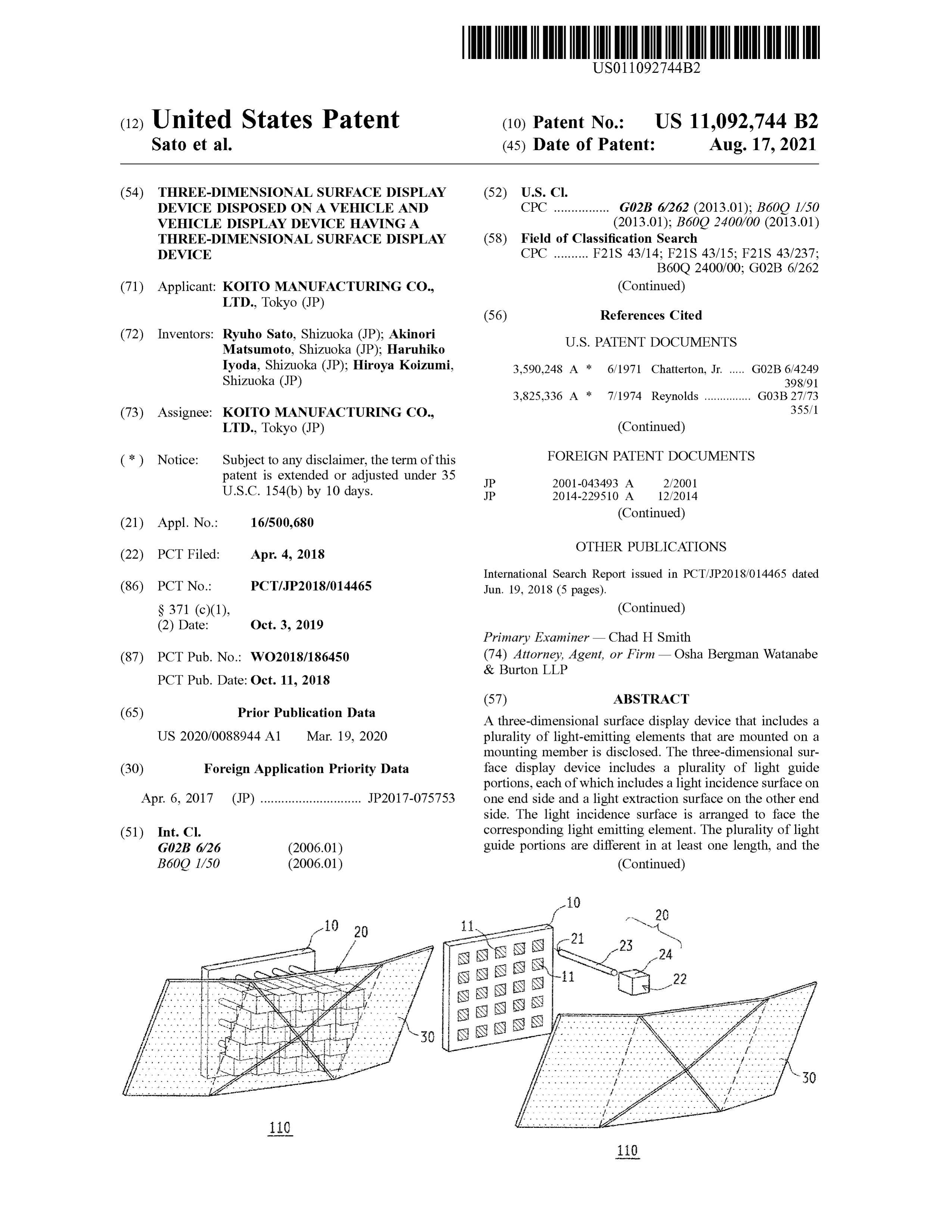
A three - dimensional surface display device that includes a
US 2020/0088944 A1 Mar. 19 , 2020 plurality of light - emitting elements that are mounted on a mounting member is disclosed. The three - dimensional sur ( 30 ) Foreign Application Priority Data face display device includes a plurality of light guide portions, each of which includes a light incidence surface on
Apr. 6 , 2017 (JP ) JP2017-075753 one end side and a light extraction surface on the other end side . The light incidence surface is arranged to face the ( 51 ) Int . Ci . corresponding light emitting element. The plurality of light GO2B 6/26 ( 2006.01 ) guide portions are different in at least one length , and the B60Q 1/50 ( 2006.01 ) (Continued )
Page 2
light extraction surfaces are arranged three -dimensionally 6,377,739 B1 * 4/2002 Richardson B41J 2/46 adjacent to each other. 6,571,043 B1 * 5/2003 Lowry
5 Claims , 8 Drawing Sheets 345/40
( 58 ) Field of Classification Search 362/601 USPC 385/116 2003/0103744 A1 * 6/2003 Koyama HO4N 5/23238 See application file for complete search history. 385/116 2003/0235380 A1 * 12/2003 Thayer GO2B 6/06
( 56 ) References Cited 2010/0188742 A1 * 7/2010 Chen GO2B 21/0064
2010/0253949 A1 * 10/2010 Adler A61B 5/0084 3,830,667 A * 8/1974 Carpenter CO3B 37/15 356/479 156/155 2015/0362144 A1 * 12/2015 Bauer F21S 41/255 3,832,488 A 8/1974 Fahey B41J 2/46 362/511 178/15 2015/0369447 A1 * 12/2015 Lanchava GO2B 6/0006 4,208,363 A * 6/1980 Yevick B29D 11/00278 362/583 264 / 1.24 2016/0116662 A1 * 4/2016 Sato GO2B 6/0051 4,275,950 A 6/1981 Meyer GO2B 3/00 362/520 126/698 2017/0280970 A1 * 10/2017 Sartor A61B 1/0684 4,311,999 A 1/1982 Upton GO2B 27/017 2018/0289257 A1 * 10/2018 Ikegami A61B 3/1225 340 / 407.1 2020/0114580 A1 * 4/2020 Hunze B29C 64/153
5,862,278 A * 1/1999 Brauch B23K 26/0604 Written Opinion of the International Searching Authority issued in 385/119 PCT/JP2018/014465 dated Jun . 19 , 2018 ( 5 pages ).
Page 3
Drawing sheet — no readable text.
Page 4
Drawing sheet — no readable text.
Page 5
Drawing sheet — no readable text.
Page 6
Drawing sheet — no readable text.
Page 7
Drawing sheet — no readable text.
Page 8
Drawing sheet — no readable text.
Page 9
Drawing sheet — no readable text.
Page 10
Drawing sheet — no readable text.
Page 11
THREE - DIMENSIONAL SURFACE DISPLAY side and a light extraction surface on the other end side , and DEVICE DISPOSED ON A VEHICLE AND is arranged to face the corresponding light emitting element, VEHICLE DISPLAY DEVICE HAVING A wherein the plurality of light guide portions are different in THREE - DIMENSIONAL SURFACE DISPLAY at least one length , and the light extraction surfaces are 5 arranged three - dimensionally adjacent to each other.
DEVICE
In the three - dimensional surface display device of the
TECHNICAL FIELD present invention, the plurality of light guide portions hav ing the light incidence surfaces facing the light emitting
The present invention relates to a three - dimensional sur 10 elements are provided, and the light extraction surfaces are face display device and a vehicle display device . arranged three - dimensionally adjacent to each other with
BACKGROUND
different lengths of the light guide portions. Therefore , according to the above configuration , it is possible to obtain
Conventionally, in a normal vehicle operated by a driver, a sense of unity with a vehicle while displaying an image astop lamp,a taillight,a direction indicator, or thelike are 15 corresponding to a three. -dimensional curved surface shape with a simple structure manually operated in order to indicate a traveling state of the In one or more embodiments of the invention , the light vehicle to other vehicles, a pedestrian, or the like around the guide portion includes an optical fiber at least a part. vehicle . In recent years , an automatic driving technique of a In one or more embodiments of the invention, a light vehicle has been remarkably developed, and an environment in which a situation in which various operations of the 20 expanding portion configured to expand a diameter of light vehicle are substituted by an information processing means emitted from a light emitting end surface of the optical fiber provided in the vehicle is being established . In the automatic to substantially the entire area of the light extraction surface driving technique, since the information processing means is further included .
operates the vehicle based on detection results of various In one or more embodiments of the invention , the light sensors , complex information can be instantaneously pro- 25 guide portion includes a translucent columnar member, and cessed . Therefore, a traveling state or the like can be one end surface of the columnar member is the light extrac indicated to other vehicles , a pedestrian, or the like using an tion surface .
image display device . Patent Document 1 proposes a tech- In one or more embodiments of the invention , the light nique of providing an image display device in a vehicle and extraction surface is formed with a light scattering structure displaying various information on the outside of the vehicle . 30 for scattering and extracting light. PATENT DOCUMENT In one or more embodiments of the invention, a three dimensional shaped outer panel formed of a translucent
Patent Document 1 : JP -A - 2001-043493 material is further included, and the light extraction surfaces 35 are arranged along an inner surface of the outer panel .
SUMMARY OF INVENTION According to embodiments of the invention , there is provided a vehicle display device including any one of the
However, in the related art of Patent Document 1 , it is three - dimensional surface display devices described above , necessary to separately attach the image display device to wherein the outer panel is arranged on an exterior portion of the vehicle, and a position at which the image display device 40 a vehicle.
can be attached and a size of the image display device are According to the present invention, it is possible to restricted to a shape of the vehicle. In addition, in order to provide the three - dimensional surface display device and the attach an existing image display device, a flat plate -shaped vehicle display device capable of obtaining the sense of member is attached to an outer periphery of the vehicle, unity with the vehicle while displaying the image corre which significantly impairs a design of the vehicle. 45 sponding to the three - dimensional curved surface shape with In a case of using an image display device having a curved the simple structure .
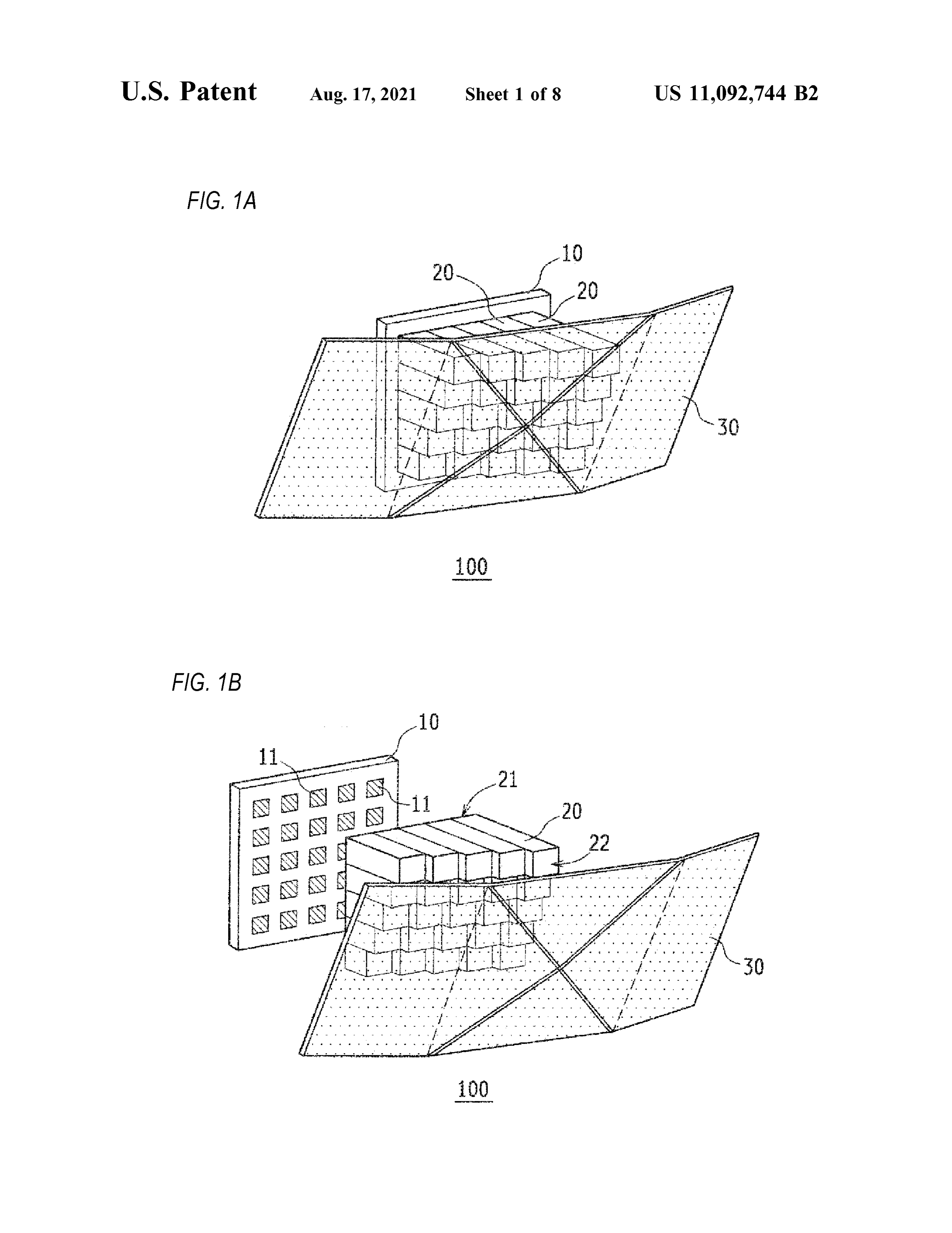
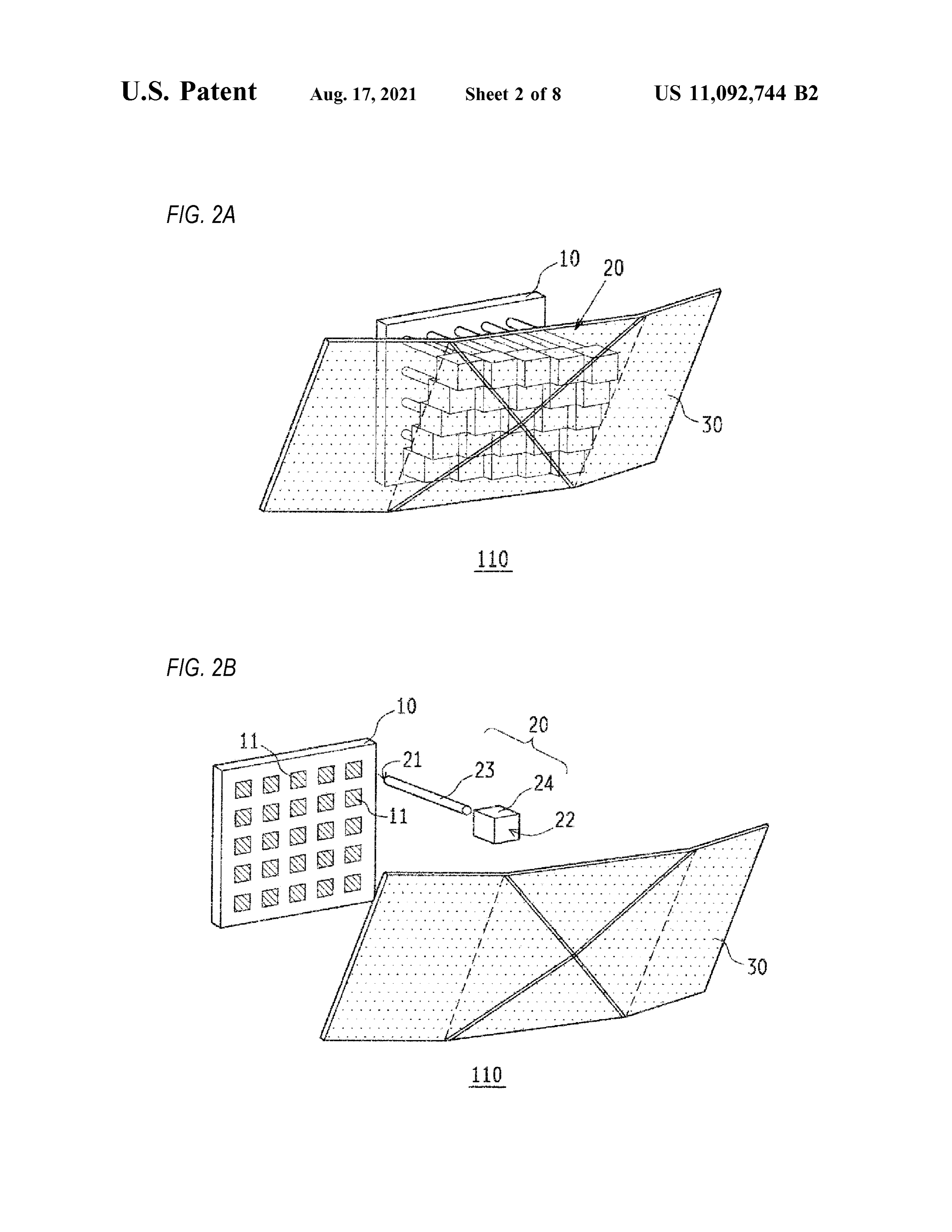
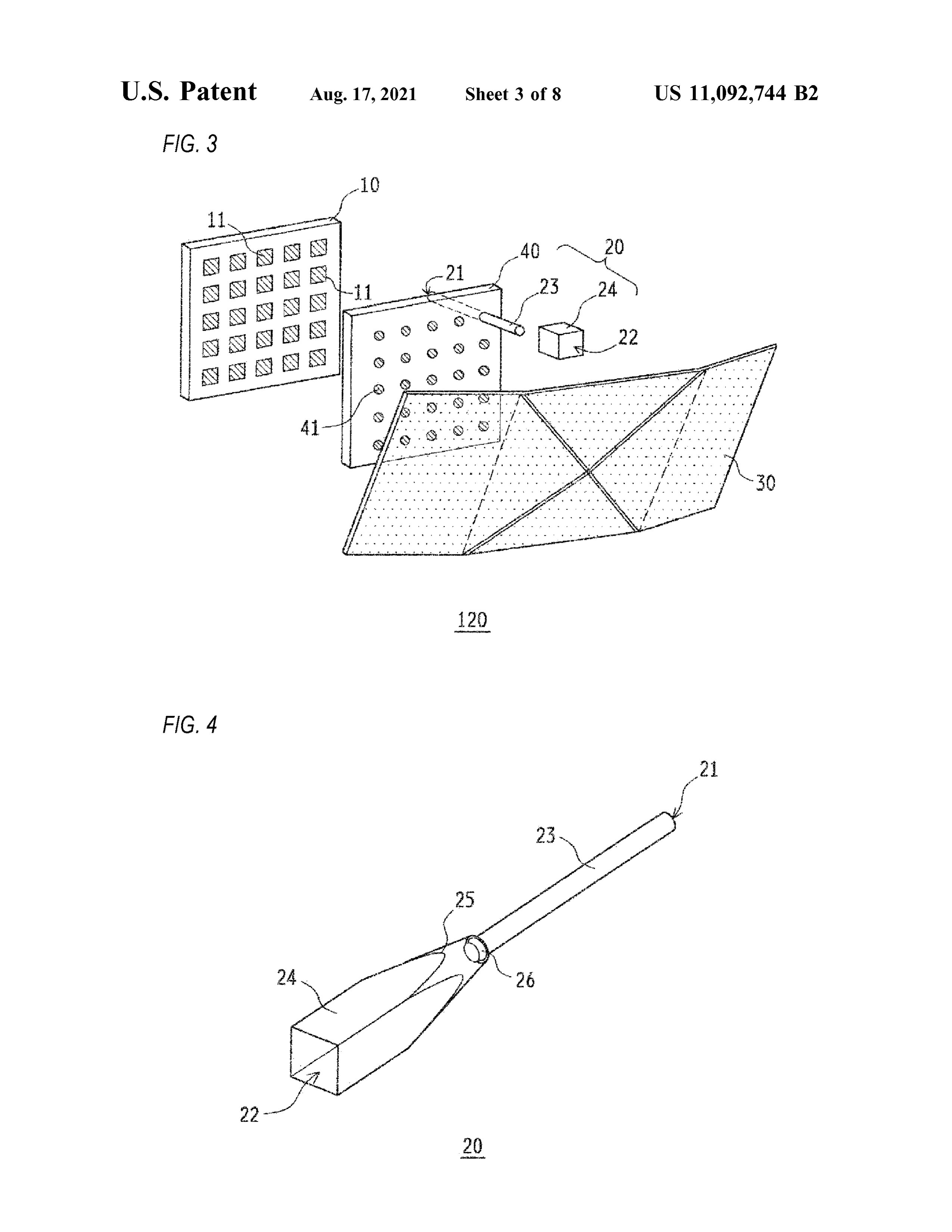
surface shape, since it is necessary to individually design a shape according to the design of the vehicle and an attaching BRIEF DESCRIPTION OF THE DRAWINGS position at the vehicle, a versatility is poor and a manufac turing process is complicated . In addition, even if the curved 50 FIG . 1A is a schematic perspective view showing a surface shape of the image display device is designed three - dimensional surface display device 100 according to individually, it is not possible to obtain a sense of unity one or more embodiments of the present invention . between the vehicle and the image display device by attach- FIG . 1B is an exploded perspective view showing the ing to the outer periphery of the vehicle, so that the design three - dimensional surface display device 100 according to is impaired . 55 one or more embodiments of the present invention . The present invention has been made in view of the above FIG . 2A is a schematic perspective view showing a conventional problems, and an object thereof is to provide a three - dimensional surface display device 110 according to three - dimensional surface display device and a vehicle dis- one or more embodiments of the present invention . play device capable of obtaining a sense of unity with a FIG . 2B is an exploded perspective view showing the vehicle while displaying an image corresponding to a three- 60 three - dimensional surface display device 110 according to dimensional curved surface shape with a simple structure . one or more embodiments of the present invention . In order to solve the above problems , according to FIG . 3 is an exploded perspective view showing a three embodiments of the present invention , there is provided a dimensional surface display device 120 according to one or three - dimensional surface display device including a plural- more embodiments of the present invention . ity of light emitting elements which are mounted on a 65 FIG . 4 is a schematic perspective view showing a light mounting member; and a plurality of light guide portions, guide portion 20 in one or more embodiments of the present each of which includes a light incidence surface on one end invention .
Page 12
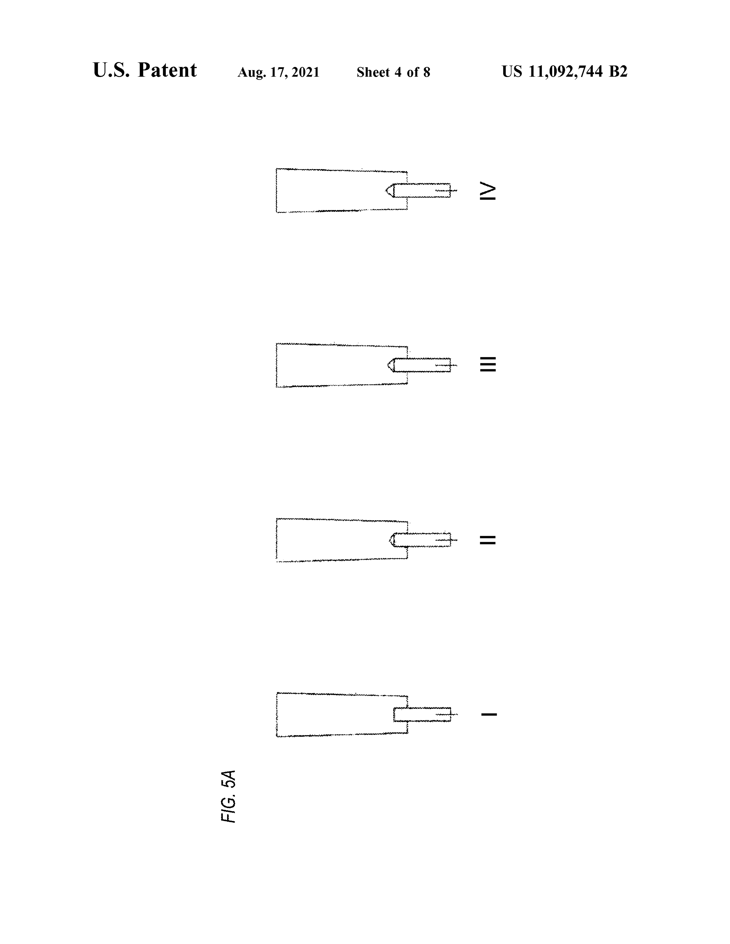
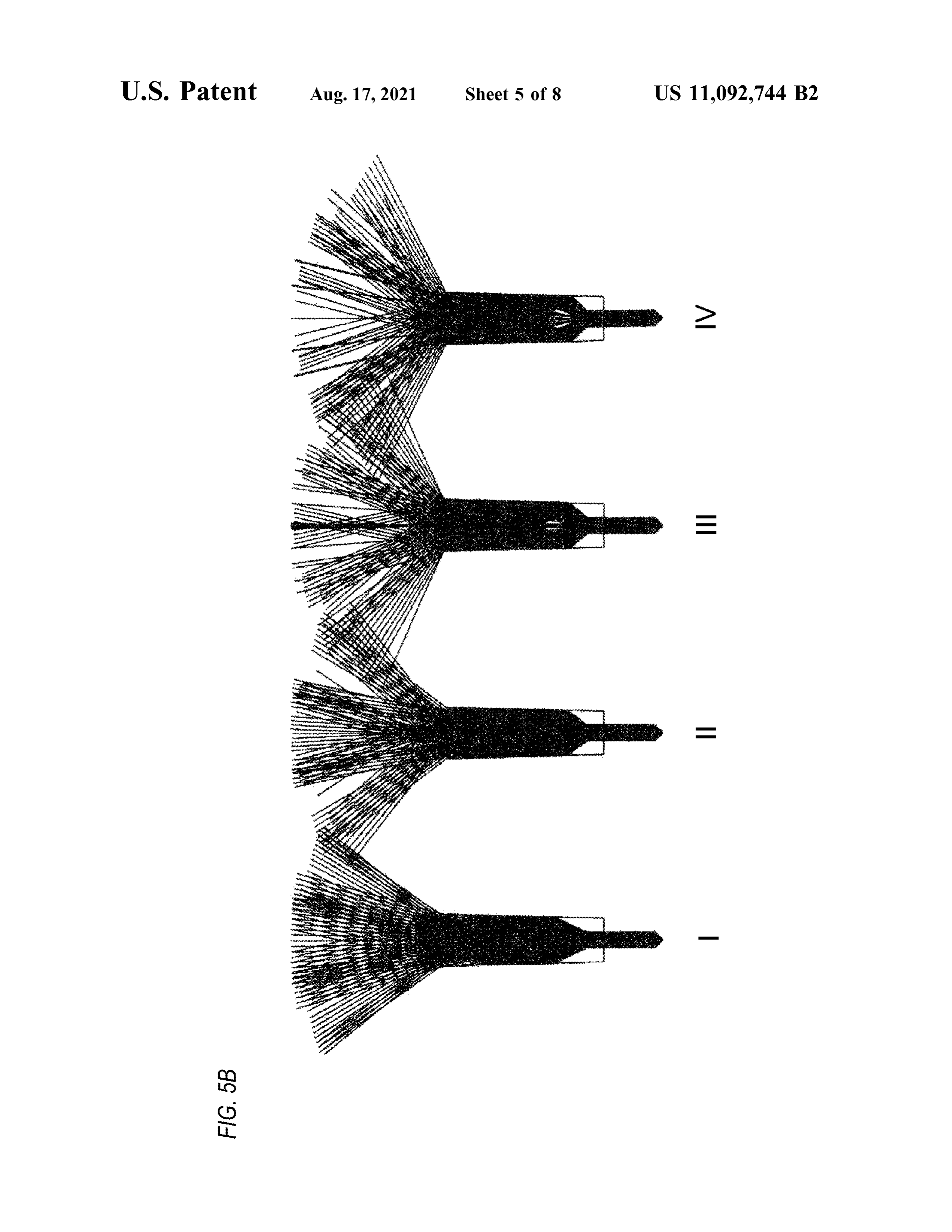
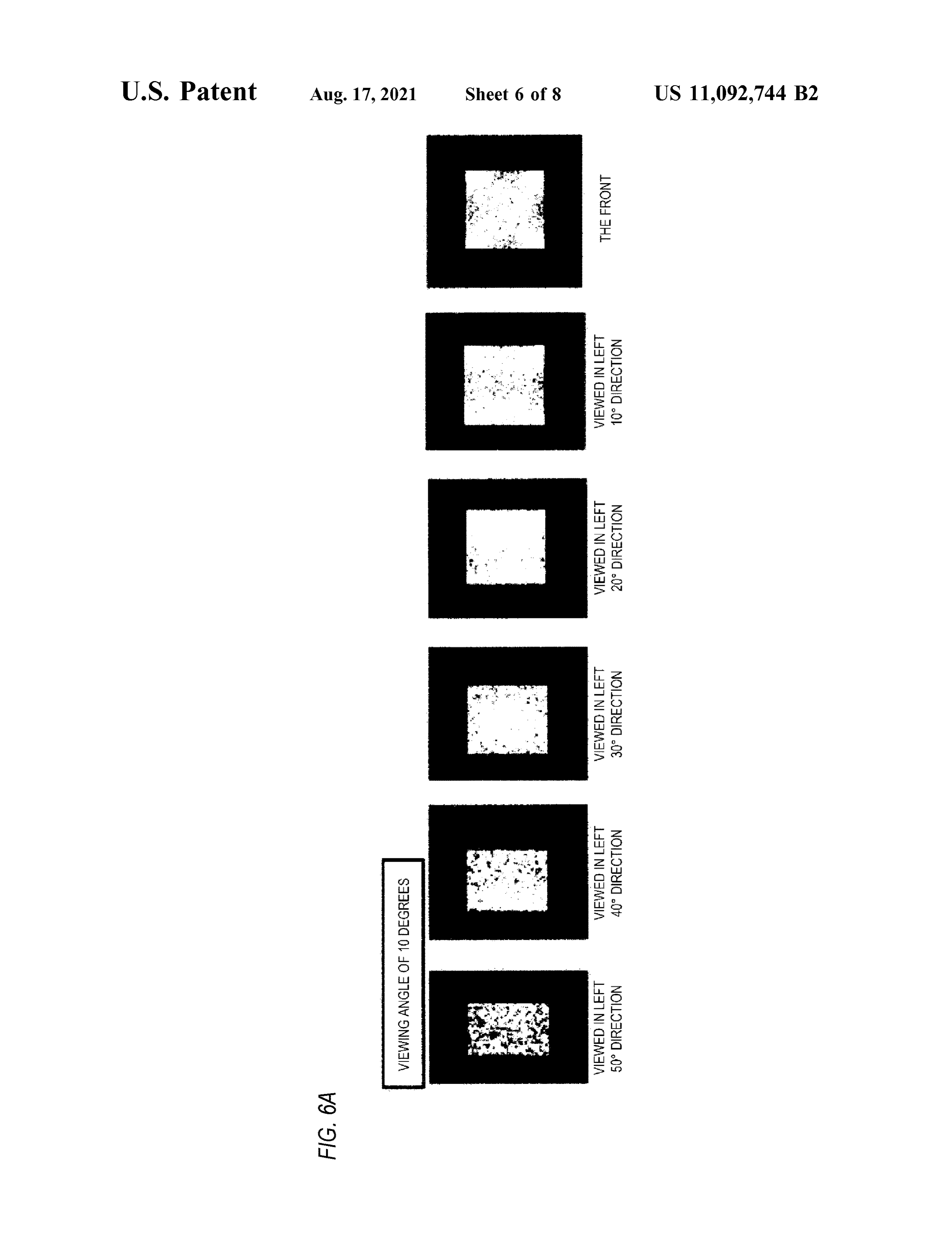
FIG . 5A is a schematic sectional view showing shapes of Each of the light guide portions 20 is a substantially an optical fiber 23 , a light expanding portion 25 , and a fiber columnar member made of a material which transmits light insertion portion 26 . from the light emitting element 11 , and one end surface FIG . 5B is a schematic view showing a simulation result thereof is a light incidence surface 21 and the other end of light expansion. 5 surface thereof is a light extraction surface 22. Specific FIG . 6A is a schematic view showing a result of simu- examples of the material include glass , acrylic resin , epoxy lating a visibility on a light extraction surface of the light resin , polycarbonate, or the like . The light incidence surfaces guide portion 20 , and shows a case of being viewed from a 21 are arranged to face the respective light emitting elements position with a viewing angle of 10 degrees . 11 mounted on the mounting member 10 , and the light from lating the visibility on the light extraction surface of the light dencelightsurfaces
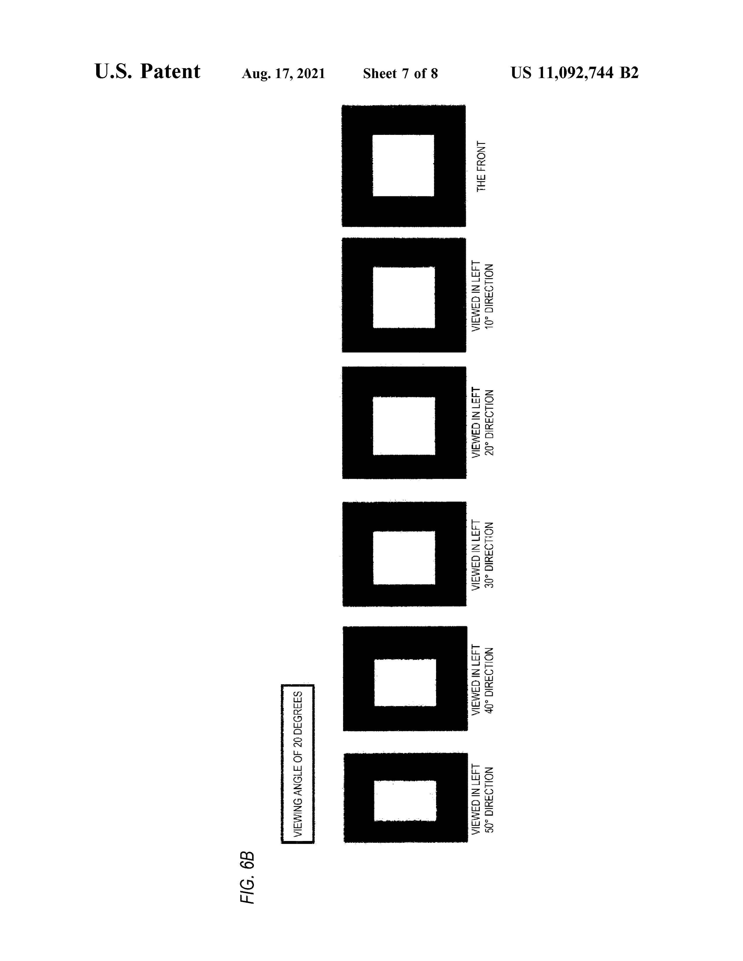
FIG . 6B is a schematic view showing a result of simu- 10 the emitting elements 11 is incident to the light inci 21. In order to make the light to be incident guide portion 20 , and shows a case of being viewed from a to the light incidence surfaces 21 from the light emitting position with the viewing angle of 20 degrees.
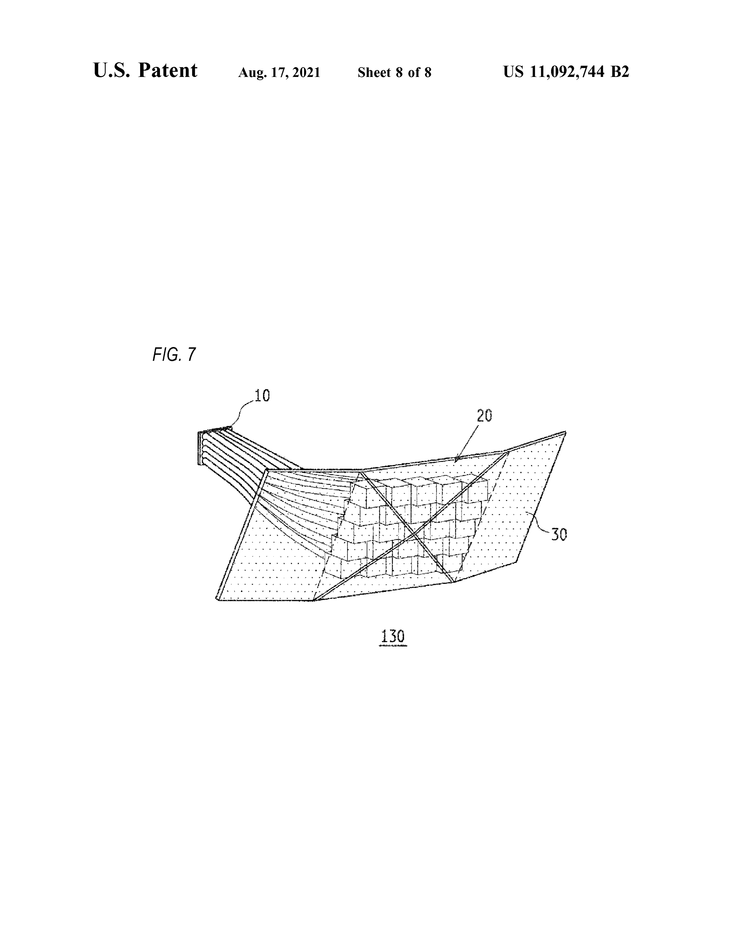
FIG . 7 is a schematic perspective view showing a three elements 11 satisfactorily, it is preferable to make a distance dimensionalsurface display device 130 according to one or 15 between each of corresponding lighttheincidence light emitting surfaceelements 21 shorter11 and and uni the more embodiments of the present invention . form . In addition , in order to improve an optical coupling DETAILED DESCRIPTION efficiency between the light emitting element 11 and the corresponding light guide portion 20, it is preferable to form
Hereinafter,embodiments of the present invention will be 20 an antireflection film or a lens shape on the light incidence described in detail with reference to the drawings. The same surface 21 .
or equivalent components, members, and processes illus- The light extraction surfaces 22 are arranged three - di trated in the drawings are denoted by the same reference mensionally adjacent to each other, and the light propagated numerals, and a repetitive description thereof will be omit- through the light guide portions 20 is extracted to the outside ted . FIGS . 1A and 1B are schematic views showing a 25 from the light extraction surfaces 22. In a side surface three - dimensional surface display device 100 according to portion of each of the light guide portions 20 , since the light the present embodiment, FIG . 1A is a schematic perspective propagating inside is substantially totally reflected due to a view , and FIG . 1B is an exploded perspective view. As difference in a refractive index, almost all of an amount of shown in FIGS . 1A and 1B , the three - dimensional surface light incident from the light incidence surfaces 21 is display device 100 includes a mounting member 10 , a 30 extracted from the light extraction surfaces 22 without plurality of light guide portions 20 , and an outer panel 30 . leakage of light from the side surface portion . In addition , a The mounting member 10 is a member on which a reflective film may be formed on a side surface of each of the plurality of light emitting elements 11 are mounted , and a light guide portions 20 so that the light propagating inside wiring pattern (not shown ) for supplying electric power to the light guide portions 20 does not leak from the side each of the light emitting elements 11 is formed . The 35 surface portion. In order to reduce a directivity of the light mounting member 10 is not limited in a material as long as extracted to the outside from the light extraction surfaces 22 it can hold the plurality of light emitting elements 11 and and improve a visibility from multiple directions , it is supplies the electric power, and a known printed wiring preferable to form a light scattering structure for scattering substrate , a ceramic substrate , a composite substrate, or the and extracting the light such as minute unevenness on like can be used . In order to satisfactorily dissipate heat 40 surfaces of the light extraction surfaces 22 . generated by light emission of the light emitting elements The plurality of adjacent light extraction surfaces 22 are 11 , the mounting member 10 is preferably made of a three -dimensionally arranged along an inner surface shape material having a good thermal conductivity. Although of the outer panel 30 , and the light from the light emitting FIGS . 1A and 1B show an example in which the light elements 11 is extracted to the outside of the three - dimen emitting elements 11 are mounted in a matrix on the sub- 45 sional surface display device 100 via the light extraction stantially rectangular flat plate - shaped mounting member surfaces 22 and the outer panel 30. Since the light incidence 10 , other polygonal shapes or circular shapes may be used , surface 21 of the light guide portion 20 faces the light or a curved surface shape or a polyhedral shape may also be emitting element 11 , each of the light extraction surfaces 22 used . functions as a pixel corresponding to the light emitting Each of the light emitting elements 11 is a member which 50 element 11. Since the light guide portions 20 are provided to is mounted on the mounting member 10 , is electrically the respective light extraction surfaces 22 arranged along the connected to the corresponding wiring pattern , and emits inner surface shape of the outer panel 30 from the respective light of a predetermined color and intensity by supplying the light incidence surfaces 21 arranged to face the correspond electric power. As the light emitting element 11 , a light ing light emitting element 11 on the mounting member 10 , emitting diode (LED ) , an organic electro luminescence 55 a length of each of the light guide portions 20 differs ( EL ) , or the like can be used . Although the light emitting according to the inner surface shape of the outer panel 30 . element 11 can use a package which emits a single color, a The outer panel 30 is a plate - shaped member made of a color image can be displayed on the three - dimensional material which transmits at least a part of light and has a surface display device 100 by using a package which can three -dimensional curved shape. In addition, the outer panel emit RGB colors . As an example, the light emitting element 60 30 is a member arranged on an exterior portion of the 11 uses a full - color LED package in which a red LED , a vehicle , and an outer surface thereof functions as a part of green LED , and a blue LED are each included in a single an exterior surface of the vehicle. As described above, the package, an electrode is provided corresponding to each plurality of light extraction surfaces 22 are three -dimension color, and light intensity of each of the RGB colors is ally arranged along the inner surface of the outer panel 30 , adjusted according to the electric power supplied to each 65 and the light extracted from the light extraction surfaces 22 electrode, so that a desired color can be emitted by mixing is transmitted through the outer panel 30 and is visible from colors . the outside of the vehicle .
Page 13
Specific examples of the material forming the outer panel In FIGS . 1A and 1B , each of the light guide portions 20 30 include glass , acrylic resin , epoxy resin , polycarbonate, is a quadrangular prism having a substantially square cross or the like . Since the outer panel 30 is a part of the exterior section , but may have another cross - sectional shape, such as surface of the vehicle, the polycarbonate is most preferable a triangular prism , a hexagonal prism , or a cylinder. When from a viewpoint of weight reduction, an impact resistance, 5 the quadrangular prism having the substantially square cross a weather resistance , a translucency, or the like . The outer section is used , since the light extraction surfaces 22 can be panel 30 may be made of a transparent material having a arranged in a matrix , it is preferable that pixels for image high translucency, and the light extraction surfaces 22 may display are easily configured. In addition , FIGS . 1A and 1B be directly visible from the outside . Besides, the light show an example in which the cross - sectional shapes in the extraction surfaces 22 may also not be directly visible from 10 plurality of light guide portions 20 and the light extraction the outside as a structure in which the light is scattered and surfaces 22 are the same , but the shape of the light extraction surfaces 22 can be set according to content displayed by the transmitted by forming the light scattering structure on the three - dimensional surface display device 100. For example , inner surface of the outer panel 30 and mixing a light the light guide portion 20 may include an icon shape light scattering member. 15 extraction surface 22 which displays specific information . A control unit (not shown ) which supplies electric power Next , another embodiment of the present invention will to the mounting member 10 is connected to the three be described with reference to FIGS . 2A and 2B . Descrip dimensional surface display device 100. The control unit is tions that are the same as those of the previous embodiment an information processing means including various comput- will be omitted . FIGS . 2A and 2B are schematic views ing devices , an internal storage device, an external storage 20 showing a three - dimensional surface display device 110 device, an information communication means , and various according to the present embodiment, FIG . 2A is a sche sensors . The control unit may be a part of the information matic perspective view , and FIG . 2B is an exploded per processing means of an automatic driving technique of the spective view. Also in the present embodiment, the three vehicle, or may be configured by an information processing dimensional surface display device 110 includes the means different from the automatic driving technique. The 25 mounting member 10 , the light guide portions 20 , and the control unit generates information such as a driving situation outer panel 30. The present embodiment is different from the and a traveling state to be presented to the outside of the previous embodiment in that each of the light guide portions vehicle as image information , determines a light emission 20 includes an optical fiber 23 and a columnar member 24 . color and a light emission intensity of each light emitting In FIG . 2B , one optical fiber 23 and one columnar member element 11 in correspondence with a pixel of the image 30 24 are described for simplification , but the three -dimen information, and supplies appropriate electric power to each sional surface display device 110 includes the same number light emitting element 11 . of optical fibers 23 and columnar members 24 as the light The plurality of light emitting elements 11 arranged in a emitting elements 11 as shown in FIG . 2A . matrix on the mounting member 10 emit light with the light The optical fiber 23 is a substantially linear flexible emission color and emission intensity of each pixel accord- 35 member made of a translucent material. One end surface of ing to the image information , and the light is incident on the the optical fiber 23 is the light incidence surface 21 and is facing light incidence surfaces 21. As described above , the arranged to face the corresponding light emitting element light incident on the light incidence surfaces 21 propagates 11 , and the other end surface of the optical fiber 23 is a light inside the light guide portions 20 , and is extracted from the emitting surface and is optically coupled to the correspond light extraction surfaces 22 to the outside of the three- 40 ing columnar member 24. In order to improve the optical dimensional surface display device 100 via the outer panel coupling efficiency between the light emitting element 11 30 . and the corresponding optical fiber 23 , it is preferable to Since each of the light extraction surfaces 22 forms a pixel form an antireflection film or a lens shape on the light corresponding to the light emitting element 11 , it is possible incidence surface 21 .
to display an image of a three - dimensional surface according 45 The columnar member 24 is a substantially columnar to the curved surface shape of the outer panel 30 in the member made of a material which transmits light from the three - dimensional surface display device 100 . light emitting element 11 , and one end surface thereof is In the three - dimensional surface display device 100 optically coupled to the optical fiber 23 , and the other end according to the present embodiment, the light extraction surface thereof is the light extraction surface 22. The light surfaces 22 can be three -dimensionally arranged adjacent to 50 extraction surfaces 22 are arranged three -dimensionally each other along the inner surface of the outer panel 30 by adjacent to each other, and the light propagated through the only adjusting the lengths of the light guide portions 20 light guide portions 20 is extracted to the outside from the according to the shape of the outer panel 30 , and it is light extraction surfaces 22. The plurality of columnar possible to display a three - dimensional image with a simple members 24 may have different lengths, but when the structure. In addition, since the light emitted from the light 55 lengths of all the columnar members 24 are made uniform as emitting elements 11 is extracted from the light extraction shown in FIG . 2A , the parts can be shared and the number surfaces 22 , a light emitting area can be secured as compared of parts can be reduced .
with a case where the light emitting elements 11 are arranged In side surface portions of the optical fibers 23 and the close to the outer panel 30 to emit light in a dot shape . columnar members 24 , since the light propagating inside is Therefore, even when a picture, a character, or the like is 60 substantially totally reflected due to the difference in the displayed, it is possible to improve an identification of a refractive index, almost all of the amount of the light contour of the image and to facilitate information transmis- incident from the light incidence surfaces 21 is extracted sion . Further, the outer panel 30 is a part of the exterior of from the light extraction surfaces 22 without the leakage of the vehicle , so that a visibility from the outside of the vehicle the light from the side surface portions. In order to reduce can be improved , and a novel appearance can be realized , 65 the directivity of the light extracted to the outside from the thereby enhancing a sense of unity with the vehicle and a light extraction surfaces 22 and improve the visibility from design . the multiple directions , it is preferable to form the light
Page 14
scattering structure for scattering and extracting the light center of the insertion hole 41 is a position corresponding to such as minute unevenness on the surfaces of the light a light emission center of the corresponding light emitting extraction surfaces 22. The lengths of the plurality of optical element 11 on the mounting member 10. The fiber holding fibers 23 from the respective light incidence surfaces 21 to member 40 is arranged to face the mounting member 10 in the respective light emitting surfaces are different, and the 5 a state in which the optical fibers 23 are inserted and held in length of the columnar member 24 to the light extraction respective insertion holes 41 , and the light incidence sur surface 22 is adjusted by adjusting the length of the optical faces 21 of the optical fibers 23 are held so as to face the fiber 23 . light emitting elements 11 .
The plurality of adjacent light extraction surfaces 22 are In the three - dimensional surface display device 120 three -dimensionally arranged along the inner surface shape 10 according to the present embodiment, since the plurality of of the outer panel 30 , and the light from the light emitting optical fibers 23 are held by using the fiber holding member elements 11 is extracted to the outside of the three - dimen- 40 to face the respective light emitting element 11 , optical sional surface display device 110 via the light extraction axes of each optical fiber 23 and the corresponding light surfaces 22 and the outer panel 30 . emitting element 11 are easily aligned . In addition , since the The light incident on the light incidence surfaces 21 15 plurality of optical fibers 23 are collectively held by the fiber propagates inside the respective optical fibers 23 and the holding member 40 , the optical fibers 23 having a flexibility respective columnar members 24 , and is extracted from the can be easily handled even when the three - dimensional respective light extraction surfaces 22 to the outside of the surface display device 120 is assembled . three - dimensional surface display device 110 via the outer FIG . 3 shows an example in which one fiber holding panel 30. Since each of the light extraction surfaces 22 forms 20 member 40 is provided , but a plurality of fiber holding a pixel corresponding to the light emitting element 11 , it is members 40 may be provided to hold intermediate positions possible to display an image of a three - dimensional surface of the optical fibers 23. In this case , in the fiber holding according to the curved surface shape of the outer panel 30 member 40 holding the vicinity of the light incidence in the three - dimensional surface display device 110 . surfaces 21 , the insertion holes 41 are formed at positions In the three - dimensional surface display device 110 25 corresponding to the light emitting elements 11 , but a size of according to the present embodiment, since the light guide the fiber holding member 40 holding the intermediate posi portion 20 includes the optical fiber 23 and the columnar tions of the optical fibers 23 is not limited , and an interval member 24 , the length of the columnar member 24 having between the insertion holes 41 may be narrowed to bundle a larger cross - sectional area than that of the optical fiber 23 the optical fibers 23 .
can be shortened , so that the entire light guide portion 20 can 30 Next , another embodiment of the present invention will be reduced in weight. In addition , since the lengths of the be described with reference to FIG . 4. FIG . 4 is a schematic entire light guide portions 20 can be adjusted by adjusting perspective view showing the light guide portion 20 in the the lengths of the respective optical fibers 23 , the number of present embodiment. In the present embo ent, a configu parts can be reduced by making the columnar members 24 ration of the light guide portion 20 is different from that of all the same length and sharing parts. Further, since the 35 the previous embodiment, and the other configurations are optical fiber 23 is a flexible linear member, a distance same as those of the previous embodiment, and therefore the between the mounting member 10 and the outer panel 30 can same description will be omitted .
be increased , and a degree of freedom in layout can be As shown in FIG . 4 , in the present embodiment, the light improved . guide portion 20 includes the optical fiber 23 and the Next, another embodiment of the present invention will 40 columnar member 24 , and a light expanding portion 25 be described with reference to FIG . 3. Descriptions that are having a diameter reduced toward the optical fiber 23 is the same as those of the previous embodiment will be provided on a side of the columnar member 24 to which the omitted . FIG . 3 is an exploded perspective view showing a optical fiber 23 is connected . In addition, a fiber insertion three - dimensional surface display device 120 according to portion 26 for inserting and fixing a light emitting side end the present embodiment. The three -dimensional surface dis- 45 surface of the optical fiber 23 is formed at a tip end of the play device 120 of the present embodiment includes the light expanding portion 25 .
mounting member 10 , the light guide portions 20 , the outer In the light expanding portion 25 , one side has a circular panel 30 , and a fiber holding member 40. The present cross section approximate to an outer diameter of the optical embodiment is different from the previous embodiment in fiber 23 , and the other side has the same cross - sectional that the plurality of optical fibers 23 are held by the fiber 50 shape as the light extraction surface 22 , and the light holding member 40 . expanding portion 25 has a shape whose a diameter The fiber holding member 40 is a member having a increases from the optical fiber 23 side toward the light substantially flat plate shape in which a plurality of insertion extraction surface 22 direction . In other words , the light holes 41 are formed , and is a member for inserting and expanding portion 25 has a shape in which a part of the holding the optical fibers 23 in respective insertion holes 41. 55 columnar member 24 is cut out at a conical side surface . The fiber holding member 40 has substantially the same The fiber insertion portion 26 is a substantially cylindrical shape as the mounting member 10 , and is formed with the concave portion provided on one end side of the light insertion holes 41 at positions corresponding to the light expanding portion 25 , and an inner diameter thereof is emitting elements 11. In FIG . 3 , one optical fiber 23 and one substantially the same as the outer diameter of the light columnar member 24 are described for simplification , but 60 emitting end surface of the optical fiber 23. A depth of the the three - dimensional surface display device 120 includes concave portion of the fiber insertion portion 26 is prefer the same number of optical fibers 23 and columnar members ably about several mm in order to insert and fix a light 24 as the light emitting elements 11 . emitting end side of the optical fiber 23. In a state in which The insertion hole 41 is a hole provided so as to penetrate the light emitting end side of the optical fiber 23 is inserted from one surface to a back surface of the fiber holding 65 into the fiber insertion portion 26 , the optical fiber 23 and the member 40 , and a diameter thereof is substantially the same fiber insertion portion 26 are fixed by applying an adhesive as an outer diameter of the optical fiber 23. In addition, a or the like around a connection portion .
Page 15
A concave portion having a conical shape or the like is By inserting and fixing the light emitting end side of the formed on the light extraction surface 22 side of the fiber optical fiber 23 into the fiber insertion portion 26 , the optical insertion portion 26 , and a gap is formed between a material fiber 23 and the light expanding portion 25 can be satisfac forming the light expanding portion 25 and the light emitting torily fixed , and optical coupling therebetween can be main end surface of the optical fiber 23. The light expanding 5 tained. In addition, by appropriately designing a shape of the gap provided at the tip end of the fiber insertion portion 26 , portion 25 has a function of increasing a light diameter in the the same manner as a concave lens due to a difference in a light diameter expansion at the light expanding portion refractive index of the gap between the material forming the 25 and the columnar member 24 can be set. light expanding portion 25 and the concave portion. There Next , another embodiment of the present invention will fore, thelight incident to the light expanding portion 25 from 10 bethedescribed with reference to FIG. 7. Descriptions that are same as those of the previous embodiment will be the light emitting end surface of the optical fiber 23 propa omitted . FIG . 7 is a schematic perspective view showing a gates inside the light expanding portion 25 while the light three - dimensional surface display device 130 according to diameter being expanded to substantially the entire area of the present embodiment. Also in the present embodiment, the light extraction surface, and is extracted from the extraction surface 22 of the columnar member 24 to the light 15 the three -dimensional surface display device 130 includes outside .
the mounting member 10 , the light guide portions 20 , and the outer panel 30 , and each of the light guide portions 20
In side surface portions of the columnar member 24 and includes the optical fiber 23 and the columnar member 24 . the light expanding portion 25 , since the light propagating In the present embodiment, as shown in FIG . 7 , a size of inside is substantially totally reflected due to the difference 20 the mounting member 10 is smaller than the total area of the in the refractive index, there is no leakage of light from the light extraction surface 22 , and the light incidence surface 21 side surface portions. In addition , a reflective film may be side of the optical fibers 23 is bundled and faces the light formed on a side surface, so that the light propagating inside emitting elements 11 of the mounting member 10 . the columnar member 24 and the light expanding portion 25 Since the diameter of the optical fiber 23 is as small as does not leak from the side surface portions. In order to 25 several tens of um to several mm , even if the size of the reduce the directivity of the light extracted to the outside mounting member 10 is reduced and the interval between from the light extraction surfaces 22 and improve the the light emitting elements 11 is narrowed , the light inci visibility from the multiple directions , it is preferable to dence surfaces 21 can be made to face the light emitting form the light scattering structure for scattering and extract- elements 11 , respectively. In addition , since the optical fiber ing the light such as minute unevenness on the surfaces of 30 23 has the flexibility, the light emitting end surface side can the light extraction surfaces 22. In addition , FIG . 4 shows an be connected to a center position of the columnar member 24 example in which the light expanding portion 25 is inte- with the mutual interval therebetween increased . Accord grally configured as a part of the columnar member 24 , but ingly, it is possible to realize a large - screen three -dimen the columnar member 24 and the light expanding portion 25 sional surface display by increasing the total area of the light may be configured separately . 35 extraction surfaces 22 while reducing the size of the mount FIG . 5A is a schematic sectional view showing shapes of ing member 10 to realize space saving and weight reduction. the optical fiber 23 , the light expanding portion 25 , and the The present invention is not limited to the embodiments fiber insertion portion 26 , and FIG . 5B is a schematic view described above , and various modifications can be made showing a simulation result of light expansion. In I to IV of within the scope of the claims , and embodiments obtained FIGS . 5A and 5B , the optical fibers 23 and the light 40 by appropriately combining technical means disclosed in the expanding portions 25 have the same shape , and a height of different embodiments are also included in the technical the conical shape of a gap portion formed at the tip end of scope of the present invention.
the fiber insertion portion 26 is changed . From results of The present application incorporates contents disclosed in simulating a light ray trajectory shown in FIG . 5B , it can be Japanese Patent Application ( Japanese Patent Application seen that expansion of the light diameter and a light distri- 45 No. 2017-075753 ) filed on Apr. 6 , 2017 . bution can be controlled by the conical shape of the gap The invention claimed is :
portion formed at the tip end of the fiber insertion portion 26 . 1. A three - dimensional surface display device comprising: FIGS . 6A and 6B are schematic views showing results of a plurality of light emitting elements which are mounted simulating a visibility on the light extraction surface of the on a mounting member; and light guide portion 20 , and FIG . 6A shows a case of being 50 a plurality of light guide portions, each of which includes viewed from a position within a viewing angle of 10 a light incidence surface on one end side and a light degrees , and FIG . 6B shows a case of being viewed from a extraction surface on the other end side, and is arranged position within the viewing angle of 20 degrees. FIGS . 6A to face the corresponding light emitting element, and 6B show the visibility from the front position of the light wherein the plurality of light guide portions have different extraction surface 22 and the visibility from a direction 55 lengths, inclined by 10 to 50 degrees from the front position to the wherein the light extraction surfaces are arranged three left. It can be seen from FIGS . 6A and 6B that the satisfac dimensionally adjacent to each other, tory light emission from substantially the entire area of the wherein each of the plurality of light guide portions light extraction surface 22 can be satisfactorily visually comprises a translucent columnar member, and one end recognized regardless of the viewing angle and a visual 60 surface of the columnar member is the light extraction direction . surface ,
In the present embodiment, since the light expanding wherein each of the plurality of light guide portions portion 25 is provided between the optical fiber 23 and the comprises an optical fiber, and columnar member 24 , the light diameter can be expanded wherein the length of each of the plurality of light guide from the optical fiber 23 to substantially the entire area of the 65 portions is adjustable.
light extraction surface 22 , and the visibility of the light 2. The three - dimensional surface display device accord extraction surface 22 can be improved. ing to claim 1 , further comprising :
Page 16
a light expanding portion configured to expand a diameter of light emitted from a light emitting end surface of the optical fiber to substantially the entire area of the light extraction surface .
3. The three - dimensional surface display device accord- 5 ing to claim 1 , wherein the light extraction surface is formed with a light scattering structure for scattering and extracting light. 4. The three - dimensional surface display device accord ing to claim 1 , further comprising: 10 a three - dimensional shaped outer panel formed of a translucent material, wherein the light extraction surfaces are arranged along an inner surface of the outer panel .
5. A vehicle display device including the three - dimen- 15 sional surface display device according to claim 4 , wherein the outer panel is arranged on an exterior portion of a vehicle .
Provenance
- Collection
- Patents citing this work
- Original assignee
- Koito Manufacturing Co Ltd
- Pages
- 16
- Method
- pdftotext (the PDF's own text layer) + pdftoppm 300dpi page scans
- Patent office record
- patents.google.com →
- Source
- Google Patents citing-documents table
- Inventors
- Ryuho Sato; Akinori Matsumoto; Haruhiko Iyoda; Hiroya Koizumi; Koito Manufacturing Co Ltd
- Published
- 2021-08-17
- Transcribed from
- patentimages.storage.googleapis.com →