patent · US4311999
Vibratory scan optical display
19 January 1982
Page 1 — bibliographic record
United States
Upton et al.
Patent (19. 45 Jan. 19, 1982 3,609,235 9/1971 Sawyer ................................ 239/327 54) WBRATORY SCAN OPTICAL DISPLAY 3,803,597 4/1974 Kirner ...... ... 340/380 (75) Inventors: Hubert W. Upton, Arlington; James 3,958,235 5/1976 Duffy .................................. 340/755 R. Goodman, Euless, both of Tex. Primary Examiner-Marshall M. Curtis 73 Assignee: Textron, Inc., Providence, R.I. Attorney, Agent, or Firm-Richards, Harris & Medlock (21) Appl. No.: 119,469 57 ABSTRACT (22) Filed: Feb. 7, 1980 A raster-type personal display is provided by vibrating 51 Int. Cl'................................................ G06F 3/14 an array of fiber optic filaments (32) between display (52) U.S. C. .................................... 340/755; 340/380; limit (52, 54) by means of an electromechanical exciter 340/706; 340/.407 (36). One end of the fiber optic filaments (32) is cantile (58) Field of Search ............... 340/705, 755, 380, 706, ver mounted to an array of light emitting diodes (34), 340/.407 with the second end of the filaments free to be vibrated
References Cited by the exciter (36). Drive signals for energizing the light 56 emitting diodes (34) are generated by a symbol genera
2,137,888 1/1938 Fuller .................................. 179/ R. position detector consisting of a light source (58), a 2,176, 167 10/1939 Comstock ............. 35/50 shutter (56) and a light responsive pickup (60). 2,595,701 5/1952 Rotter .............. ... 17.9/100.3 B 3,436,885 4/1969 Conrose, Sr. ......................... 52/207 17 Claims, 7 Drawing Figures 3,463,885 8/1969 Upton ................................. iT9/ R.
MCROPROCESSOR auFFER CONTROL --
UFFer
AMPuTube
COL-NTR Driver s O
i. NTERFACE
NPUT s 79
AMP
CONTROL OSC
Page 2
Drawing sheet — no readable text.
Page 3
e - - - - - - - - - - - - - - - - - - - - a- - - - - - -- -- - us -- 99
one s - . -. - . us. -. -. me. -. -. -. -. -. -. - . - .- .- - -
a cood
Page 4
Drawing sheet — no readable text.
Page 5
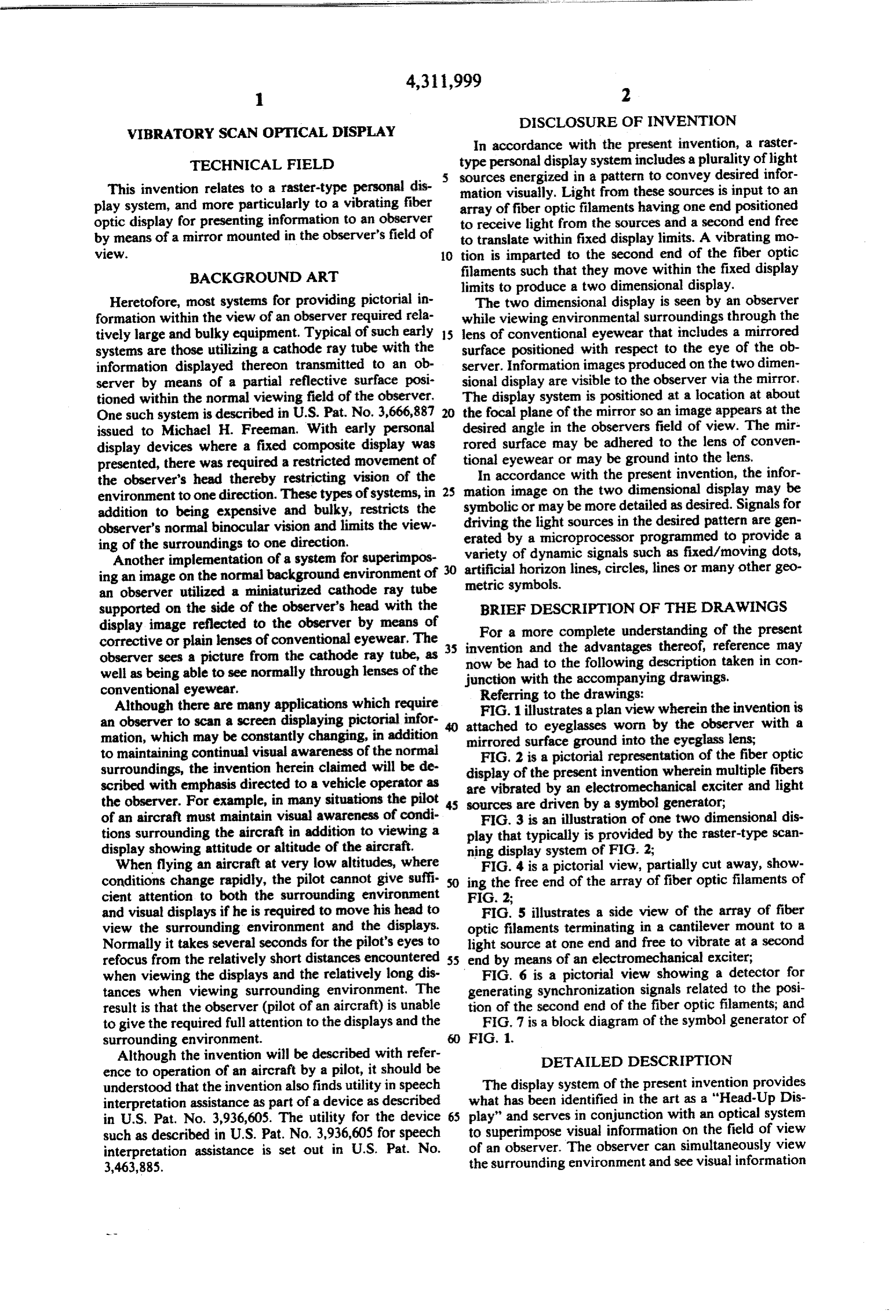
DISCLOSURE OF INVENTION
VIBRATORY SCAN OPTICAL DISPLAY
In accordance with the present invention, a raster
TECHNICAL FIELD type personal display system includes a plurality of light 5 sources energized in a pattern to convey desired infor
This invention relates to a raster-type personal dis mation visually. Light from these sources is input to an play system, and more particularly to a vibrating fiber array of fiber optic filaments having one end positioned optic display for presenting information to an observer to receive light from the sources and a second end free by means of a mirror mounted in the observer's field of to translate within fixed display limits. A vibrating mo WeW. O tion is imparted to the second end of the fiber optic BACKGROUND ART filaments such that they move within the fixed display limits to produce a two dimensional display.
Heretofore, most systems for providing pictorial in The two dimensional display is seen by an observer formation within the view of an observer required rela while viewing environmental surroundings through the tively large and bulky equipment. Typical of such early 15 lens of conventional eyewear that includes a mirrored systems are those utilizing a cathode ray tube with the surface positioned with respect to the eye of the ob information displayed thereon transmitted to an ob server. Information images produced on the two dimen server by means of a partial reflective surface posi sional display are visible to the observer via the mirror. tioned within the normal viewing field of the observer. The display system is positioned at a location at about One such system is described in U.S. Pat. No. 3,666,887 20 the focal plane of the mirror so an image appears at the issued to Michael H. Freeman. With early personal desired angle in the observers field of view. The mir display devices where a fixed composite display was rored surface may be adhered to the lens of conven presented, there was required a restricted movement of tional eyewear or may be ground into the lens. the observer's head thereby restricting vision of the In accordance with the present invention, the infor environment to one direction. These types of systems, in 25 mation image on the two dimensional display may be addition to being expensive and bulky, restricts the symbolic or may be more detailed as desired. Signals for driving the light sources in the desired pattern are gen observer's normal binocular vision and limits the view ing of the surroundings to one direction. erated by a microprocessor programmed to provide a Another implementation of a system for superimpos 30 variety artificial of dynamic signals such as fixed/moving dots, horizon lines, circles, lines or many other geo ing an image on the normal background environment of metric symbols.
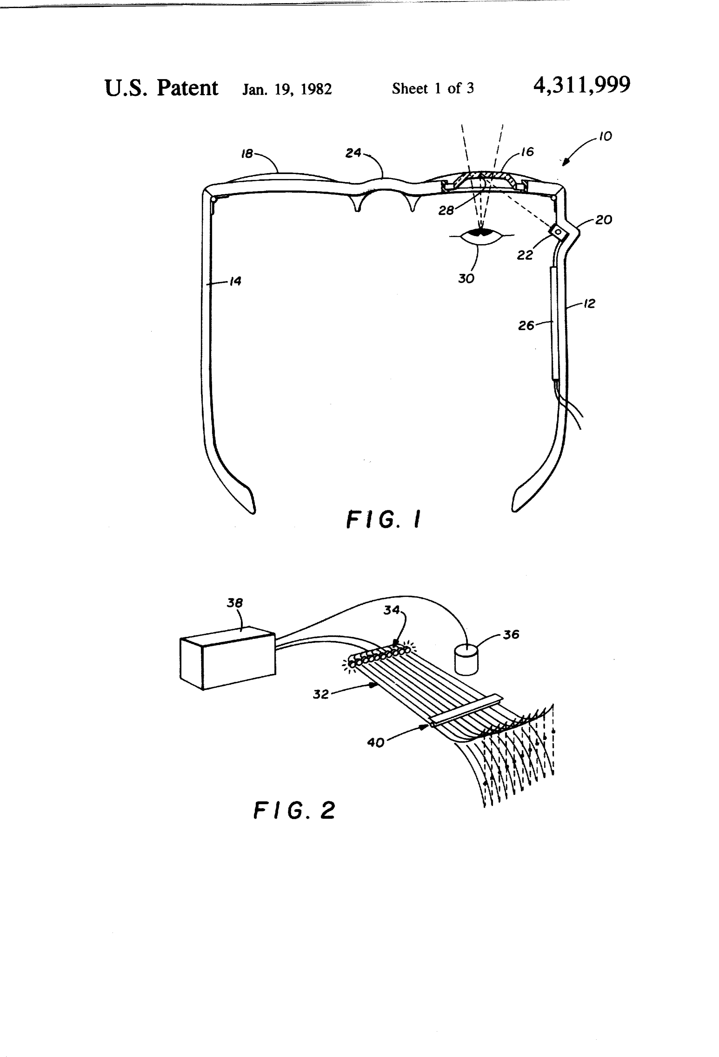
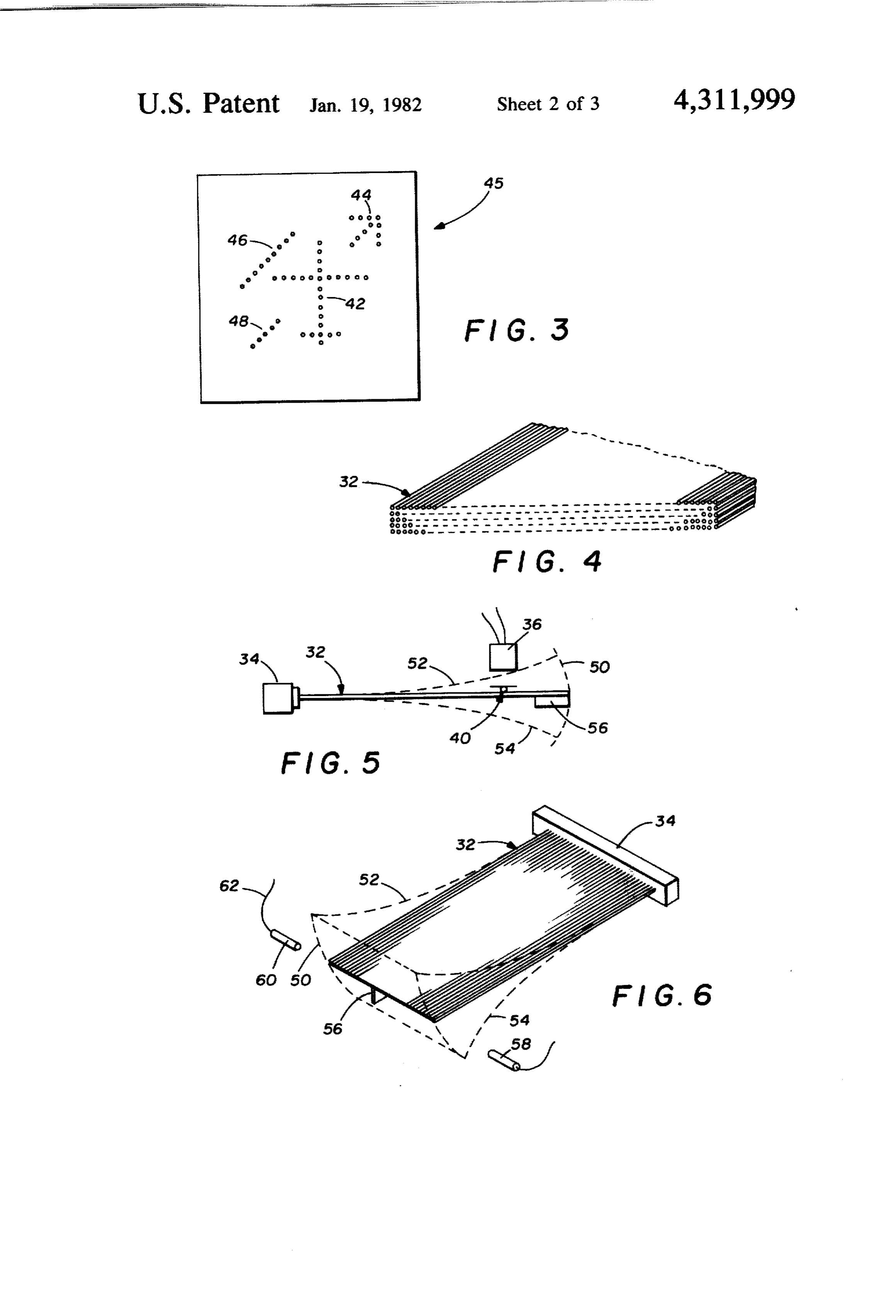
an observer utilized a miniaturized cathode ray tube supported on the side of the observer's head with the BRIEF DESCRIPTION OF THE DRAWINGS display image reflected to the observer by means of For a more complete understanding of the present corrective or plain lenses of conventional eyewear. The 35 invention observer sees a picture from the cathode ray tube, as now be hadandto the the advantages thereof, reference may following description taken in con well as being able to see normally through lenses of the junction with the accompanying drawings. conventional eyewear. Referring to the drawings: Although there are many applications which require FIG. 1 illustrates a plan view wherein the invention is an observer to scan a screen displaying pictorial infor O attached to eyeglasses worn by the observer with a mation, which may be constantly changing, in addition mirrored surface ground into the eyeglass lens; to maintaining continual visual awareness of the normal FIG. 2 is a pictorial representation of the fiber optic surroundings, the invention herein claimed will be de display of the present invention wherein multiple fibers scribed with emphasis directed to a vehicle operator as are vibrated by an electromechanical exciter and light the observer. For example, in many situations the pilot sources are driven by a symbol generator; of an aircraft must maintain visual awareness of condi FIG. 3 is an illustration of one two dimensional dis tions surrounding the aircraft in addition to viewing a play that typically is provided by the raster-type scan display showing attitude or altitude of the aircraft. ning display system of FIG. 2; When flying an aircraft at very low altitudes, where FIG. 4 is a pictorial view, partially cut away, show conditions change rapidly, the pilot cannot give suffi ing the free end of the array of fiber optic filaments of cient attention to both the surrounding environment FIG. 2;
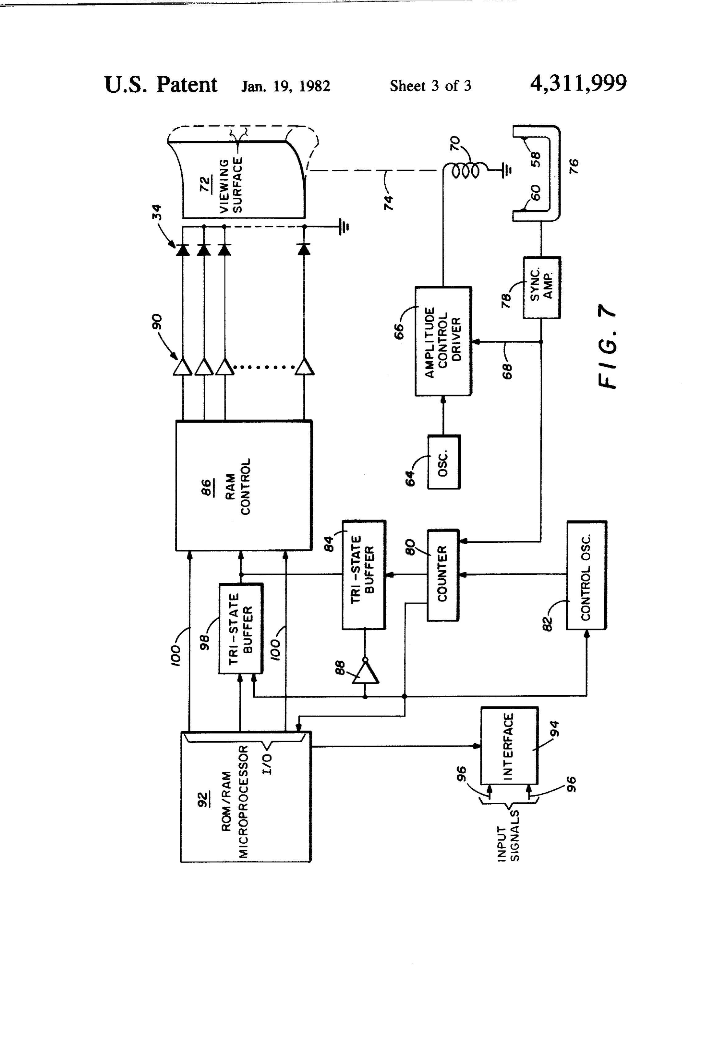
and visual displays if he is required to move his head to FIG. 5 illustrates a side view of the array of fiber view the surrounding environment and the displays. optic filaments terminating in a cantilever mount to a Normally it takes several seconds for the pilot's eyes to light source at one end and free to vibrate at a second refocus from the relatively short distances encountered 55 end by means of an electromechanical exciter; when viewing the displays and the relatively long dis FIG. 6 is a pictorial view showing a detector for tances when viewing surrounding environment. The generating synchronization signals related to the posi result is that the observer (pilot of an aircraft) is unable tion of the second end of the fiber optic filaments; and to give the required full attention to the displays and the FIG. 7 is a block diagram of the symbol generator of surrounding environment. F.G. 1.
Although the invention will be described with refer DETAILED DESCRIPTION ence to operation of an aircraft by a pilot, it should be understood that the invention also finds utility in speech The display system of the present invention provides interpretation assistance as part of a device as described what has been identified in the art as a "Head-Up Dis in U.S. Pat. No. 3,936,605. The utility for the device 65 play" and serves in conjunction with an optical system such as described in U.S. Pat. No. 3,936,605 for speech to superimpose visual information on the field of view interpretation assistance is set out in U.S. Pat. No. of an observer. The observer can simultaneously view 3,463,885. the surrounding environment and see visual information
Page 6
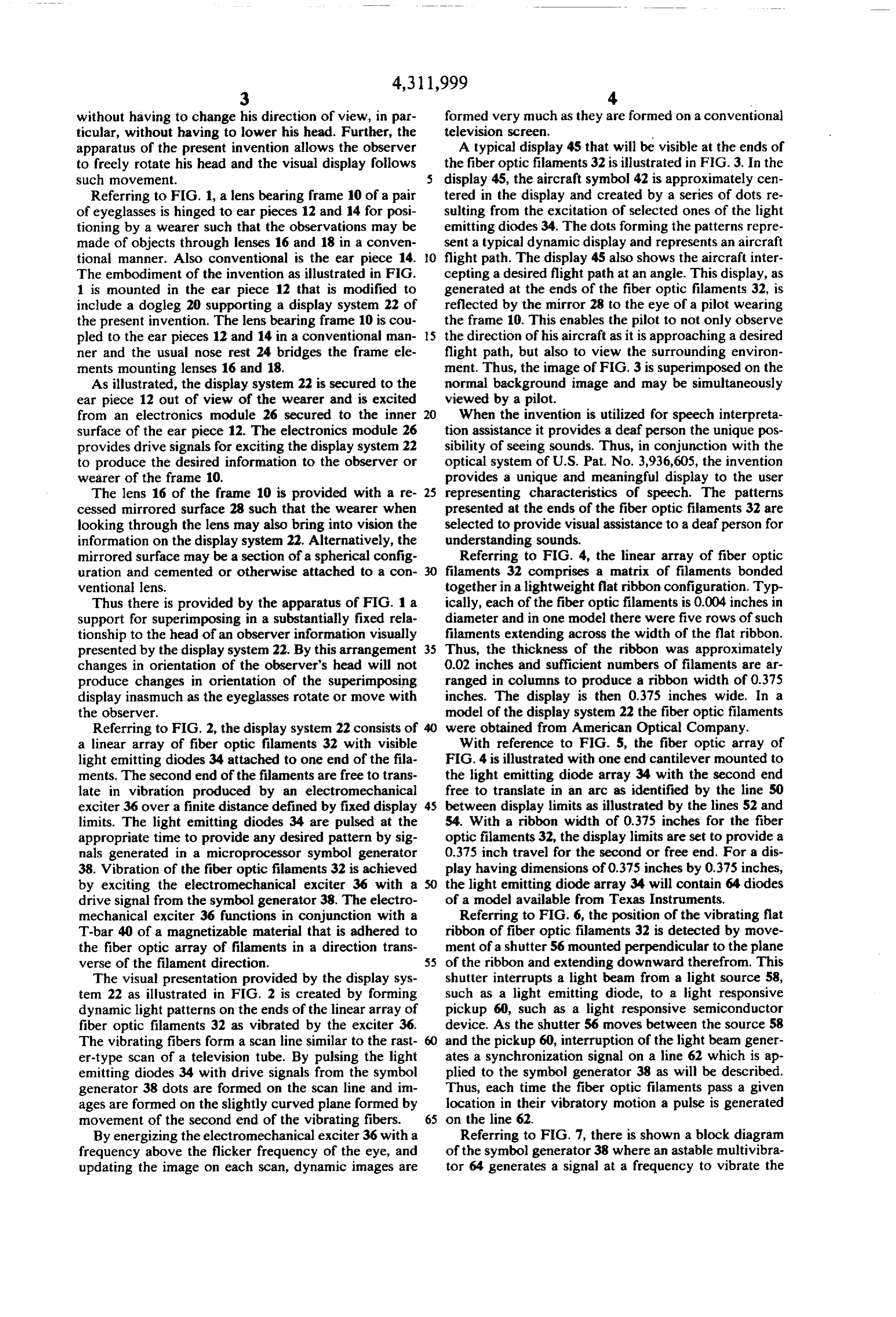
without having to change his direction of view, in par formed very much as they are formed on a conventional ticular, without having to lower his head. Further, the television screen.
apparatus of the present invention allows the observer A typical display 45 that will be visible at the ends of to freely rotate his head and the visual display follows the fiber optic filaments 32 is illustrated in FIG. 3. In the such movement. 5 display 45, the aircraft symbol 42 is approximately cen Referring to FIG. 1, a lens bearing frame 10 of a pair tered in the display and created by a series of dots re of eyeglasses is hinged to ear pieces 12 and 14 for posi sulting from the excitation of selected ones of the light tioning by a wearer such that the observations may be emitting diodes 34. The dots forming the patterns repre made of objects through lenses 16 and 18 in a conven sent a typical dynamic display and represents an aircraft tional manner. Also conventional is the ear piece 14. 10 flight path. The display 45 also shows the aircraft inter The embodiment of the invention as illustrated in FIG. cepting a desired flight path at an angle. This display, as 1 is mounted in the ear piece 12 that is modified to generated at the ends of the fiber optic filaments 32, is include a dogleg 20 supporting a display system 22 of reflected by the mirror 28 to the eye of a pilot wearing the present invention. The lens bearing frame 10 is cou the frame 10. This enables the pilot to not only observe pled to the ear pieces 12 and 14 in a conventional man- 15 the direction of his aircraft as it is approaching a desired ner and the usual nose rest 24 bridges the frame ele flight path, but also to view the surrounding environ ments mounting lenses 16 and 18. ment. Thus, the image of FIG. 3 is superimposed on the As illustrated, the display system 22 is secured to the normal background image and may be simultaneously ear piece 12 out of view of the wearer and is excited viewed by a pilot.
from an electronics module 26 secured to the inner 20 When the invention is utilized for speech interpreta surface of the ear piece 12. The electronics module 26 tion assistance it provides a deaf person the unique pos provides drive signals for exciting the display system 22 sibility of seeing sounds. Thus, in conjunction with the to produce the desired information to the observer or optical system of U.S. Pat. No. 3,936,605, the invention wearer of the frame 10. provides a unique and meaningful display to the user The lens 16 of the frame 10 is provided with a re- 25 representing characteristics of speech. The patterns cessed mirrored surface 28 such that the wearer when presented at the ends of the fiber optic filaments 32 are looking through the lens may also bring into vision the selected to provide visual assistance to a deaf person for information on the display system 22. Alternatively, the understanding sounds.
mirrored surface may be a section of a spherical config Referring to FIG. 4, the linear array of fiber optic uration and cemented or otherwise attached to a con- 30 filaments 32 comprises a matrix of filaments bonded ventional lens. together in a lightweight flat ribbon configuration. Typ Thus there is provided by the apparatus of FIG. 1 a ically, each of the fiber optic filaments is 0.004 inches in support for superimposing in a substantially fixed rela diameter and in one model there were five rows of such tionship to the head of an observer information visually filaments extending across the width of the flat ribbon. presented by the display system 22. By this arrangement 35 Thus, the thickness of the ribbon was approximately changes in orientation of the observer's head will not 0.02 inches and sufficient numbers of filaments are ar produce changes in orientation of the superimposing ranged in columns to produce a ribbon width of 0.375 display inasmuch as the eyeglasses rotate or move with inches. The display is then 0.375 inches wide. In a the observer. model of the display system 22 the fiber optic filaments Referring to FIG. 2, the display system 22 consists of 40 were obtained from American Optical Company. a linear array of fiber optic filaments 32 with visible With reference to FIG. 5, the fiber optic array of light emitting diodes 34 attached to one end of the fila FIG. 4 is illustrated with one end cantilever mounted to ments. The second end of the filaments are free to trans the light emitting diode array 34 with the second end late in vibration produced by an electromechanical free to translate in an arc as identified by the line 50 exciter 36 over a finite distance defined by fixed display 45 between display limits as illustrated by the lines 52 and limits. The light emitting diodes 34 are pulsed at the 54. With a ribbon width of 0.375 inches for the fiber appropriate time to provide any desired pattern by sig optic filaments 32, the display limits are set to provide a nals generated in a microprocessor symbol generator 0.375 inch travel for the second or free end. For a dis 38. Vibration of the fiber optic filaments 32 is achieved play having dimensions of 0.375 inches by 0.375 inches, by exciting the electromechanical exciter 36 with a 50 the light emitting diode array 34 will contain 64 diodes drive signal from the symbol generator 38. The electro of a model available from Texas Instruments. mechanical exciter 36 functions in conjunction with a Referring to FIG. 6, the position of the vibrating flat T-bar 40 of a magnetizable material that is adhered to ribbon of fiber optic filaments 32 is detected by move the fiber optic array of filaments in a direction trans ment of a shutter 56 mounted perpendicular to the plane verse of the filament direction. 55 of the ribbon and extending downward therefrom. This The visual presentation provided by the display sys shutter interrupts a light beam from a light source 58, tem 22 as illustrated in FIG. 2 is created by forming such as a light emitting diode, to a light responsive dynamic light patterns on the ends of the linear array of pickup 60, such as a light responsive semiconductor fiber optic filaments 32 as vibrated by the exciter 36. device. As the shutter 56 moves between the source 58 The vibrating fibers form a scan line similar to the rast- 60 and the pickup 60, interruption of the light beam gener er-type scan of a television tube. By pulsing the light ates a synchronization signal on a line 62 which is ap emitting diodes 34 with drive signals from the symbol plied to the symbol generator 38 as will be described. generator 38 dots are formed on the scan line and im Thus, each time the fiber optic filaments pass a given ages are formed on the slightly curved plane formed by location in their vibratory motion a pulse is generated movement of the second end of the vibrating fibers. 65 on the line 62.
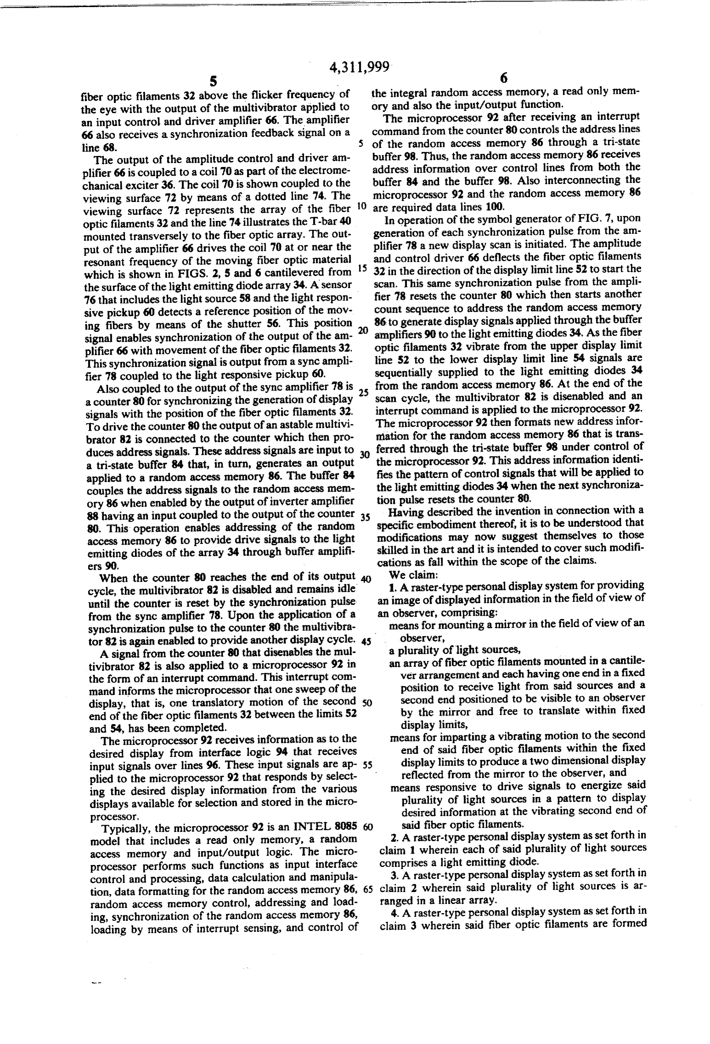
By energizing the electromechanical exciter 36 with a Referring to FIG. 7, there is shown a block diagram frequency above the flicker frequency of the eye, and of the symbol generator 38 where an astable multivibra updating the image on each scan, dynamic images are tor 64 generates a signal at a frequency to vibrate the
Page 7
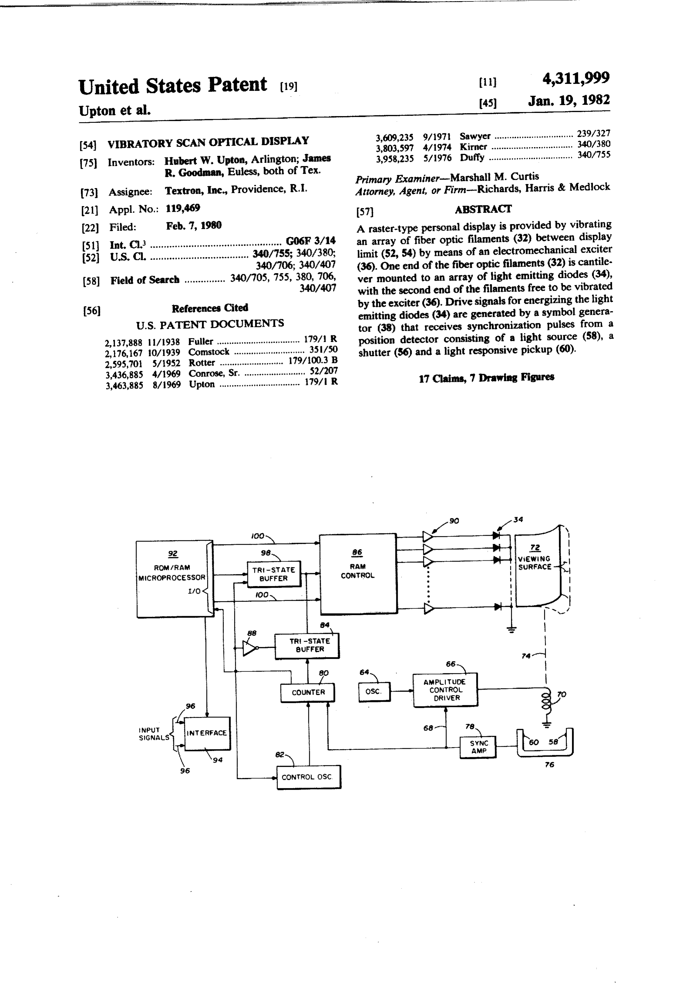
fiber optic filaments 32 above the flicker frequency of the integral random access memory, a read only mem the eye with the output of the multivibrator applied to ory and also the input/output function. an input control and driver amplifier 66. The amplifier The microprocessor 92 after receiving an interrupt 66 also receives a synchronization feedback signal on a command from the counter 80 controls the address lines line 68. of the random access memory 86 through a tri-state The output of the amplitude control and driver am buffer 98. Thus, the random access memory 86 receives plifier 66 is coupled to a coil 70 as part of the electrome address information over control lines from both the chanical exciter 36. The coil 70 is shown coupled to the buffer 84 and the buffer 98. Also interconnecting the viewing surface 72 by means of a dotted line 74. The O microprocessor 92 and the random access memory 86 viewing surface 72 represents the array of the fiber areInrequired data lines 100.
operation of the symbol generator of FIG, 7, upon optic filaments 32 and the line 74 illustrates the T-bar 40 generation of each synchronization pulse from the am nounted transversely to the fiber optic array. The out put of the amplifier 66 drives the coil 70 at or near the plifier 78 a new display scan is initiated. The amplitude resonant frequency of the moving fiber optic material and control driver 66 deflects the fiber optic filaments which is shown in FIGS. 2, 5 and 6 cantilevered from 15 32 in the direction of the display limit line 52 to start the the surface of the light emitting diode array34. A sensor scan. This same synchronization pulse from the ampli fier 78 resets the counter 80 which then starts another 76 that includes the light source 58 and the light respon sive pickup 60 detects a reference position of the mov count sequence to address the random access memory ing fibers by means of the shutter 56. This position 20 86 to generate display signals applied through the buffer signal enables synchronization of the output of the am amplifiers 90 to the lightennitting diodes 34. As the fiber plifier 66 with movement of the fiber optic filaments 32. optic filaments 32 vibrate from the upper display limit This synchronization signal is output from a sync ampli line 52 to the lower display limit line 54 signals are fier 78 coupled to the light responsive pickup 60. sequentially supplied to the light emitting diodes 34 Also coupled to the output of the sync amplifier 78 is from the random access memory 86. At the end of the a counter 80 for synchronizing the generation of display scan cycle, the multivibrator 82 is disenabled and an signals with the position of the fiber optic filaments 32. interrupt command is applied to the microprocessor 92. To drive the counter 80 the output of an astable multivi The microprocessor 92 then formats new address infor brator 82 is connected to the counter which then pro mation for the random access memory 86 that is trans duces address signals. These address signals are input to 30 ferred through the tri-state buffer 98 under control of a tri-state buffer 84 that, in turn, generates an output the microprocessor 92. This address information identi applied to a random access memory 86. The buffer 84 fies the pattern of control signals that will be applied to couples the address signals to the randon access mem the light emitting diodes 34 when the next synchroniza ory 86 when enabled by the output of inverter amplifier tion pulse resets the counter 80.
88 having an input coupled to the output of the counter 35 Having described the invention in connection with a 80. This operation enables addressing of the random specific embodiment thereof, it is to be understood that access memory 86 to provide drive signals to the light skilledmodifications may now suggest themselves to those emitting diodes of the array 34 through buffer amplifi in the art and it is intended to cover such modifi ers 90, cations as fall within the scope of the claims. When the counter 80 reaches the end of its output 40 We claim:
1. A raster-type personal display system for providing cycle, the multivibrator 82 is disabled and remains idle until the counter is reset by the synchronization pulse an image of displayed information in the field of view of from the sync amplifier 78. Upon the application of a an observer, comprising:
synchronization pulse to the counter 80 the multivibra means for mounting a mirror in the field of view of an tor 82 is again enabled to provide another display cycle. 45 observer,
A signal from the counter 80 that disenables the mul a plurality of light sources, tivibrator 82 is also applied to a microprocessor 92 in an array of fiber optic filaments mounted in a cantile the form of an interrupt command. This interrupt com wer arrangement and each having one end in a fixed mand informs the microprocessor that one sweep of the position to receive light from said sources and a display, that is, one translatory notion of the second 50 second end positioned to be visible to an observer end of the fiber optic filaments 32 between the limits 52 by the mirror and free to translate within fixed and 54, has been completed. display limits,
The microprocessor 92 receives information as to the means for imparting a vibrating motion to the second desired display from interface logic 94 that receives end of said fiber optic filaments within the fixed input signals over lines 96. These input signals are ap 55 display limits to produce a two dimensional display plied to the microprocessor 92 that responds by select reflected from the mirror to the observer, and ing the desired display information from the various means responsive to drive signals to energize said displays available for selection and stored in the micro plurality of light sources in a pattern to display processor. desired information at the vibrating second end of Typically, the microprocessor 92 is an INTEL 8085 said fiber optic filaments.
model that includes a read only memory, a random 2. A raster-type personal display system as set forth in access memory and input/output logic. The micro claim 1 wherein each of said plurality of light sources processor performs such functions as input interface comprises a light emitting diode.
control and processing, data calculation and manipula 3. A raster-type personal display system as set forth in tion, data formatting for the random access memory 86, 65 claim 2 wherein said plurality of light sources is ar random access memory control, addressing and load ranged in a linear array.
4. A raster-type personal display system as set forth in ing, synchronization of the random access memory 86, loading by means of interrupt sensing, and control of claim 3 wherein said fiber optic filaments are formed
Page 8
into a flat ribbon positioned in a direction to be in align 10. A raster-type personal display system as set forth ment with the linear array of said light sources. in claim 9 wherein said plurality of light sources is ar 5. A raster-type personal display system as set forth in ranged in a linear array.
claim 1 wherein the one end of each of the fiber optic 11. A raster-type personal display system as set forth filaments is cantilever mounted and in contact with said 5 in claim 10 wherein said array of fiber optic filaments plurality of light sources. forms a flat ribbon with the one end positioned to re 6. A raster-type personal display system as set forth in ceive light from the linear array of said light sources. 12. A raster-type personal display system as set forth claim 1 wherein said means for imparting a vibrating in claim 11 wherein said means for imparting a vibrating motion includes a bar of ferrous material attached trans 10 motion includes:
verse of the fiber optic filaments between the one end a bar of magnetizable material attached transversely and the second end, and an electromagnet positioned to to the array of fiber optic filaments between the magnetically attract said bar when energized. one end and the second end, and 7. A raster-type personal display system as set forth in an electromagnet positioned to impart vibrating mo claim 6 wherein said electromagnet is energized at a 5 tion to said bar thereby vibrating the second end of frequency above the flicker frequency to impart the said fiber optic filaments within the fixed display desired vibrating motion to the second end of said fiber limits.
optic filaments. 13. A raster-type personal display system for provid 8. A raster-type personal display system for display 20 ing an image of displayed information in the field of ing information to an observer by means of a mirror view of an observer, comprising: binocular vision means to be worn by an observer and mounted in the field of view of the observer, compris including lenses through which objects are ob ing: served in a conventional manner, a plurality of light sources, a mirror mounted in one of said lenses in the field of drive means responsive to input signals to energize 25 view of an observer, said light sources in a pattern to convey the desired a plurality of light sources, information, an array of fiber optic filaments having one end an array of flexible fiber optic filaments each having mounted to said binocular vision means, each fila one end fixedly mounted in a position to receive 30 ment positioned to receive light from said light light from said sources and a second end free to sources and a second end positioned to be viewed translate within fixed display limits from an equilib by an observer through said mirror, and rium position, means for imparting a vibrating motion to the second means for imparting a vibrating motion to the second end of said fiber optic filaments to produce a two dimensional display reflected from the mirror to end of said fiber optic filaments within the fixed 35 the observer, display limits to provide a two dimensional image 14. A raster-type personal display system as set forth reflected from the mirror to the observer, and in claim 13 wherein said mirror covers only a portion of means for detecting the position of the second end of said one lens.
said fiber optic filaments to generate a synchroniza 15. A raster-type personal display system as set forth tion signal to said drive means and said means for 40 in claim 13 including means for generating drive signals imparting a vibratory motion. to energize said plurality of light sources in a pattern to 9. A raster-type personal display system as set forth in display desired information at the vibrating second end claim 8 wherein said means for detecting includes a of16. said fiber optic filaments. A raster-type personal display system as set forth shutter attached to said array of fiber optic filaments, 45 in claim 13 wherein said fiber optic filaments are canti a light source generating a beam of light to said shut levered mounted to said binocular vision means. ter in one position thereof, and light responsive means receiving light from said in claim 13 includingpersonal 17. A raster-type display system as set forth means for synchronizing the ener source when the shutter is displaced from its one gization of said light sources with the position of the position, said light responsive means generating the 50 vibrating optic fiber filaments.
synchronization signal.
Provenance
- Collection
- Cited prior art
- Original PDF
- patentimages.storage.googleapis.com →
- Filed
- 1980-02-07
- Pages
- 8
- Method
- pdftotext (the PDF's own text layer) + pdftoppm 300dpi page scans
- Source
- Google Patents bibliographic record
- Granted
- 1982-01-19
- Inventors
- Hubert W. Upton; James R. Goodman; Textron Inc
- Transcribed from
- patentimages.storage.googleapis.com →