patent · US5412749
Dual fiber optic illumination bundle
2 May 1995
Page 1 — bibliographic record
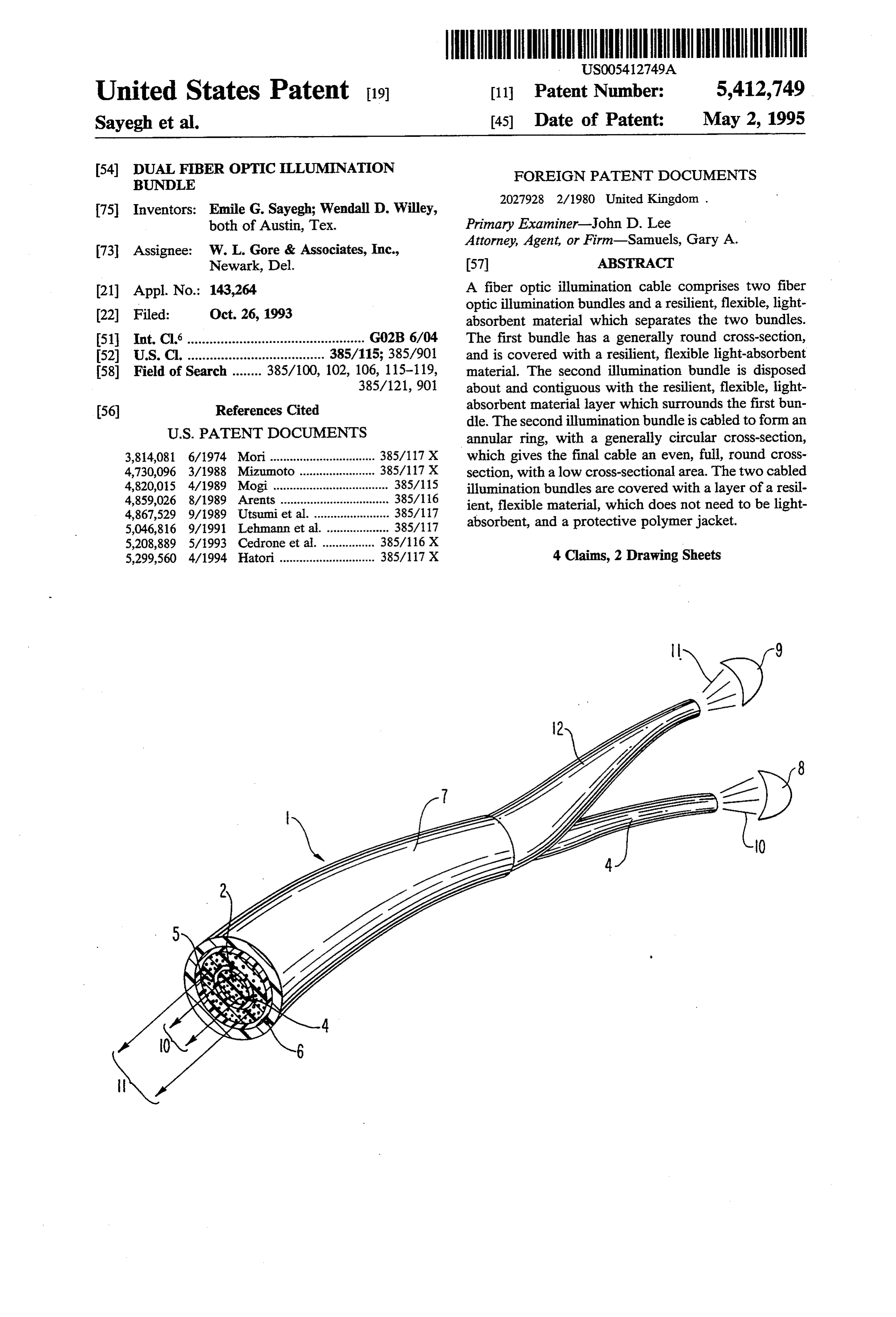
United States Patent 19 11 Patent Number: 5,412,749 Sayegh et al. 45) Date of Patent: May 2, 1995 54) DUAL FIBER OPTCLLUMINATION FOREIGN PATENT DOCUMENTS
BUNDLE
75 Inventors: Emile G. Sayegh; Wendall D. Willey, both of Austin, Tex. Primary Examiner-John D. Lee
Attorney, Agent, or Firm-Samuels, Gary A.
73 Assignee: W. L. Gore & Associates, Inc.,
Newark, Del. 57 ABSTRACT (21) Appl. No.: 143,264 A fiber optic illumination cable comprises two fiber optic illumination bundles and a resilient, flexible, light 22) Filed: Oct. 26, 1993 absorbent material which separates the two bundles. 51 Int. Cl................................................ G02B 6/04 The first bundle has a generally round cross-section, 52) U.S. Cl. ..................................... 385/115; 385/901 and is covered with a resilient, flexible light-absorbent 58) Field of Search ........ 385/100, 102, 106, 115-119, material. The second illumination bundle is disposed 385/121, 901 about and contiguous with the resilient, flexible, light (56) References Cited absorbent material layer which surrounds the first bun dle. The second illumination bundle is cabled to forman
3,814,081 6/1974 Mori................................ 385/117 X which gives the final cable an even, full, round cross 4,730,096 3/1988 Mizumoto ... 385/117 X section, with a low cross-sectional area. The two cabled 4,820,015 4/1989 Mogi ................................... 385/115 illumination bundles are covered with a layer of a resil 4,859,026 8/1989 Arents .. ... 38.5/116 ient, flexible material, which does not need to be light 4,867,529 9/1989 Utsumi et al. .... ... 385/117 absorbent, and a protective polymer jacket.
5,208,889 5/1993 Cedrone et al. .. ... 38.5/116X 5,299,560 4/1994 Hatori ............................. 385/117 X 4 Claims, 2 Drawing Sheets
Page 2
Drawing sheet — no readable text.
Page 3
Drawing sheet — no readable text.
Page 4
allow the coupling of light from one illumination bundle
DUAL FIBER OPTIC LLUMINATION BUNDLE to another.
FIELD OF THE INVENTION SUMMARY OF THE INVENTION
The cable of the invention provides a cable com
This invention relates to the field of fiber optics and 5 prised more specifically to fiber optic illumination bundles of two fiber optic illumination bundles and a soft, comprised of multiple fiber optic strands. flexible, light-absorbent material which separates the two bundles. The first bundle has a generally round
BACKGROUND OF THE INVENTION cross-section, and is covered with the soft, flexible light O absorbent material. This material is preferably at least
Fiber optic illumination bundles are commonly used one wrap of helically-wrapped, dark-pigmented ex to transmit light for illumination into restricted areas. panded polytetrafluoroethylene (PTFE) tape, such as Typical fiber optic illumination bundles are comprised carbon-loaded expanded PTFE. The use of expanded of many hundreds or thousands of individual fiber op PTFE with its low compressive modulus allows bend tics bunched together to form a single light-transmitting 15 ing of the illumination bundle with minimal loss due to bundle. Each fiber of the illumination bundle transmits micro-bending of the individual fibers of the illumina light individually through the principle of total internal tion bundle. Expanded PTFE can also withstand the reflection, while the full bundle efficiently transmits high temperatures generally required at the source end large amounts of light from a source to the area to be of the cable due to the heat generation of the light illuminated. Fiber optic illumination bundles find use in source. The second illumination bundle is disposed medical devices such as arthroscopic probes and cam about and contiguous with the soft, flexible, light eras, dental probes and cameras, and inspection probes absorbent material layer which surrounds the first bun for mechanical equipment. die. The second illumination bundle is cabled to form an Often it is necessary or desirable to have two separate annulus, with a generally circular cross-section, which fiber optic illumination bundles used together in close 25 gives the final cable an even, full, round cross-section, proximity to one another. It is generally advantageous with a low cross-sectional area. The two cabled illumi to position such separate illumination bundles in such a nation bundles are then covered with a layer of a soft, manner that they form one cable for ease of use and flexible material, which does not need to be light handling. One common method of accomplishing such absorbent. This material is preferably at least one wrap cabling is to individually jacket each bundle and twist 30 of helically-wrapped, expanded polytetrafluoroethyl one about the other, forming a twisted pair of illumina ene (PTFE) tape. The cable is then jacketed in a con tion bundles. This method produces a large cable, the ventional manner, such as by extrusion of a thermoplas tic polymer, or by the application of polymer shrink diameter being at least equal to the sum of the diameters tubes.
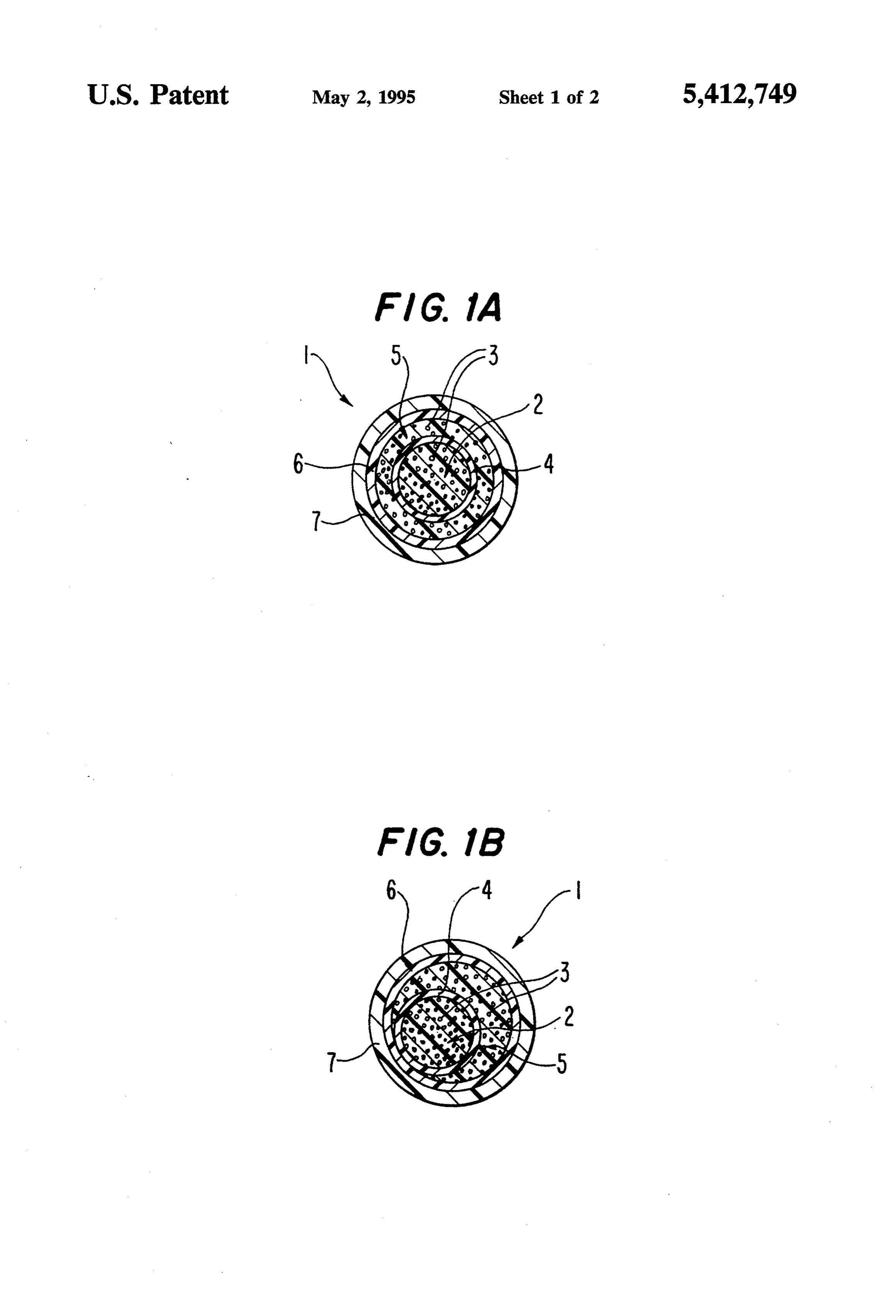
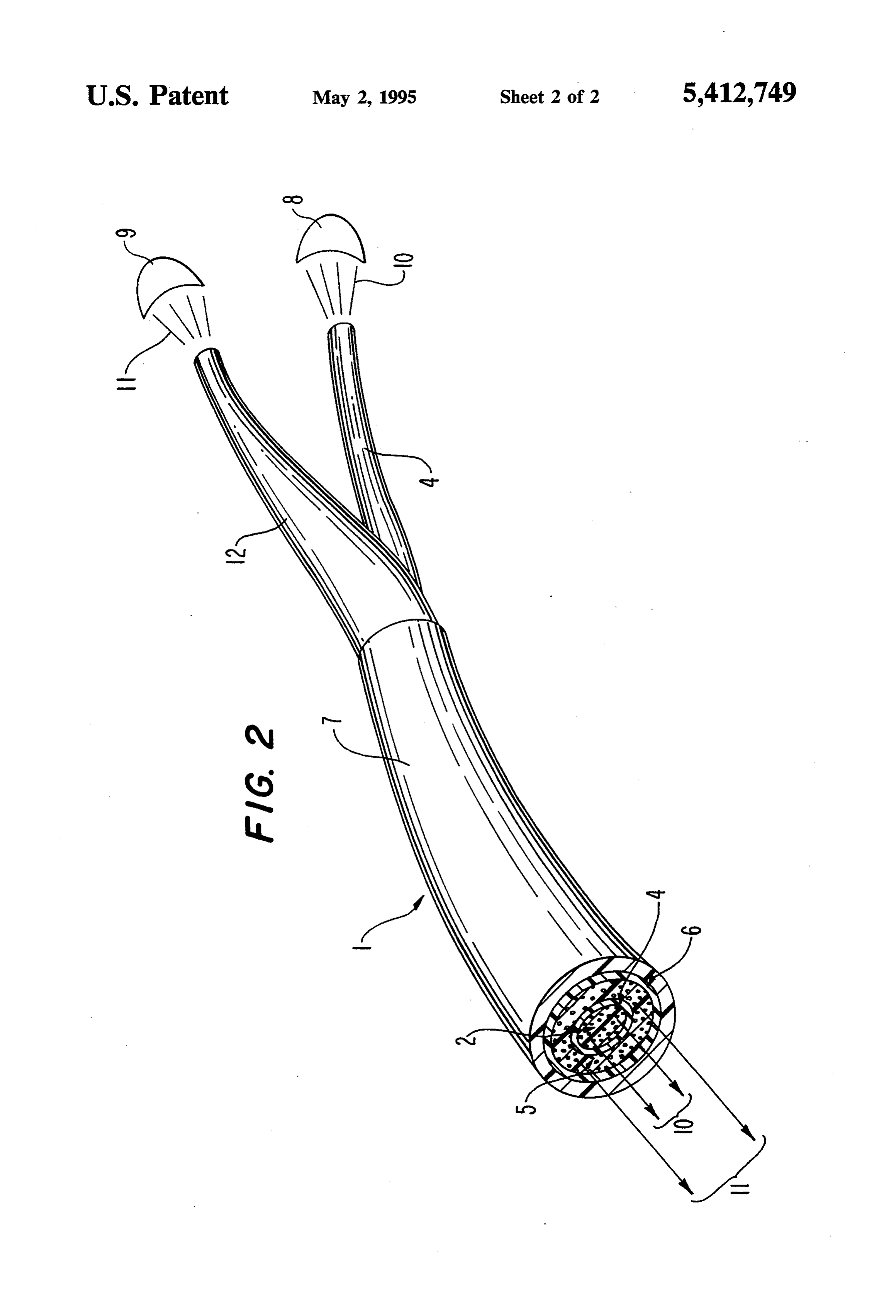
of the individually jacketed illumination bundles. The large diameter results in a lack of flexibility, excess 35 BRIEF DESCRIPTION OF THE DRAWINGS stress on the outer fiber optic strands, excess losses due FIGS. 1A and 1B show cross-sectional views of the to macrobending of the strands, as well as losses due to cable of the invention.
the extra fiber length required by the helical path of FIG. 2 shows a perspective view of the cable of the each bundle in the twisted construction. Another 40 method of cabling separate illumination bundles is to invention showing how the two illumination bundles jacket them as two pods of a flat cable, the jacket also are separated at the source end. forming a web between the pods. Again, such an ar DETAILED DESCRIPTION OF THE rangement results in a cable with a maximum cross-sec INVENTION tional dimension equal to at least twice the sum of the 45 The cable of the invention and processes for its manu diameters of the component illumination bundles. Also, facture are now described with reference to the draw such a cable is not as flexible and usable as a round cable. A third method of grouping two separate illumi ings to more fully and carefully delineate the compo nents and materials used in the invention, and how they nation bundles into one cable is to simply bunch the two are assembled.
illumination bundles into one large bundle, being care 50 FIGS. 1A and 1B show in cross-section views the ful to keep each component bundle separate at the ends cable 1 of the invention. A first fiber optic illumination for termination. This method results in a smaller cross bundle 2 is comprised of a plurality of fiber optic strands sectional area than the first two methods, but has one 3. Each fiber optic strand 3 is comprised of a silica glass major problem. When two illumination bundles are core covered with a cladding layer which has an index placed in contact with each other, light will be coupled 55 of refraction which is lower than that of the core. Such into one bundle from the other where the fiber optics of fiber optic strands are known in the art, and each strand the respective bundles are in contact with each other may or may not also have a coating layer over the down the length of the cable. This coupling is known in cladding. Such fiber optic strands may also be com the art as cross-talk. For bundles of reasonable size and prised of optically clear polymers such as polymethyl usable lengths, cross-talk results in appreciable amounts 60 methacrylate, AF Teflon available from DuPont, and of light leaving one bundle into the other. This loss of styrene. The first illumination bundle 2 is covered by a light from one bundle, and gain of unwanted light into soft, i.e. resilient, dark-pigmented polymer buffer layer the other is unacceptable, especially in applications 4. "Dark' colors are those that absorb light at the wave where the fiber optic bundles are used in light sensing length transmitted in the fiber optic strands, and gener easternetS. 65 ally includes dark brown, dark gray, and black. For The cable of the invention provides an improved example, layer 4 may be cigarette-wrapped or helically solution to these problems, by providing a highly flexi wrapped strips of porous expanded PTFE tape, which ble cable of low cross-sectional area which does not contains carbon black. The polymer buffer layer 4 is
Page 5
preferably selected from unsintered porous PTFE ma layer 4. A protective layer of polymer tubing 12 is used terials described in U.S. Pat. Nos. 3,953,566, 4,187,390, to protect the second fiber bundle 2 from the point 3,962,153 and 4,096,227 which have an expanded po where it separates from the first bundle 2. The ends of rous structure characterized by nodes and fibrils, the bundles 2 and 5 must be prepared and polished in ways disclosures of which are hereby incorporated by refer 5 known in the art. FIG. 2 shows that the light out of each ence. The carbon-filled strips are made by slitting out a bundle is a result of the transmission of light from each strip of selected width from a sheet of carbon-filled bundle's respective source only, and contains no light expanded PTFE. The carbon-filled sheet is prepared by which was coupled in from another source. a process described in U.S. Pat. No. 4,985,296. PTFE Although specific embodiments of the invention have films containing about 25%-85% by weight carbon are O been described and illustrated, it is to be understood that calendared or paste extruded from carbon containing modifications can be made without departing from the coagulated aqueous PTFE dispersions and stretched or scope and spirit of the invention. Such modifications expanded to yield films or sheets containing from about could include the use of high modulus strength member 3% to about 25% by weight carbon. The second fiber elements added to the cable, such as aramid fiber in optic illumination bundle 5 is then disposed about layer 15 stranded or braided form.
4 and is contiguous with layer 4 such that it at least We claim:
partially surrounds layer 4 and the first bundle 2. The 1. A dual fiber optic illumination bundle cable com second fiber optic illumination bundle 5 is also com prising:
prised of a plurality of fiber optic strands 3. It is not necessary that the second bundle 5 completely surround 20 (a)generally a first fiber optic illumination bundle having a round cross-section, said first fiber optic the first bundle 2 and layer 4. FIG. 1A shows a cable illumination bundle being comprised of a plurality where the second bundle 5 completely surrounds first of fiber optic strands, each of said fiber optic bundle 2 and layer 4. FIG. 1B shows a cable where the strands comprising in order a core and a cladding second bundle 5 does not completely surround first layer;
bundle 2 and layer 4. Note that in both FIG. 1A and 25 (b) a dark-pigmented resilient polymer layer sur FIG. 1B the final cable is of generally round cross-sec rounding and contiguous with said first fiber optic tion. A protective soft, i.e. resilient, binder 6 is applied illumination bundle;
over second bundle 5. The binder 6 is preferably com (c) a second fiber optic illumination bundle disposed prised of at least one cigarette-wrapped or helically about and at least partially surrounding said dark wrapped strip of expanded PTFE. The material used 30 pigmented polymer layer, said second fiber optic for the binder 6 is preferably the same material used for illumination bundle being comprised of a plurality the dark-pigmented polymer buffer layer 4, however, binder 6 does not need to be dark-pigmented. Other of fiber optic strands just as said first fiber optic soft, resilient materials may be used for binder 6 such as illumination bundle;
fabrics such as woven cotton, or non-woven felts. The 35 (d) a resilient polymer layer surrounding and contigu cable is then enclosed in a protective polymer jacket 7 ous with said second fiber optic illumination bun which should be flexible, and is made from any of the dle; and materials commonly used in the art for jacketing cables, (e) a flexible protective polymer jacket surrounding such as polyvinyl chloride, polyethylene, polyurethane, and contiguous with said last mentioned resilient rubber, silicone, polyester elastomers, and polymeric 40 polymer layer.
fluorocarbons such as fluorinated ethylene propylene, 2. The cable of claim 1 wherein said dark-pigmented perfluorinated alkyl vinyl ether polytetrafluoroethylene polymer layer is comprised of carbon-filled expanded and expanded polytetrafluoroethylene. porous polytetrafluoroethylene. FIG. 2 shows the cable of the invention 1 in perspec 3. The cable of claim 2 wherein said resilient polymer tive view. This view shows how first and second light 45 layer of element (d) is comprised of expanded porous sources, 8 and 9 respectively, illuminate the first illumi polytetrafluoroethylene.
nation bundle 2 and the second illumination bundle 5 4. The cable of claim 1 wherein said protective poly separately and independently. Light 10 from source 8 merjacket is made of material selected from the group enters and exits the first illumination bundle 2. Light 11 consisting of polyvinyl chloride, polyethylene, polyure from source 9 enters and exits the second illumination thane, rubber, silicone, polyester elastomers, and poly bundle 5. The first fiber optic illumination bundle 2 is meric fluorocarbons.sk ck s:
covered with a layer of dark-pigmented polymer buffer
Provenance
- Collection
- Cited prior art
- Original PDF
- patentimages.storage.googleapis.com →
- Filed
- 1993-10-26
- Pages
- 5
- Method
- pdftotext (the PDF's own text layer) + pdftoppm 300dpi page scans
- Source
- Google Patents bibliographic record
- Granted
- 1995-05-02
- Inventors
- Emile G. Sayegh; Wendall D. Willey; WL Gore and Associates Inc
- Transcribed from
- patentimages.storage.googleapis.com →