patent · US6195016
Fiber optic display system with enhanced light efficiency
27 February 2001
Page 1 — bibliographic record
(12) United States Patent (10) Patent No.: US 6,195,016 B1 Shankle et al. 45) Date of Patent: *Feb. 27,9 2001
(54) FIBER OPTIC DISPLAY SYSTEM WITH 4,762,392 8/1988 Yamamoto et al. ................. 385/141 ENHANCED LIGHT EFFICIENCY 4,773,730 9/1988 Sedlmayr ............................. 385/137 4,786,139 11/1988 Sedlmayr ... ... 385/120 (75) Inventors: Matthew W. Shankle, Denver, CO 2.
aCKO C a
S. SE k Hastics S. f even J. Shan Kle, Redmond, both O
WA (US) 4,917,448 4/1990 Oppenheimer . . 385/116 4929,048 5/1990 Cuypers ....... ... 385/116 (73) Assignee: Advance Display Technologies, Inc., 4.950,357 8/1990 Sedlmayr . . . 156/426 Englewood, CO (US) 4,973,128 * 11/1990 Hodges ... ... 359/41 5,009,475 4/1991 Knudson .. ... 385/133 ( c: ) Notice: Subject to any disclaimer, the term of this 5,013,110 5/1991 Marazzi ........... ... 385/77 patent is extended or adjusted under 35 5,058,989 10/1991 Sakunaga et al. 359/455 U.S.C. 154(b) by 0 days. 5,129,032 7/1992 Kawai et al. ........ ... 385/76 5,247,600 * 9/1993 Williams et al. ...................... 385/15
This patent is Subject to a terminal dis (List continued on next page.)
claimer.
Primary Examiner Donnie L. Crosland (21) Appl. No.: 09/384,652 (74) Attorney, Agent, or Firm McAndrews, Held & Malloy, Ltd.
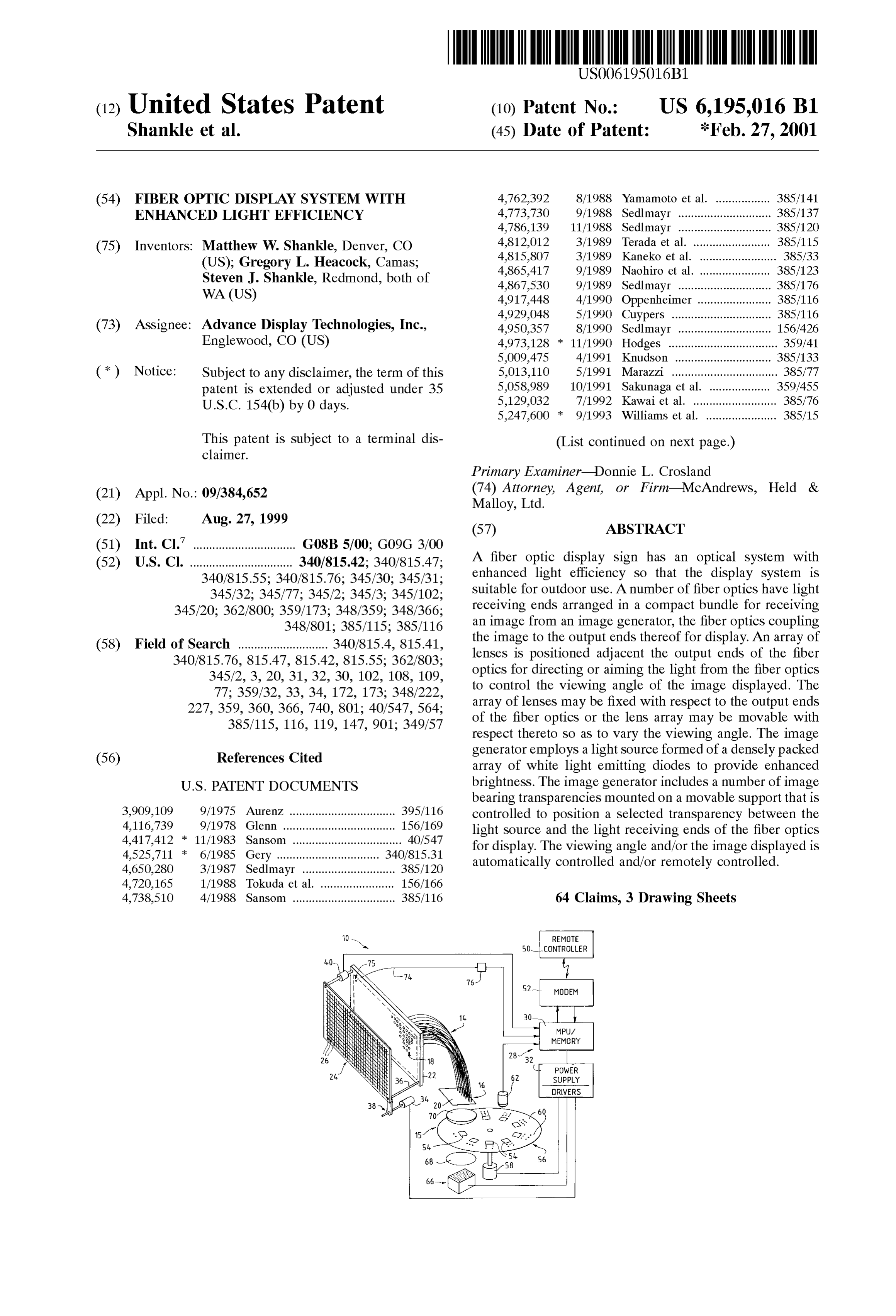
(22) Filed: Aug. 27, 1999 (57) ABSTRACT (51) Int. Cl." ................................ G08B 5700; G09G 3/00 (52) U.S. Cl. ................................ 340/815.42; 340/815.47; A fiber optic display sign has an optical System with 340/815.55; 340/815.76; 345/30; 345/31; enhanced light efficiency So that the display System is 345/32: 345/77; 345/2; 345/3; 34.5/102; suitable for outdoor use. A number of fiber optics have light 345/20; 362/800; 359/173; 348/359; 348/366; receiving ends arranged in a compact bundle for receiving 348/801; 385/115; 38.5/116 an image from an image generator, the fiber optics coupling (58) Field of Search ............................ 340/815.4, 815.41, the image to the output ends thereof for display. An array of 340/815.76, 815.47, 815.42, 815.55; 362/803; lenses is positioned adjacent the output ends of the fiber 345/2, 3, 20, 31, 32, 30, 102, 108, 109, optics for directing or aiming the light from the fiber optics 77; 359/32, 33, 34, 172, 173; 348/222, to control the Viewing angle of the image displayed. The 227,359, 360, 366, 740, 801; 40/547, 564; array of lenses may be fixed with respect to the output ends 385/115, 116, 119, 147, 901; 349/57 of the fiber optics or the lens array may be movable with respect thereto So as to vary the Viewing angle. The image (56) References Cited generator employs a light Source formed of a densely packed array of white light emitting diodes to provide enhanced
bearing transparencies mounted on a movable Support that is 3,909,109 9/1975 Aurenz ................................. 395/116 controlled to position a Selected transparency between the 4,116,739 9/1978 Glenn ..... ... 156/169 light Source and the light receiving ends of the fiber optics 4,417,412 11/1983 Sansom .................................. 40/547 for display. The viewing angle and/or the image displayed is 4,525,711 * 6/1985 Gery ........... 340/815.31 automatically controlled and/or remotely controlled. 4,650,280 3/1987 Sedlmayr ............................. 385/120 4,720,165 1/1988 Tokuda et al. ....................... 156/166 4,738,510 4/1988 Sansom ................................ 385/116 64 Claims, 3 Drawing Sheets
REMOTE
SOCONTROLLER
MODEM
MPUA
MEMORY
SUPPLY
DRIVERS
Page 2
Drawing sheet — no readable text.

Page 3
Drawing sheet — no readable text.
Page 4
Drawing sheet — no readable text.
Page 5
Drawing sheet — no readable text.
Page 6
FIBER OPTIC DISPLAY SYSTEM WITH with the present invention, an array of lenses is positioned ENHANCED LIGHT EFFICIENCY adjacent the Second ends of the fiber optics for receiving light therefrom wherein the lenses aim the light output from
CROSS-REFERENCE TO RELATED the fiber optics to control the viewing angle of the image APPLICATIONS displayed. The lens array of the present invention Substan N/A tially eliminates unwanted reflections back into the fiber optics and is extremely light efficient. Moreover, the position
STATEMENT REGARDING FEDERALLY of the lens array with respect to the Second or output ends of SPONSORED RESEARCH OR DEVELOPMENT the fiber optics can be controlled to provide a desired Viewing angle of the image displayed.
N/A In one embodiment of the present invention, the lens array TECHNICAL FIELD is formed as a panel of microlenses. In this embodiment, the array is movable with respect to the output ends of the fiber
The present invention is directed to a fiber optic display optics to vary the viewing angle of the image displayed. The System and more particularly to a fiber optic display System 15 position of the lens array is automatically controlled in with enhanced light efficiency that is Suitable for traffic Signs accordance with data Stored in a computer control unit of the or the like used outdoors. display System. The display System includes a communica tion interface Such as a modem or a wireleSS communication
BACKGROUND OF THE INVENTION interface coupled to the System's computer control unit to allow the positioning of the lens array to be remotely
Large fiber optic displays are known in which the light controlled.
receiving ends of the fiber optics are arranged in a bundle adjacent a Small LCD display to pick up the image displayed In a Second embodiment of the present invention, a panel thereon. The fiber optics couple the image to the light output that Supports the Second or output ends of the fiber optics ends of the fibers to display an enlarged image. The image 25 also Supports an individual lens in association with each output from the fiber optics is enlarged by spacing the light fiber optic. The positioning of the lens with respect to a fixed output ends of the fiber optics farther apart than the Spacing aperture associated with the fiber optic output end controls between the light receiving ends of the fiber optics. Such the viewing angle of the displayed image. Moreover, by fiber optic displays are difficult to use outdoors in bright utilizing a prismatic lens, the image may be directed to a light conditions because they are very light inefficient. For particular location. When the fiber optic display is utilized to example, only approximately 2% of the backlight typically display traffic sign information, the prismatic lens can direct passes through a LCD panel. In order to control the viewing the image to a particular lane of traffic and to a particular angle of the displayed images, the output ends of the fiber location So that the image is Seen by only the vehicle drivers optics in Some known displays have been cut at a very Sharp to whom the information is directed. angle. However, these types of fiber optic displays have 35 To further increase the brightness of the fiber optic problems with unwanted reflections of light back into the display, a light Source is employed that is formed of a fibers. Another known fiber optic display employs a diffu densely packed array of white light emitting diodes. In one Sion face plate Spaced a distance from the fiber optic output embodiment, the light emitting diodes are mounted on one ends. The diffusion plate spreads the light output from the or more walls of a white interior illumination box. The light fiber optics. However, because a diffusion plate does not aim 40 from the illumination box passes through a brightness or direct the light but randomly Scatters light, it is not light enhancing film to a frosted plate So as to produce extremely efficient and further reduces the light output of the display. bright but uniform white light illumination. Moreover, the back light for the input image generator is In accordance with another feature of the present typically a Single element bulb. So as to provide a uniformly invention, the fiber optic display System includes one or illuminated input image. However, given the light ineffi 45 more “monitoring fiber optics having an end Supported in ciencies of known fiber optic display Systems, it is difficult the output display panel for receiving ambient light. These to find a backlight with sufficient brightness to allow the “monitoring fiber optics couple received ambient light to a fiber optic display to be used outdoors in ambient light photo detector that is in turn coupled to a controller. Based conditions. on the intensity of the ambient light as determined by the BRIEF SUMMARY OF THE INVENTION 50 photo detector, the controller varies the brightness of the illumination Source. Under bright ambient light conditions,
In accordance with the present invention, prior fiber optic Such as daylight, the controller increases the brightness of display Systems have been overcome. The fiber optic display the illumination Source; whereas at night, the brightness of System of the present invention utilizes optical elements that the illumination Source can be decreased. Moreover, the increase the light efficiency and the light throughput of the 55 detected light intensity can be monitored to determine if the fiber optic display So that it is Suitable for use outdoors. face of the fiber optic display is dirty. This information can More particularly, the fiber optic display system of the then be transmitted via the communication interface to a present invention includes a plurality of fiber optics having remote location So as to provide notice that the display needs first and Second ends, the first ends being arranged in a cleaning.
bundle to receive an image. The fiber optics couple the 60 In accordance with a further feature of the present received image to the Second ends thereof for displaying the invention, the input image generator includes a number of image where the Spacing between the Second ends of the image bearing transparencies on a movable Support. A motor fibers is greater than the Spacing between the first ends of the is coupled to the transparency Support and controlled to fibers. The display System also includes a light Source and an move the Support to position a Selected image bearing image generator disposed between the light Source and the 65 transparency between the light Source and the first or input first ends of the fiber optics to generate an image that is ends of the fiber optics So as to display the image depicted focused on the first ends of the fiber optics. In accordance on the Selected transparency. Each of the image bearing
Page 7
transparencies is accompanied by position indicia that is of different languages or the Sign can display a Series of detected So as to provide position feedback and/or registra messages in a particular Sequence. Moreover, the image or tion information for the controller. The controller is pro images Selected for display can be changed and/or remotely grammed to display Selected images in a particular Sequence controlled. Thus, if an accident occurs down the road from and/or at particular times during the day. Moreover, the the sign, the Sign can be remotely controlled to periodically controller can receive information from a remote location to display a warning message instead of or in addition to the change the image displayed or the Sequence of images message the Signal typically displayS. Further, for a speed displayed. The image generator of the present invention is limit sign, the Speed limit displayed can be remotely extremely simple and robust but allows great flexibility so changed in accordance with weather and/or road conditions. that different images can be depicted on the fiber optic Thus, the fiber optic display System of the present invention display. provides an extremely flexible outdoor sign. These and other advantages and novel features of the includes As shown in FIG. 2, the fiber optic display system 10 present invention, as well as details of an illustrated embodi have lighta large number of fiber optics 14. The fiber optics receiving ends 16 arranged to receive an image ment thereof, will be more fully understood from the fol from an image generating System 15 as discussed in detail lowing description and drawings. 15 below. The image picked up by the fiber ends 16 is coupled
BRIEF DESCRIPTION OF THE SEVERAL by the fiber optics 14 to light output ends 18 for display. A VIEWS OF THE DRAWINGS fiber optic input panel 20 Supports the light receiving ends 16 of the fiber optics 14 in a compact bundle; whereas a fiber
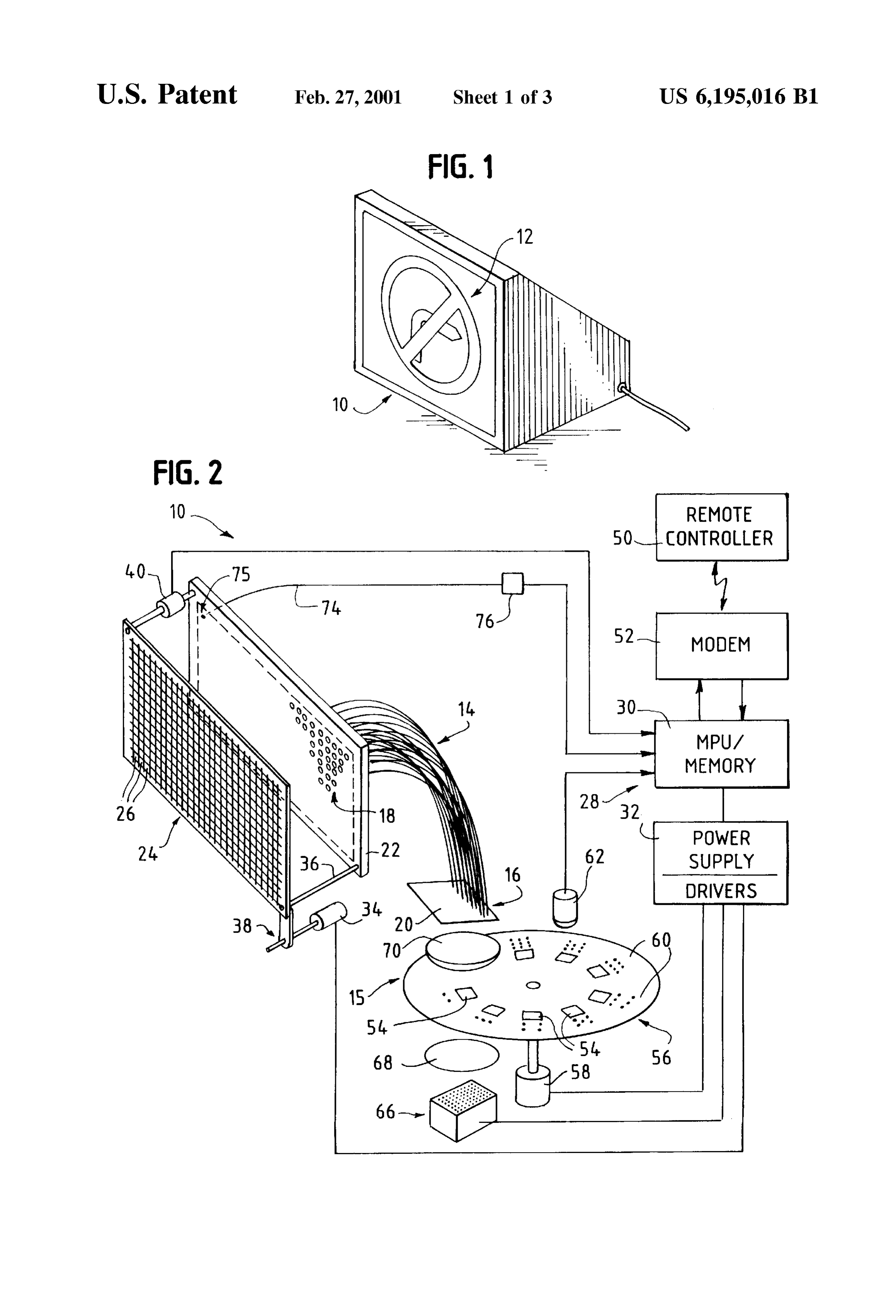
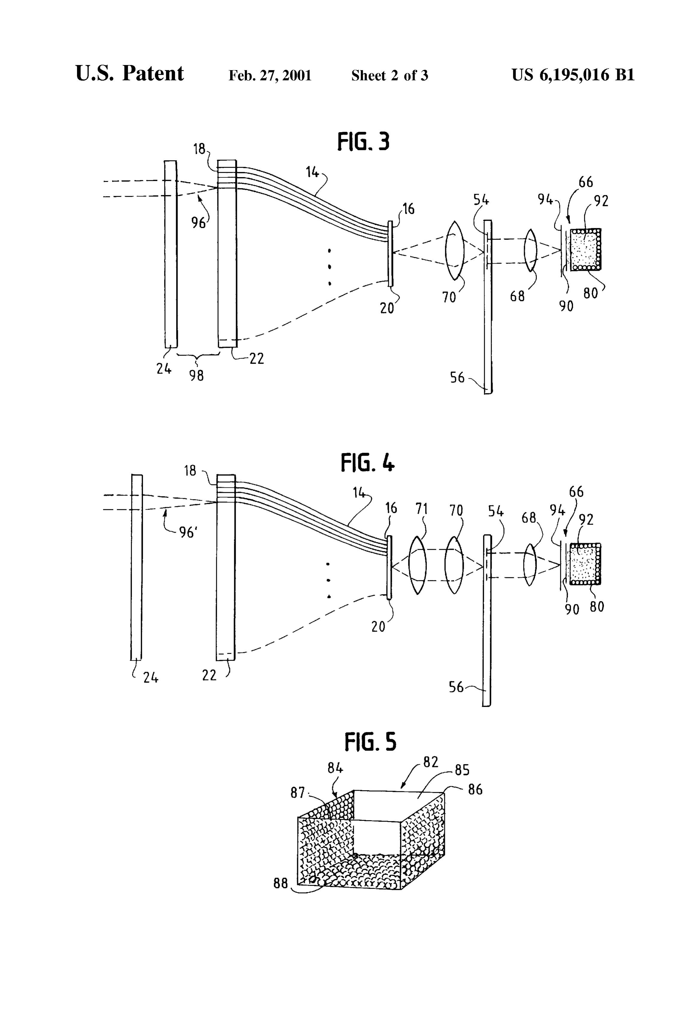
FIG. 1 is a perspective view of a fiber optic display in optic output panel 22 Supports the light output ends 18 of the accordance with the present invention; fibers 14. The spacing between the fiber ends 18 Supported FIG. 2 is a block diagram illustrating one embodiment of in the panel 22 is greater than the Spacing between the light the fiber optic display System of the present invention receiving ends 16 Supported in the panel 20 to generate an utilizing a microlens array that is movable with respect to the enlarged image at the output 18 of the fiber optics. The fiber optic output panel; 25 position of the fiber ends 16 in the input panel 20 is FIG. 3 is a ray tracing illustrating the optics of the fiber correlated with the position of the fiber ends 18 in the output optic display system of FIG. 2; panel 22 So that the Segment of the image picked up by each FIG. 4 is a ray tracing illustrating the optics of the fiber of the input fiber ends 16 is displayed in the corresponding, optic display system of FIG. 2 with the lens array moved a the fiberposition correct optics at the fiber optic output panel 22. Preferably, employed are plastic optical fiberS Such as greater distance from the fiber optic output panel than as PMMA fiber optics. As an example, the size of the fiber optic shown in FIG. 3; input panel 20 is on the order of 57 mm square whereas the FIG. 5 is a perspective view of a preferred embodiment of fiber optic output panel 22 is on the order of 450 mm Square a light Source used with the image generator of the fiber with a 6 mm pixel pitch and fiber diameter of 0.75 mm. optic display System; 35 Obviously, the size of the input panel and output panel can FIG. 6 is a cross-sectional view of the fiber optic output vary as well as the fiber diameter and spacing. Further, it panel in accordance with a Second embodiment of the should be appreciated that fiber optics other than plastic present invention with an individual lens associated with fibers can be used as well.
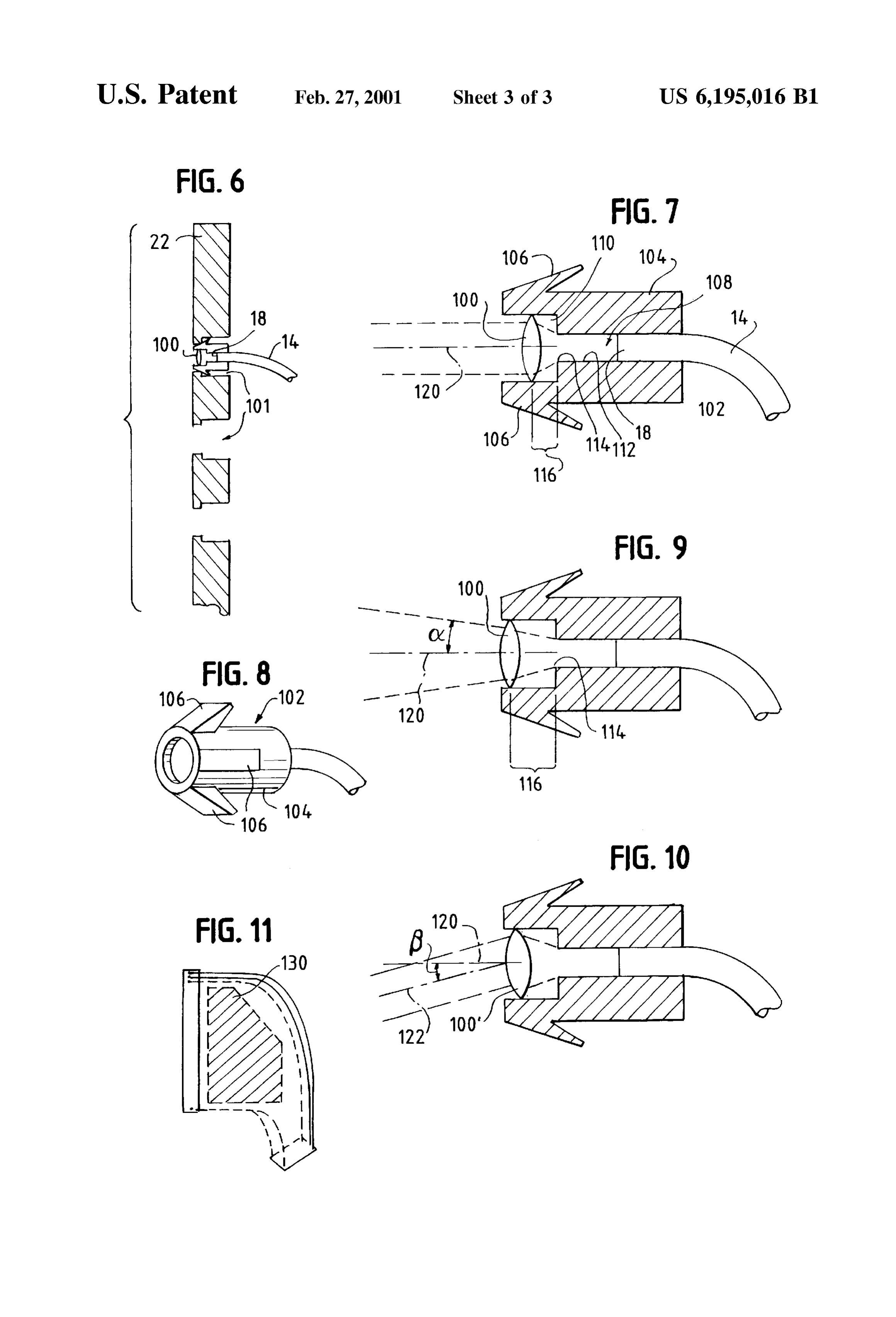
each fiber optic output end used for the display; The fiber optic display system 10 in accordance with the FIG. 7 is a cross-sectional view of a fiber optic end and 40 present invention includes an array of lenses for aiming the lens Support member to control the exit angle of the light light output from the fibers So as to control the exit angle of from the display; the light or viewing angle of the displayed image. In a first FIG. 8 is a perspective view of the fiber optic end and lens embodiment as shown in FIG. 2, the array of lenses is in the support member of FIG. 7; form of a plate or panel 24 of lenses 26. Preferably, the FIG. 9 is a cross-sectional view of the fiber optic end and 45 lenses
The 26 are microlenses embossed on a sheet of plastic.
light output from one fiber optic 14 is picked up by one lens Support member with the lens moved a greater distance or more adjacent microlenses that collect and aim the light from a fixed aperture associated with the fiber end than as to control the Viewing shown in FIG. 7 so as to diverge the light output from the so that a viewer of theangle. The Viewing angle is controlled display 10 has to be in a particular lens; 50 position relative to the display in order to view the image. AS FIG. 10 is a cross-sectional view of the fiber end and lens
Support member illustrating the effect of utilizing a prismatic Such, although the display 10 may be widely Seen, the image depicted thereon can be directed to viewers in a particular lens, and location. Thus, for a traffic sign, the message can be directed FIG. 11 is a cross-sectional view of the fiber optics to vehicle drivers in a particular lane of traffic as opposed to Supported in an expanded polyurethane foam material So as 55 all of the lanes.
to provide a structurally robust fiber optic display System. Preferably, the lens array 24 is movable with respect to the DETAILED DESCRIPTION OF THE fiber optic output panel 22 So that the Viewing angle can be INVENTION automatically changed by a controller 28. The controller 28 includes a computer control unit 30 with a microprocessor or
The fiber optic display system 10 of the present invention 60 CPU and associated memory. The controller 28 also includes as shown in FIG. 1 displays a large color image 12 of a power Supply and driver generally designated 32 that is enhanced brightness So as to be Suitable for outdoor use and coupled between the computer control unit 30 and one or in particular, for use as a traffic sign. AS discussed in detail more motors such as the servo motor 34. The servo motor 34 below, the display 10 can display any one of a number of is responsive to control Signals coupled from the computer images. A number of images can be displayed in a prede 65 control unit 30 via the driver unit 32 to slide the lens array termined Sequence or at particular times during the day. For 24 towards or away from the fiber output panel 22. The lens example, the traffic Sign can display a message in a Sequence array panel 24 slides on one or more pins 36 wherein the
Page 8
S 6 motor 34 is coupled to the lens array panel 24 via a lead ency 54 and the fiber optic input panel 20 focuses the image Screw 38 or the like. on the input ends 16 of the fiber optics 14 for display at the A position sensor 40 provides feedback information to the output 18 of the fibers. The computer control 30 controls the computer control unit 30 regarding the current position of motor 58 to position selected ones of the transparencies 54 the lens array panel 24 with respect to the fiber optic panel in a desired Sequence as determined by data Stored in the 22. It is noted however, depending upon the type of motor computer control unit's memory. The memory of the com 34 utilized and the information stored in the computer puter control unit 30 storing the identity of the sequence of control unit, a position Sensor 40 might not be necessary. images to be displayed is preferably electronically program The computer control unit 30 is responsive to data repre mable So as to be updated or changed by data received from Senting the current position of the lens array panel 24 with the remote controller 50. Although the content of the images respect to the fiber optic panel 22 to provide position control depicted on each of the transparencies 54 is fixed, the signals to the motor 34 via the driver unit 32 so as to position movable support 56 can support a sufficient number of the lens array 24 to provide a desired viewing angle. The transparencies with different images thereon So as to display computer control unit 30 automatically changes the position different messages on the display 10 depending on various of the lens array 24 with respect to the fiber optic plate 22 15 circumstances.
in accordance with data Stored in its memory and/or in It is noted that an emissive light display may also be used accordance with information received from a remote con as the image generating System 15. In this embodiment, the troller 50. For example, when displaying one selected computer control unit 30 directly controls the image, picto image, one viewing angle may be used to direct the message rial and/or text, generated wherein the images are not fixed to a first location. However, a different message can be or limited to a predetermined number.
directed to a different location by changing the position of The computer control unit 30 also transmits maintenance the lens array and the Viewing angle. Thus, the viewing and/or status information to the remote controller 50 regard angle can be controlled to change when different messages ing the operation of the fiber optic display 10. For example, are displayed. one or more “monitoring” fiber optics 74 are employed to Preferably, the fiber optic display system 10 includes a 25 pick up ambient light the intensity of which is detected by communication interface Such as a modem 52 or a wireleSS a photo detector such as a photo diode 76. Preferably, an end communication interface So as to receive data from a remote 75 of the fiber optic 74 is supported in the output panel to controller 50 and/or to send status information to the remote receive ambient light. The photo detector 76 detects the controller 50. Thus, the viewing angle of the fiber optic intensity of the received light and generates a Signal repre display system 10 can be remotely controlled as well as the Sentative thereof that is coupled to the computer control unit image 12 or images Selected for display as discussed below. 30. The computer control unit 30 is responsive to the The image generator System 15 allows one of a number of intensity of the ambient light to control the intensity of the predetermined images to be depicted on the fiber optic light Source 66. The brighter the ambient light, the greater display 10. In particular, the image generator includes a the intensity of the light Source. Therefore, in response to the number of image bearing transparencies 54 on a movable 35 intensity of the ambient light as detected by the photo support 56. The transparencies are preferably formed of a detector 76, the computer control unit 30 via the power glass plate or the like with a transparent color image printed supply unit 32 varies the brightness of the light source 66. thereon. The movable support as shown in FIG. 2 is in the The intensity of the light picked up by the monitoring fiber form of a disk with the transparencies 54 arranged about a 74 is also used to determine whether there has been dirt circle on the disk. It should be appreciated however that the 40 build-up on the exterior surface of the display 10. If the Support can take forms other than a disk (for example, a computer control unit 30 determines from monitoring the rotatable drum) as long as the Support can be moved to Select intensity of the ambient light over a given period of time that a particular image for display. The disk 56 is rotatable by a the display 10 needs to be cleaned, the controller 30 trans motor such as the servo motor 58 that is controlled by the mits status information to the remote controller 50 so that the computer control unit 30 via the power supply and driver 45 fiber optic display System can be properly maintained. It is unit 32. Each image bearing transparency 54 has position or noted that the Status information can be retrieved or Sent to registration indicia 60 associated therewith to uniquely the remote computer whenever desired.
identify the transparency. The position indicia 60 is detected The optical system of the fiber optic display 10 of the by an indicia detector 62 that is in a known position with present invention is illustrated in FIG. 3. As shown therein, respect to the display position of a Selected image, i.e. the 50 the light Source 66 preferably includes an array of densely position of a Selected transparency between the light Source packed white light emitting diodes (LEDs). In a preferred 66 and the fiber optic panel 20. The indicia detector 62 embodiment as shown in FIG. 5, the array of LEDs are decodes the indicia into digital information which is pro mounted on one or more inner Surfaces of a box 82 having vided to the computer control unit 30. It is noted that, the a white interior for reflecting light therein. In one indicia 60 and indicia detector 62 can be any of a well 55 embodiment, the LEDs are mounted on the inner Surfaces of known number of types. For example, the indicia might be the four side walls 84–87 and the bottom wall 88 of the box in the form of a barcode and the indicia detector 62 can be 82. As an example, 120 LEDs are mounted on each 65 mm a barcode Scanner or the like. Square wall. However, it should be appreciated that the The computer control unit 30, in response to position number of LEDs and size of the walls can vary. Further, the information received from the indicia detector 62 controls 60 LEDs can be mounted on a reduced number of the interior the motor 58 to position a Selected image bearing transpar side walls and/or the bottom wall 88. The white Surface of ency 54 between a light source 66 and the fiber optic input the interior of the box 82 wherever an LED is not mounted panel 20. A lens 68 gathers the light from the source 66 and reflects the white light from the LEDs to provide an concentrates the light on the Selected image bearing trans extremely bright light Source. A brightness enhancing film parency 54 So as to project the image borne on the trans 65 90 such as made by the 3M Company is positioned in front parency 54 to the input ends 16 of the fiber optics 14. A lens of the opening 92 of the box 82 adjacent the top of the side 70 disposed between the Selected image bearing transpar walls 84-87 to further enhance or increase the brightness of
Page 9
the lightSource. Afrosted glass plate 94 is positioned in front member 104 is inserted into an aperture 101 of the fiber optic of the brightness enhancing film. Through multiple reflec output panel 22, the arms 106 are pushed inward, locking the tions of the light within the white box 82, the use of multiple member 104 in the aperture 101 of the panel 22. The LEDs and the brightness enhancing film 90, the box 82 acts member 104 includes a first aperture 108 into which the end as a light integrator which, when used in conjunction with 18 of a fiber optic is inserted. The aperture 108 leads into a the frosted glass plate 94 produces even or uniform white larger aperture 110 in which is mounted the lens 100. Light illumination light. If one or even multiple LEDS go out, the exiting the end 18 of the fiber optic 14 is blocked by the wall light Source 66 is Still operational because the reflection of 112 defining the aperture 108. The shoulder 114 of the wall the light within the box 82 will mask out the non-operational 112 acts like a fixed optical aperture So that it does not matter LEDs. Further, the computer control unit 30 monitors the how far the end 18 of the fiber optic extends into the aperture Status of the light Source 66 to determine if a predetermined 108. The optical aperture at 114 remains the same. The number of LEDs are non-operational So as to indicate that projection of light from the fixed aperture 114 is collected by the light Source 66 needs to be replaced. If a predetermined the lens 100. The lens 100 can be a spherical lens having a number of LEDs are non-operational, the computer control focal length of 3 to 8 mm. With the lens 100 positioned in unit sends an indication thereof to the remote controller 50 15 the member 104 at a distance 116 approximately equal to in a Status message. one focal length from the fixed aperture 114, the light exiting the lens 100 is nearly parallel with respect to the optical
Aspherical lens 68 has a focal length of approximately 30 center mm to collimate the light at any point on the plate 94 to farther line from 120 of the lens 100. If the lens 100 is moved the fixed aperture 114, as shown in FIG. 9, so direct the light to the back of the image bearing transparency that the distance 54. Any point on the transparency 54 is focused on the fiber lens 100, the angle116C. isofgreater the than one focal length of the exiting light becomes diverging optic input plate 20 by the lens 70. The fiber optics 14 couple relative to the optical center line 120. the image received by the input ends thereof to the output exiting light in a particular direction, i.e.Intoorder to direct the the right or to the ends 18 of the fibers. The image at the output of each fiber left, etc., the lens 100' is formed as a prismatic lens as shown end 18 diverges as shown by rays 96 until the rays intersect in FIG. 10. With the prismatic lens 100, the center line of the the lens array 24. Each of the microlenses of the array 24 has 25 illumination 122 is tilted by an angle f with respect to the a focal length of 3 to 35 mm and acts to collect the light and normal center line 120.
direct it to a viewer in a particular viewing area. By changing the Spacing between the lens array 24 and the fiber optic input After inserting the fiber ends 18 and 16 into the respective output panel 22, the viewing angle presented to the viewer extremely and output panels 20 and 22, in order to form an is correspondingly changed. For example, if the lens array robust display System, polyurethane foam 130, as 24 is composed of lenses each having a focal length of 10 shown in FIG. 11, is inserted into a mold surrounding the fibers. The polyurethane mm with the lens array 24 located 10 mm from the fiber expands as it sets, Separating foam flows around the fibers and optic output panel 22, shown by the spacing 98 in FIG.3, the rub the fibers So that they do not resulting viewing angle will be narrow with concentrated together scratching each other. The foam provides a fiber brightness, much like a flashlight beam. If the lens array 24 35 optic Structure that can withstand impacts to which outdoor is moved farther from the fiber optic output panel 22 as Signs are typically exposed.
shown in FIG. 4, the image viewing angle will be expanded The fiber optic display System of the present invention has as the light output from the fiber ends 18 diverges as shown an optical System that provides enhanced brightness of the by the rays 96" until the rays intersect the lens array 24. In output light. AS Such, the display System 10 can be used for this case, a diverging viewing angle is produced, Similar to 40 outdoor Signs. Although the fiber optic display System 10 is the light from a lantern which has a much greater viewing Structurally robust with a simple, low-cost image generator, angle than the light from a flashlight. It is noted that the use it is extremely flexible and allows the displayed image of microlenses in an array that moves is advantageous changed. and/or view angle to be automatically and/or remotely because there is not a one to one association between a microlens and a fiber optic. AS the array 24 moves farther 45 Many modifications and variations of the present inven from the panel 22, a given microlens will receive light from tion are possible in light of the above teachings. Thus, it is more fibers. In other embodiments that utilize a lens array to be understood that, within the Scope of the appended wherein each fiber has a particular, associated lens, that claims, the invention may be practiced otherwise than as relationship should be maintained as the lens array 24 is described hereinabove.
moved. It is further noted, that multiple lenses may be used 50 What is claimed and desired to be secured by Letters to focus the image borne on the transparency 54 onto the Patent is:
ends 16 of the fiber optic input panel 20 such as shown by 1. A fiber optic display System comprising: lens 70 and lens 71 in FIG. 4. a plurality of fiber optics having first and Second ends, the In an alternative embodiment, instead of a movable lens first ends being arranged in a bundle to receive an array 24, or in addition thereto, each fiber optic end 18 for 55 image, the fiber optics coupling an image to the Second displaying the image has an associated lens 100. AS shown ends thereof for displaying the image wherein the in FIG. 6, the fiber optic output panel 22 has a number of spacing between the Second ends of the fiber optics is apertures 101 therein and in which the fiber optic output end greater than the Spacing between the first ends in the 18 and the lens 100 are supported. Although the fiber optic bundle;
end 18 and the lens 100 can be directly mounted in the 60 an image generator that generates an image received by aperture 101 of the panel 22, preferably, the fiber end 18 and the first ends of the fiber optics; and lens 100 are mounted in a focus mounting member 102 an array of lenses for receiving light from the Second ends which is inserted into an aperture 101 of the panel 22. The of the fiber optics, the lenses aiming the light from the mounting member 102 for the fiber end 18 and associated fiber optics to control the Viewing angle of the image lens 100 as shown in FIGS. 7 and 8 includes a cylindrical 65 displayed.
body 104 with a number of arms 106 extending outwardly 2. A fiber optic display System as recited in claim 1 from an upper peripheral surface of the body 104. When the wherein Said array of lenses includes a sheet of microlenses.
Page 10
3. A fiber optic display System as recited in claim 1 asSociated with the fiber optic, the Second aperture wherein Said array of lenses is movable with respect to the being of greater Size than the first aperture, with a fixed Second ends of the fiber optics to vary the viewing angle of optical aperture formed between the first and Second the image displayed. apertures.
4. A fiber optic display System as recited in claim 3 9. A fiber optic display System comprising: including at least one motor for moving the array of lenses a plurality of fiber optics having first and Second ends, the with respect to the Second ends of the fiber optics; at least first ends being arranged in a bundle to receive an one position Sensor for detecting the position of the array image, the fiber optics coupling an image to the Second and generating a position Signal; and a controller responsive ends thereof for displaying the image wherein the to the position signal for controlling the motor to drive the spacing between the Second ends of the fiber optics is array to a desired position. greater than then Spacing between the first ends in the 5. A fiber optic display System comprising: bundle;
a plurality of fiber optics having first and Second ends, the an image generator that generates an image received by first ends being arranged in a bundle to receive an the first ends of the fiber optic; image, the fiber optics coupling an image to the Second 15 an array of lenses for receiving light from the Second ends ends thereof for displaying the image wherein the of the fiber optics, the lenses aiming the light from the spacing between the Second ends of the fiber optics is fiber optics to control the Viewing angle of the image greater than the Spacing between the first ends in the displayed; and bundle; a panel for Supporting the Second ends of the fiber optics an image generator that generates an image received by for displaying the image and for Supporting and end of the first ends of the fiber optics; at least one fiber optic for receiving ambient light and an array of lenses for receiving light from the Second ends coupling the ambient light to a photo detector to detect of the fiber optics, the lenses aiming the light from the the intensity of the light.
fiber optics to control the Viewing angle of the image 25 10. A fiber optic display system as recited in claim 9 displayed; wherein Said array of lenses is movable with wherein the image generator includes a variable intensity respect to the Second ends of the fiber optics to vary the light Source and a controller responsive to the detected Viewing angle of the image displayed; intensity of the ambient light for varying the intensity of the at least one motor for moving the array of lenses with light Source.
respect to the Second ends of the fiber optics, 11. A fiber optic display system as recited in claim 10 at least one position Sensor for detecting the position of wherein the controller increases the intensity of the light the array and generating a position Signal; Source with increasing ambient light.
a controller responsive to the position signal for control wherein 12. A fiber optic display system as recited in claim 10 ling the motor to drive the array to a desired position; Source with the controller decreases the intensity of the light and 35 decreasing ambient light. 13. A fiber optic display system as recited in claim 10 a communication interface coupled to the controller to including a communication interface for coupling informa receive array position information from a remote loca tion derived from the detected ambient light intensity to the tion to allow the position of the array to be remotely remote location.
controlled. 14. A fiber optic display System comprising: 6. A fiber optic display System as recited in claim 1 40 a plurality of fiber optics having first and Second ends, the wherein each lens of the array is associated with a particular first ends being arranged in a bundle to receive an fiber optic. image, the fiber optics coupling an image to the Second 7. A fiber optic display System as recited in claim 6 ends thereof for displaying the image wherein the including a panel with a plurality of apertures therein, each spacing between the Second ends of the fiber optics is aperture Supporting a lens and Second end of a fiber optic 45 greater than the Spacing between the first ends in the therein.
8. A fiber optic display System comprising: bundle;
a plurality of fiber optics having first and Second ends, the an image generator that generates an image received by first ends being arranged in a bundle to receive an 50 the first ends of the fiber optics wherein the image image, the fiber optics coupling an image to the Second generator includes ends thereof for displaying the image wherein the a light Source;
spacing between the Second ends of the fiber optics is a plurality of image bearing transparencies on a mov greater than the Spacing between the first ends in the able Support;
bundle; a motor for moving the Support and an image generator that generates an image received by 55 a controller coupled to the motor for controlling the motor to move the Support to position a Selected the first ends of the fiber optics; image bearing transparency between the light Source an array of lenses for receiving light from the Second ends and the first ends of the fiber optics for displaying the of the fiber optics, the lenses aiming the light from the image on the Selected transparency; and fiber optics to control the Viewing angle of the image 60 an array of lenses for receiving light from the Second ends displayed; of the fiber optics, the lenses aiming the light from the a panel with a plurality of apertures therein; and fiber optics to control the Viewing angle of the image a plurality of mounting members, each mounting member displayed.
insertable into a respective aperture in the panel, and 15. A fiber optic display system as recited in claim 14 each mounting member having a first aperture for 65 including a communication interface coupled to the control receiving a Second end of a fiber optic, the first aperture ler for receiving image Selection information to allow the leading into a Second aperture for receiving a lens displayed image to be remotely controlled.
Page 11
16. A fiber optic display system as recited in claim 14 Second ends of the fiber optics to vary the viewing angle of wherein each image bearing transparency has detectable the image displayed.
position indicia associated there with and the fiber optic 25. A fiber optic display system as recited in claim 24 display System includes a detector for detecting the indicia including at least one motor for moving the array of lenses asSociated with a particular position of the movable Support with respect to the Second ends of the fiber optics; at least to generate a signal representative thereof, the controller one position Sensor for detecting the position of the array being responsive to the detected indicia to control the and generating a position Signal; and a controller responsive position of the movable Support to align a Selected image to the position signal for controlling the motor to drive the bearing transparency between the light Source and the first array to a desired position.
ends of the fiber optics. 26. A fiber optic display system as recited in claim 25 17. A fiber optic display system as recited in claim 1 including a communication interface coupled to the control wherein Said image generator includes a light Source formed ler to receive array position information from a remote of an array of white light emitting diodes. location to allow the position of the array to be remotely 18. A fiber optic display System comprising: controlled.
a plurality of fiber optics having first and Second ends, the 15 27. A fiber optic display System as recited in claim 22 first ends being arranged in a bundle to receive an wherein each lens of the array is associated with a particular image, the fiber optics coupling an image to the Second fiber optic.
ends thereof for displaying the image wherein the 28. A fiber optic display system as recited in claim 27 spacing between the Second ends of the fiber optics is including a panel with a plurality of apertures therein, each greater than the Spacing between the first ends in the aperture Supporting a lens and Second end of a fiber optic therein.
bundle; 29. A fiber optic display system as recited in claim 28 an image generator that generates an image received by including the first ends of the fiber optics, wherein Said image aperture ina the mounting member insertable into a respective panel, the mounting member having a first generator includes a light Source formed of an array of aperture for receiving white light emitting diodes and Said light Source 25 aperture leading into aa Second Second end of a fiber optic, the first includes a Support with a plurality of interior, white Side asSociated with the fiber optic, aperture for receiving a lens and bottom walls wherein the light emitting diodes are greater size than the first aperture, withaperture the Second a fixed being of optical
Supported on a plurality of the interior walls, aperture formed between the first and Second apertures. an array of lenses for receiving light from the Second ends 30. A fiber optic display system as recited in claim 21 of the fiber optics, the lenses aiming the light from the including a panel for Supporting the Second ends of the fiber fiber optics to control the Viewins4 angle of the image optics for displaying the image and for Supporting an end of displayed. at least one fiber optic for receiving ambient light and 19. A fiber optic display system as recited in claim 18 coupling the ambient light to a photo detector to detect the wherein the light Sources include a brightness enhancing intensity of the light.
film through which light from the light emitting diodes pass. 35 31. A fiber optic display system as recited in claim 30 20. A fiber optic display system as recited in claim 18 including a frosted plate through which light from the light including a variable intensity light Source and a controller emitting diodes pass to produce Substantially uniform illu varying thetointensity responsive the detected intensity of the ambient light for of the light Source.
mination.
21. A fiber optic display System comprising: 32. A fiber optic display system as recited in claim 31 40 including a communication interface for coupling informa an illumination Source formed of an array of white light tion derived from the detected ambient light intensity to the emitting diodes, remote location.
a plurality of fiber optics having first and Second ends, the 33. A fiber optic display system as recited in claim 21 first ends being arranged in a bundle to receive an including a motor coupled to the movable Support and a image, the fiber optics coupling an image to the Second 45 controller coupled to the motor to automatically move the ends thereof for displaying the image wherein the Support to position a Selected image bearing transparency spacing between the Second ends of the fiber optics is between the illumination Source and the first ends of the fiber greater than the Spacing between the first ends in the optics.
bundle; 34. A fiber optic display system as recited in claim 33 image generator disposed between the light Source and the 50 including a communication interface coupled to the control first ends of the fiber optics to generate an image ler for receiving image Selection information to allow the received by the first ends of the fiber optics, the image displayed image to be remotely controlled. generator including a Support with a plurality of image 35. A fiber optic display system as recited in claim 33 bearing transparencies, the Support being movable to wherein each image bearing transparency has detectable position a Selected image bearing transparency between 55 position indicia associated there with and the fiber optic the illumination Source and the first ends of the fiber display System includes a detector for detecting the indicia optics, and asSociated with a particular position of the movable Support at least one lens for directing the illumination light to a to generate a Signal representative thereof, the controller Selected image bearing transparency. being responsive to the detected indicia to control the 22. A fiber optic display System as recited in claim 21 60 position of the movable Support to align a Selected image including an array of lenses for receiving light from the bearing transparency between the light Source and the first Second ends of the fiber optics to direct the light output ends of the fiber optics.
therefrom. 36. A fiber optic display system as recited in claim 21 23. A fiber optic display System as recited in claim 22 wherein Said light Source includes a Support with a plurality wherein Said array of lenses includes a sheet of microlenses. 65 of interior, white side and bottom walls wherein the light 24. A fiber optic display System as recited in claim 22 emitting diodes are Supported on a plurality of the interior wherein Said array of lenses is movable with respect to the walls.
Page 12
37. A fiber optic display system as recited in claim 36 an image generator for generating a plurality of images, a wherein the light Sources include a brightness enhancing Selected image generated by the image generator being film through which light from the light emitting diodes pass. coupled to the first ends of the fiber optic; 38. A fiber optic display system as recited in claim 36 an array of lenses for receiving light from the Second ends including a frosted plate through which light from the light of the fiber optics, the lenses aiming the light from the emitting diodes pass to produce Substantially uniform illu fiber optics to control the Viewing angle of the image mination.
39. A fiber optic display System comprising: displayed, the array being movable to change the an illumination Source with a Support having a plurality of Viewing angle, and interior, white Side and bottom walls, an array of white 1O a controller for automatically Selecting an image to be light emitting diodes Supported on at least one of the generated and displayed and for controlling the position interior walls, and an optical element through which the of the array of lenses with respect to the Second ends of light from the light emitting diodes pass to provide a the fiber optics.
Substantially uniform illumination Source; 48. A fiber optic display System comprising: a plurality of fiber optics having first and Second ends, the 15 a plurality of fiber optics having first and Second ends, the first ends being arranged in a bundle to receive an first ends being arranged in a bundle to receive an image, the fiber optics coupling an image to the Second image, the fiber optics coupling an image to the Second ends thereof for displaying the image wherein the ends thereof for displaying the image wherein the spacing between the Second ends of the fiber optics is spacing between the Second ends of the fiber optics is greater than the Spacing between the first ends in the greater than the Spacing between the first ends in the bundle; and bundle;
an image generator disposed between the light Source and an image generator for generating a plurality of images, a the first ends of the fiber optics to generate an image Selected image generated by the image operator being received by the first ends of the fiber optics. coupled to the first ends of the fiber optic; 40. A fiber optic display system as recited in claim 39 wherein the illumination Source includes an array of white 25 an array of lenses for receiving light from the Second ends light emitting diodes mounted on a plurality of the walls of of the fiber optics, the lenses aiming the light from the the Support. fiber optics to control the Viewing angle of the image 41. A fiber optic display system as recited in claim 39 displayed, the array being movable to change the wherein the light Sources include a brightness enhancing Viewing angle, film through which light from the light emitting diodes pass. a controller for automatically Selecting an image to be 42. A fiber optic display system as recited in claim 39 generated and displayed and for controlling the position including a frosted plate through which light from the light of the array of lenses with respect to the Second ends of emitting diodes pass to produce Substantially uniform illu the fiber optics, and mination.
43. A fiber optic display system as recited in claim 39 35 a communication interface coupled to the controller to wherein the image generator includes a plurality of image receive data therefrom according to which the control bearing transparencies on a movable Support; a motor for ler operates.
moving the Support and a controller coupled to the motor for 49. A fiber optic display system as recited in claim 47 controlling the motor to move the Support to position a wherein Said array of lenses includes a sheet of microlenses. Selected image bearing transparency between the light 50. A fiber optic display System comprising:
Source and the first ends of the fiber optics for displaying the a plurality of fiber optics having first and Second ends, the image on the Selected transparency. first ends being arranged in a bundle to receive an 44. A fiber optic display system as recited in claim 43 image, the fiber optics coupling an image to the Second including a communication interface coupled to the control ends thereof for displaying the image wherein the ler for receiving image Selection information to allow the spacing between the Second ends of the fiber optics is displayed image to be remotely controlled. 45 greater than the Spacing between the first ends in the 45. A fiber optic display system as recited in claim 43 bundle;
wherein each image bearing transparency has detectable an image generator for generating a plurality of images, a position indicia associated there with and the fiber optic Selected image generated by the image generator being display System includes a detector for detecting the indicia coupled to the first ends of the fiber optic; asSociated with a particular position of the movable Support 50 to generate a signal representative thereof, the controller an array of lenses for receiving light from the Second ends being responsive to the detected indicia to control the of the fiber optics, the lenses aiming the light from the position of the movable Support to align a Selected image fiber optics to control the Viewing angle of the image bearing transparency between the light Source and the first displayed, the array being movable to change the ends of the fiber optics. 55
Viewing angle, 46. A fiber optic display system as recited in claim 39 a controller for automatically Selecting an image to be including an array of lenses for receiving light from the generated and displayed and for controlling the position Second ends of the fiber optics to direct the light output of the array of lenses with respect to the Second ends of therefrom. the fiber optics, and 47. A fiber optic display System comprising: 60 at least one position Sensor for detecting the position of a plurality of fiber optics having first and Second ends, the the array and generating a signal representative thereof, first ends being arranged in a bundle to receive an Said controller being responsive to the position Signal image, the fiber optics coupling an image to the Second for controlling the movement of the array. ends thereof for displaying the image wherein the 51. A fiber optic display System comprising: spacing between the Second ends of the fiber optics is 65 a plurality of fiber optics having first and Second ends, the greater than the Spacing between the first ends in the first ends being arranged in a bundle to receive an bundle; image, the fiber optics coupling an image to the Second
Page 13
ends thereof for displaying the image wherein the a mounting member insertable into a respective aperture spacing between the Second ends of the fiber optics is in the panel, the mounting member having a first greater than the Spacing between the first ends in the aperture for receiving a Second end of a fiber optic, the bundle; first aperture leading into a Second aperture for receiv an image generator for generating a plurality of images, a ing a lens associated with the fiber optic, the Second Selected image generated by the image generator being aperture being of greater Size than the first aperture, coupled to the first ends of the fiber optic wherein the with a fixed optical aperture formed between the first image generator includes and Second apertures, and a light Source; an image generator that generates an image received by a plurality of image bearing transparencies on a mov 1O the first ends of the fiber optics. able Support; 57. A fiber optic display System comprising: a motor for moving the Support and a controller coupled to the motor for controlling the a plurality of fiber optics having first and Second ends, the motor to move the Support to position a Selected first ends being arranged in a bundle to receive an image bearing, transparency between the light Source 15 image, the fiber optics coupling an image to Second and the first ends of the fiber optics for displaying the ends thereof for displaying the image, image on the Selected transparency; a lens associated with the second end of each of the fiber an array of lenses for receiving light from the Second ends optics, of the fiber optics, the lenses aiming the light from the a panel having a plurality of apertures for Supporting a fiber optics to control the Viewing angle of the image Second end of a fiber optic and its associated lens in a displayed, the array being movable to change the respective aperture of the panel wherein Said panel Viewing angle, and includes apertures for Supporting an end of at least one a controller for automatically Selecting an image to be fiber optic for receiving ambient light, the fiber cou generated and displayed and for controlling the position 25 pling the ambient light to a photo detector to detect the of the array of lenses with respect to the Second ends of intensity of the light; and the fiber optics. an image generator that generates an image received by 52. A fiber optic display system as recited in claim 51 including a communication interface coupled to the control the first ends of the fiber optics. ler for receiving image Selection information to allow the 58. A fiber optic display system as recited in claim 57 displayed image to be remotely controlled. wherein Said image generator includes a variable intensity 53. A fiber optic display system as recited in claim 51 light Source and a controller responsive to the detected wherein each image bearing transparency has detectable intensity of the ambient light for varying the intensity of the position indicia associated there with and the fiber optic light Source.
display System includes a detector for detecting the indicia 35 59. A fiber optic display system as recited in claim 58 asSociated with a particular position of the movable Support wherein the controller increases the intensity of the light to generate a signal representative thereof, the controller Source with increasing ambient light.
being responsive to the detected indicia to control the 60. A fiber optic display system as recited in claim 58 position of the movable Support to align a Selected image wherein the controller decreases the intensity of the light bearing transparency between the light Source and the first 40 Source with decreasing ambient light. ends of the fiber optics. 61. A fiber optic display system as recited in claim 58 54. A fiber optic display system as recited in claim 47 including a communication interface for coupling informa wherein Said image generator includes a light Source formed tion derived from the detected ambient light intensity to the with an array of white light emitting diodes. remote location.
55. A fiber optic display System comprising: 45 62. A fiber optic display system as recited in claim 55 a plurality of fiber optics having first and Second ends, the wherein a length of the fiber optics is Supported in a first ends being arranged in a bundle to receive an polyurethane foam.
image, the fiber optics coupling an image to Second 63. A fiber optic display System comprising: ends thereof for displaying the image, a variable intensity light Source; a lens associated with the second end of each of the fiber 50 a plurality of fiber optics having first and Second ends, the optics, first ends being arranged in a bundle to receive an a panel having a plurality of apertures for Supporting a image, the fiber optics coupling an image to Second Second end of a fiber optic and its associated lens in a ends thereof for displaying the image, respective aperture of the panel; and an image generator disposed between the light Source and an image generator that generates an image received by 55 the first ends of the fiber optics to generate an image the first ends of the fiber optics. received by the first ends of the fiber optics; 56. A fiber optic display System comprising: a panel having a plurality of apertures for Supporting the a plurality of fiber optics having first and Second ends, the Second ends of the fiber optics to which the image is first ends being arranged in a bundle to receive an 60 coupled and for Supporting at least one end of a fiber image, the fiber optics coupling an image to Second optic that receives ambient light; ends thereof for displaying the image, a photo detector coupled to the fiber optic that receives a lens associated with the second end of each of the fiber ambient light to detect the intensity of the ambient light optics, and generate a signal representative thereof, and a panel having a plurality of apertures for Supporting a 65 a controller responsive to the Signal representing the Second end of a fiber optic and its associated lens in a intensity of the ambient light for varying the intensity respective aperture of the panel; of the light Source.
Page 14
64. A fiber optic display System comprising: a photo detector coupled to the fiber optic that receives a plurality of fiber optics having first and Second ends, the ambient light to detect the intensity of the ambient light first ends being arranged in a bundle to receive an and generate a signal representative thereof; image, the fiber optics coupling an image to Second a controller responsive to the Signal representing the ends thereof for displaying the image, intensity of the ambient light for generating Status an image generator that generates an image received by information regarding the fiber optic display; and the first ends of the fiber optics;
a panel having a plurality of apertures for Supporting the a communication interface coupled to the controller to Second ends of the fiber optics to which the image is 1O Send the Status information to a remote location. coupled and for Supporting at least one end of a fiber optic that receives ambient light;

Provenance
- Collection
- Cited prior art
- Original PDF
- patentimages.storage.googleapis.com →
- Filed
- 1999-08-27
- Pages
- 14
- Method
- pdftotext (the PDF's own text layer) + pdftoppm 300dpi page scans
- Source
- Google Patents bibliographic record
- Granted
- 2001-02-27
- Inventors
- Matthew W. Shankle; Gregory L. Heacock; Steven J. Shankle; Advance Display Technologies Inc
- Transcribed from
- patentimages.storage.googleapis.com →