patent · US5508892
Light processing apparatus for creating visual effects
16 April 1996
Page 1 — bibliographic record
United States Patent 19 11 Patent Number: 5,508,892 Laczynski et al. 45) Date of Patent: Apr. 16, 1996 (54) LIGHT PROCESSINGAPPARATUS FOR 4,800,474 1/1989 Bornhorst................................ 359/889 CREATING VISUAL EFFECTS 4,807,092 2/1989 Hasegawa ................................. 362/32 4,917,448 4/1990 Oppenheimer ............................ 362/32 75) Inventors: Andrew J. Laczynski; James S. 5,053,765 10/1991 Sonehara et al. .... ... 362/32 Angus, both of Toronto, Canada 5,150,445 9/1992 Toyoda et al. ... ... 38.5/116 5,184,253 2/1993 Hwang ................. ... 359/889 5,247,600 9/1993 Williams et al. ......................... 40/547 73) Assignee: H Space Technologies, Inc., Toronto,
Canada Primary Examiner-James C. Yeung
Attorney, Agent, or Firm-Bereskin & Parr 21 Appl. No.: 79,585 (57) ABSTRACT 22 Filed: Jun. 22, 1993 Light processing apparatus creates visual effects with light (51) Int. Cl. ... F21V 7/04 from a light source. An input bundle of flexible fibre optic 52 U.S. Cl. ............................ 362/32; 362/293; 362/319; light guides receives light from the light source. A recon 362/802; 385/901; 38.5/115; 359/889; 40/547 figuration plate reconfigures the output ends of the light guides into a plurality of separated input Zones of selected 58) Field of Search .................................. 362/32, 31, 26, shape. A filter having colored areas shaped to correlate with 362/293, 802, 281,319, 311; 385/31, 115, the input zones filters the light. An output bundle of flexible 116, 121, 901; 359/885, 889; 40/570,547 fibre optic light guides distributes the light transmitted 56) References Cited through the filter. A configuring plate configures the input ends of the output bundle of light guides into output Zones
rotatable color wheel or a computer-controlled liquid crystal 3,184,872 5/1965 Way .......................................... 40/547 display. When the filter is activated, the colored areas change 3,803,398 4/1974 Walker ........... ... 362/32 colors, thereby creating various visual effects, such as paint 3,836,911 9/1974 Gibson et al. . ... 40/547 3,912,361 10/1975 Bentley ................................... 38.5/115 ing with light. The light processing apparatus can be incor 3,962,702 6/1976 Kriege ..................................... 385/901 porated into a sign or other lighting product having a display 4,212,516 7/1980 Sawamura .. 385/115 panel or other device for displaying the visual effects. 4,745,525 5/1988 Sheehy ........... ... 362/32 4,747,648 5/1988 Gilliland, III ............................. 362/32 20 Claims, 5 Drawing Sheets
Page 2
Drawing sheet — no readable text.
Page 3
Drawing sheet — no readable text.
Page 4
Drawing sheet — no readable text.
Page 5
Drawing sheet — no readable text.
Page 6
Drawing sheet — no readable text.
Page 7
LIGHT PROCESSINGAPPARATUS FOR guides having optically finished input ends for receiving CREATING VISUAL EFFECTS light from the light source and optically finished output ends, input light path reconfiguring means for reconfiguring the
BACKGROUND OF THE INVENTION output ends of the light guides into a plurality of separated input zones of selected shape, filtering means for filtering the
The present invention relates to light processing apparatus light being emitted from the output ends of the input bundle for creating visual effects with light from a light source, and of light guides having filtering areas to correlate with the to signs, display panels and other lighting products utilizing input Zones adapted to transmitlight of pre-selected colours, Such processing apparatus. filtered light distribution means for distributing the light Various conventional decorative or display lighting 10 transmitted through the filter means, comprising an output devices utilize fibre optics or light guides. Typically, white bundle of flexible fibre optic light guides having optically light from a light source is passed through a colour wheel finished input and output ends, and filtered light path con onto the circular common end of a harness of fibre optic light figuring means for configuring the input ends of the second guides. The output ends or “tails' of the fibre optic light bundle of light guides into output zones shaped to correlate guides are then positioned on a display surface such as a sign 5 with the input zones.
in a pre-selected pattern to create a desired visual effect. The The input zones may comprise a series of concentric colour wheel may be rotated through a sequence of colours arcuate paths. The filtering means may comprise a rotatable So as to create an end effect which simulates movement and circular colour wheel having coloured annular sectors, each flow. of which is adapted to overlap respective arcuate paths on Existing decorative lighting devices suffer from a number 20 the input light point configuring means. The output zones of of drawbacks, including uneven illumination. When the the filtered light path configuring means are preferably colour wheel is rotated, a colour front initially illuminates shaped to be mirror images of the concentric arcuate input only a few of the light fibres situated at the edge of the ZOCS, common end. As the colour front moves across the surface Alternatively, the filtering means may be a computer of the common end, an increasing number of light fibres are 25 controlled active filter comprising a liquid crystal matrix illuminated, but as the colour wheel continues its movement, having a series of filtering zones which change colour when fewer light fibres are illuminated. The net result is dispro the filter is activated. In this embodiment, the input and portionate illumination and uneven colour flow. Another output Zones comprise a series of paths which correlate with problem with conventional lighting systems is the risk of the filtering zones.
heat damage to colour wheels caused by high intensity 30 The subject light processing system may be incorporated focused light, including discoloration, distortion and disin tegration. This problem can be avoided by using colour into means the housing of a display sign which includes display for receiving the output ends of the output bundle of wheels made from relatively robust and expensive materials light guides in a pre-selected pattern. Pre-determined visual such as glass, but glass colour wheels are heavy and require effects are displayed on the display means when the filter is larger drive motors. Standard colour wheels are also inca 35 activated.
pable of utilizing the full spectrum of colour combinations. The light processing apparatus of the present invention Furthermore, conventional systems are inefficient in that they do not facilitate the sequencing of fibre optic strands may also be utilized in a number of applications, including into pre-determined positions to create a desired end effect. decorative signs, spotlights, directional panels such as those which display arrows and like moving symbols, information
There is accordingly a need for allow cost light processing 40 panels system which overcomes the problems associated with the such as an interactive map showing bus stop loca prior art. tions, and other lighting products. SUMMARY OF THE INVENTION BRIEF DESCRIPTION OF THE DRAWINGS 45 The invention will now be described with reference to the
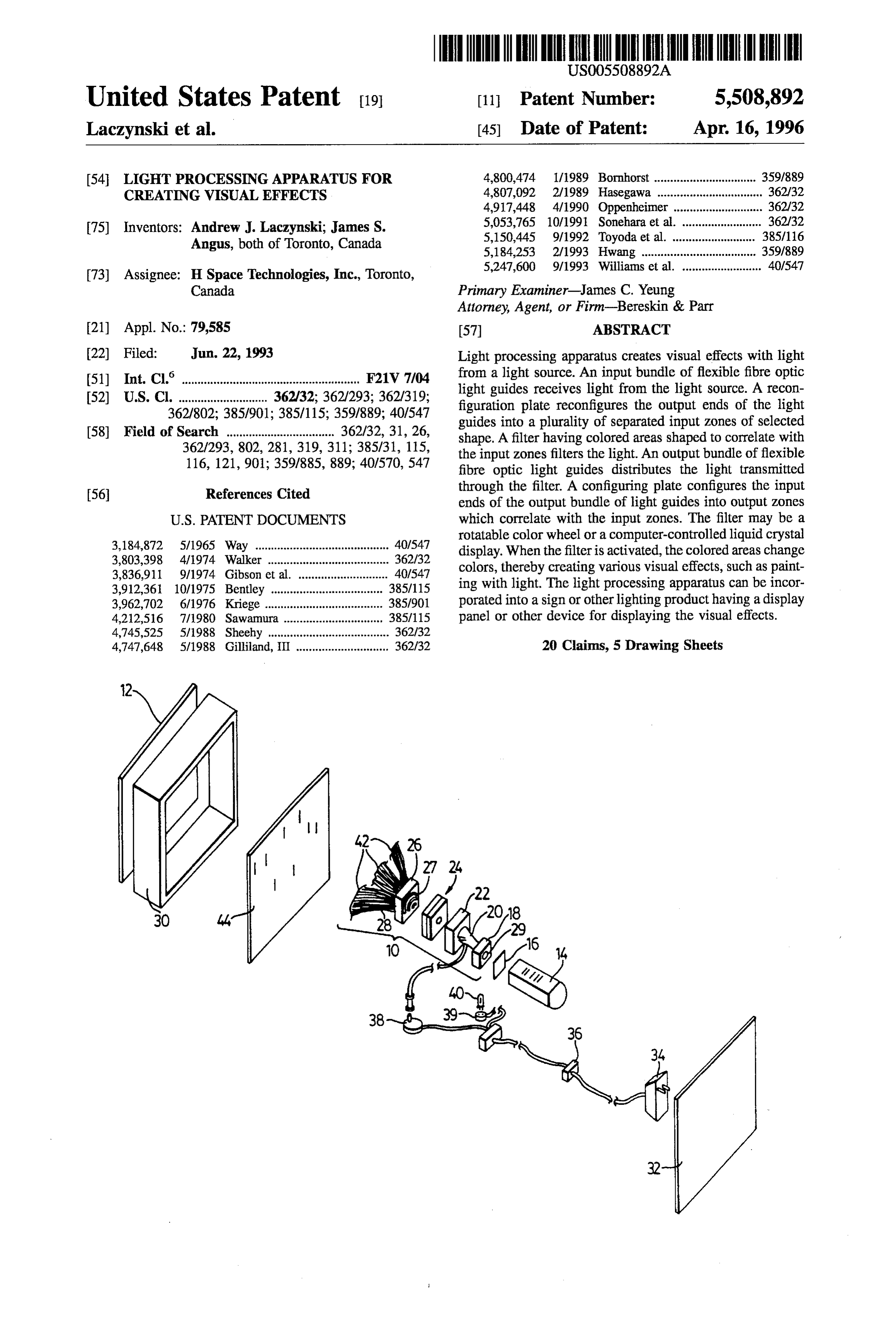
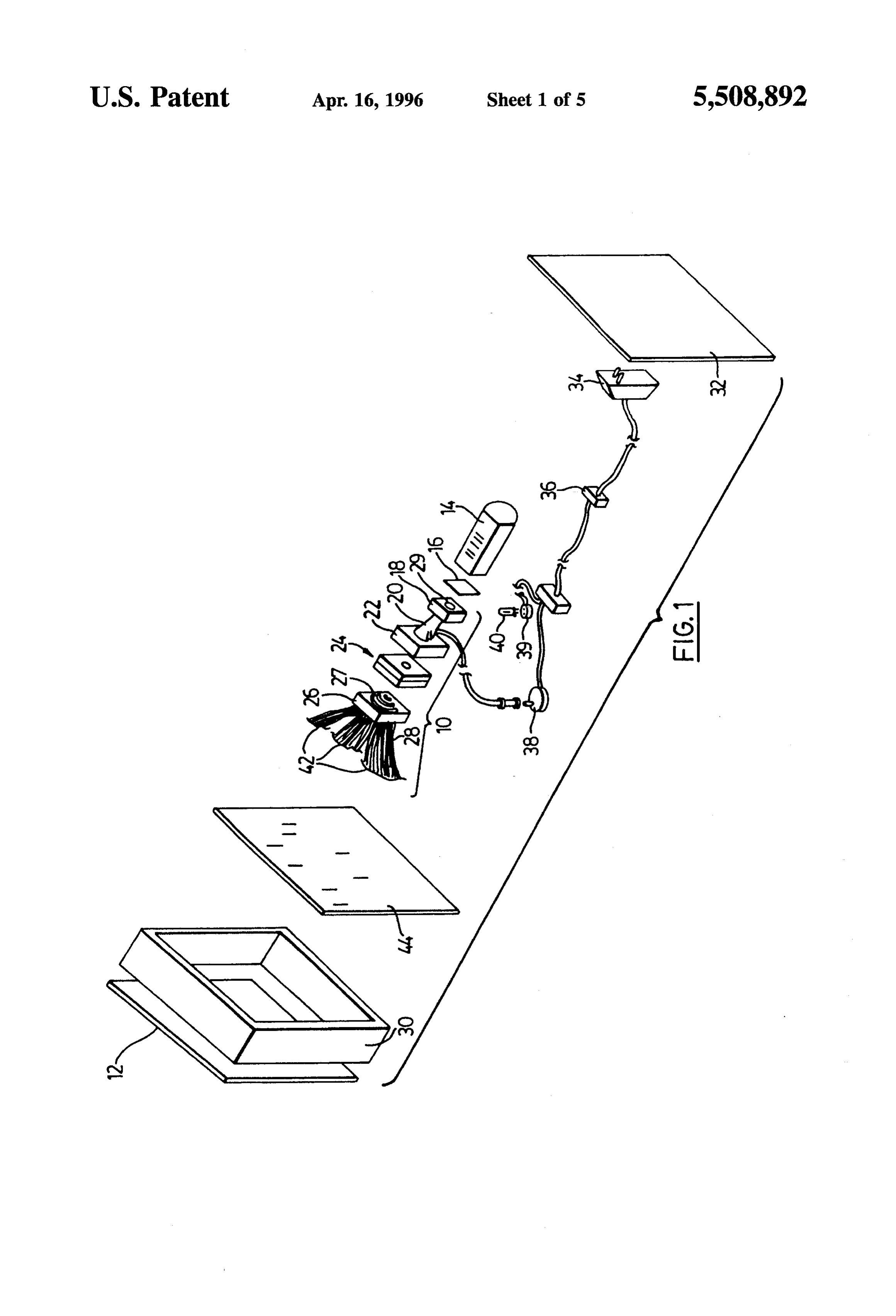
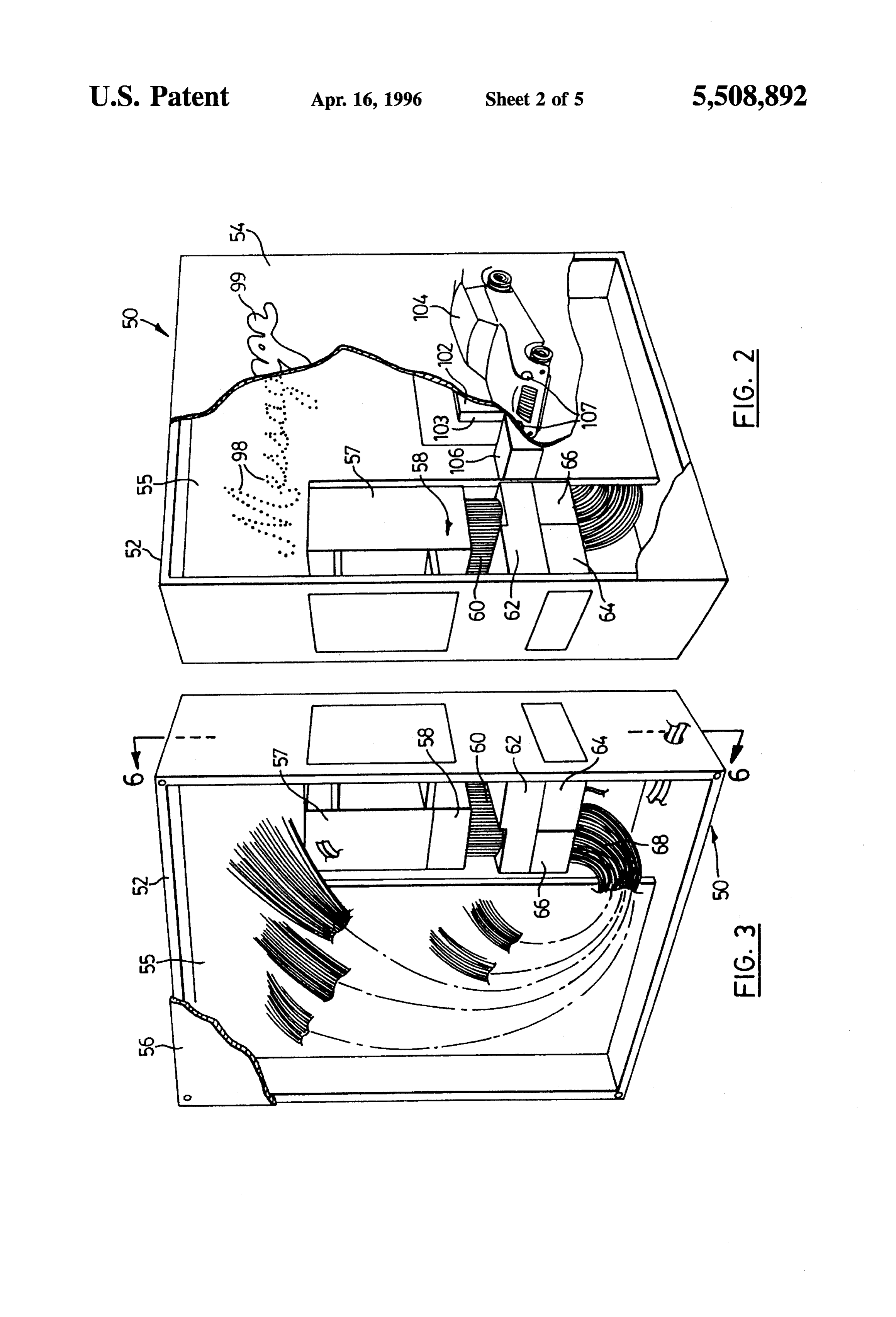
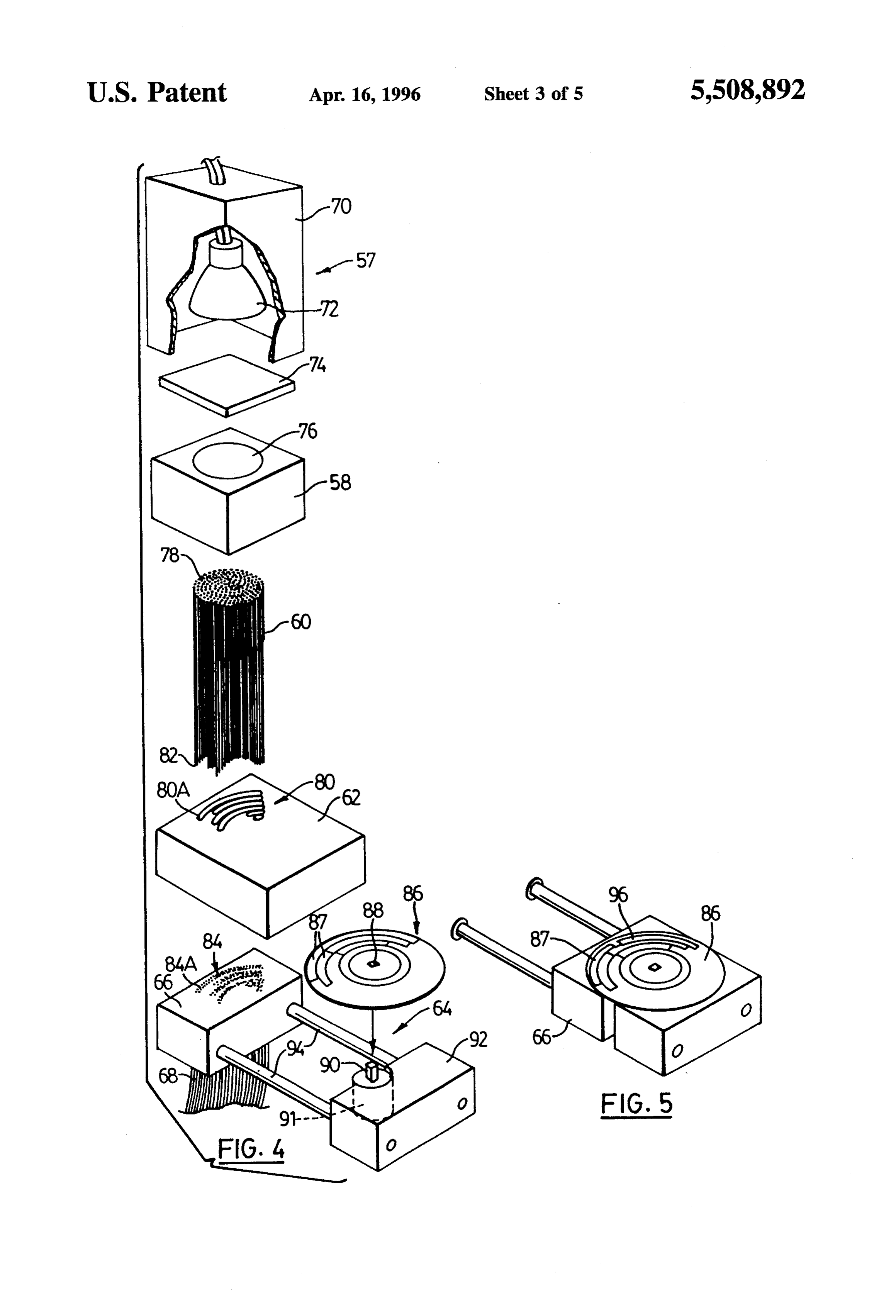
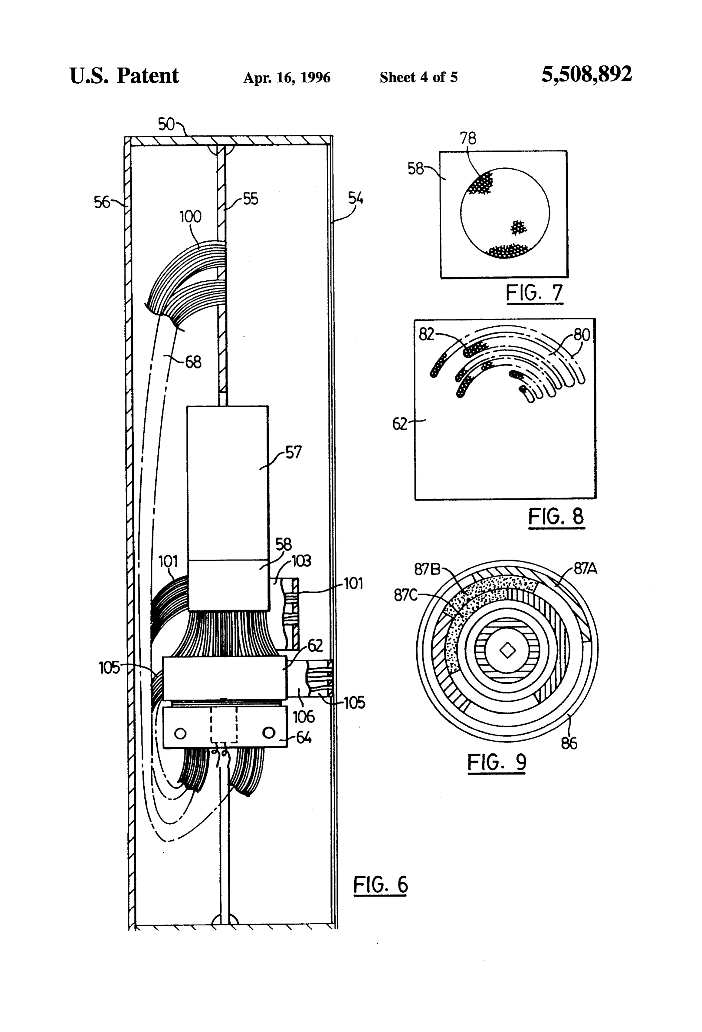
The present invention is directed to light processing accompanying drawings, in which: apparatus for creating visual effects with light from a light source. The subject light processing apparatus comprises FIG. 1 is an exploded diagrammatic view of the light input light distribution means for distributing light from the processing apparatus of the subject invention; light source into a plurality of inputlight paths, having input 50 FIG. 2 is a perspective view of a sign embodying a ends for receiving light from the light source and output preferred embodiment of the subject light processing appa ends, input light path reconfiguring means for reconfiguring ratus, with the front panel partially broken away; the output ends of the input distribution means into a FIG.3 is a perspective view of the back of the sign shown plurality of separated input zones of selected shape, filtering in FIG. 2, with the back panel mostly broken away; means for filtering the light emitted from the output ends of 55 FIG. 4 is an exploded perspective view of the components the input distribution means having filtering areas shaped to of the preferred embodiment of the subject light processing correlate with the input zones for transmitting light of apparatus;
pre-selected colours, filtered light distribution means for FIG. 5 is a perspective view of the colour wheel assembly distributing the light transmitted through the filtering means of the subject processing apparatus shown in its operating into a plurality of output light paths, having input ends and 60 position;
output ends, and filtered light configuring means for con figuring the input ends of the filtered light distribution means FIG. 6 is sectional view taken along lines 6-6 in FIG. 3; into output zones shaped to correlate with the input zones. and
In a preferred embodiment, the subject processing appa FIGS. 7, 8 and 9 are plan views of components of the ratus comprises light distribution means for distributing 65 preferred embodiment of the subject apparatus. flight from the light source into a multiplicity of light paths, FIG. 10 is an exploded perspective view of an alternative comprising an input bundle of flexible fibre optic light embodiment of the subject light management apparatus.
Page 8
BRIEF DESCRIPTION OF THE PREFERRED end plate 58, input bundle of light guides 60, input lightpath EMBODEMENTS reconfiguration plate 62, colour wheel assembly 64, output FIG. 1 illustrates in a diagrammatic fashion the main light path configuration light 66, and output bundle of light elements of the light processing or management apparatus of guides 68.
FIG. 4 is an exploded perspective view of the subject light the subject invention, shown generally as 10. Light process processing apparatus comprising common end plate 58, ing apparatus 10 is used to generate visual effects on a sign front or display panel 12, with light from a light source 14, input bundle of light guides 60, input light path reconfigu preferably focused into a circular pattern by lens 16. Pro ration plate 62, colour wheel assembly shown generally as cessing apparatus 10 comprises common end plate 18, input 64, output light path configuration plate 66, and output bundle or harness of fibre optic light guides 20, input light 10 bundle of light guides 68. Light source 57 includes light path reconfiguration plate 22, colour filter assembly 24, housing 70 having mounted therein light bulb 72 and lens output light path configuration plate 26, and output bundle 74.
or harness of fibre optic light guides 28. Common end plate 58 has circular aperture 76 for holding Common end plate 18 preferably has a large, central input ends 78 of input bundle of light guides 60. Inputlight circular aperture for holding the input ends of input bundle 15 path reconfiguration plate 62 has a series of arcuate slots 80 of light guides 20, so as to form common end 29 which for receiving the output ends 82 of input bundle of light receives light from light source 14. Alternatively, common guides 60. Output light path configuration plate 66 has a end plate aperture could be square or rectangular, depending series of arcuate slots 84, which are mirror-images of slots on the geometry of the light beam created by light source 14. 80, for receiving the input ends of output bundle of light Output light path configuration plate 26 has a series of slots 20 guides 68. The ends of the light guides are cut flush with the 27 for holding the input ends of output bundle of light guides surfaces of plates 62, 66 and highly polished to an optical 28. Input light path reconfiguration plate 22 has a similar standard.
series of slots, which are preferably mirror-images of slots Plates 62, 66 are preferably blocks of brass, polyethylene 27, for holding the output ends of input bundle of light or similar material, depending upon the nature of the fibre guides 20. As shown in FIG. 1, slots 27 are arcuate or 25 optics used for light guides 60, 68. Slots 80, 84 are prefer curved, so as to be used in conjunction with an active filter ably in the shape of a section of an annulus or ring. The assembly comprising a rotatable colour wheel having cir width and length of slots 80, 84 are selected depending upon cular geometry. Alternatively, filter assembly could be a the desired end effect to be created. Most end effects will computer-controlled active filter comprising liquid crystal require their own slot, although it is possible to create more screen having coloured areas, as discussed in more detail 30 than one separate visual effect with the same slot by appro hereinbelow, in which case slots 27 may not be curved. priate positioning of the tails of the light fibres held in such Processing apparatus 10 may be incorporated into a sign slot.
or other display means by mounting it within housing 30 Colour wheel assembly 64 comprises colour wheel 86 between display panel 12 and sign back 32. The sign 35 having a square central aperture 88 sized to fit square boss preferably includes transformer 34, terminal block36, AC or 90 on the drive shaft of motor 91 mounted on block 92. A DC motor 38 for activating colour filter assembly 24, and a pair of spaced rails 94 extend laterally from block 92 and are lamp socket 39 for holding light 40. Output or effect ends 42 slidably received in apertures in output light path configu of guides 28 are mounted onto intermediate support panel ration plate 66. In FIG. 4, block 92 is shown in its extended
40 position, allowing for colour wheel 86 to be conveniently
Input and output bundles of fibre optic light guides 20, 28 removed from drive shaft 90. In FIG. 5, block 92 is shown are preferably low-cost plastic (polymethyl methacrylate) in its operating position in which colour wheel 86 is shown fibres, although they may be glass (silica) fibres. The input in place covering arcuate slots 84 of plate 66. Alternatively, and output ends of both bundles of light guides 20, 28 are the colour wheel assembly could be fixed in place or highly polished or otherwise optically finished to an optical 45 mounted on a hinged block which would allow the colour quality standard so that maximum light transmission is wheel to be removed conveniently by swinging the front achieved. portion of the block outwardly.
Light emitted from light source 14 is focused by lens 16 Referring to FIG. 6 and FIG. 2, mounted within housing onto circular common end 29. Input bundle of light guides 50 is an intermediate support panel 55, for supporting the 20 distributes this light into a multiplicity of light paths 50 various components of the subject decorative lighting con separated into a plurality of input zones created by the output trol apparatus. Support panel 55 also holds the output ends ends of the light guides held in the series of slots in input or "tails” of the light fibres contained in output bundle of configuration plate 22. The light transmitted through these light guides 68. The tails of some light fibres 100 may be input zones is then filtered by colour filter assembly 24, and mounted directly in apertures 98 in support panel 55 to form is received by corresponding output Zones created by the 55 the letters of the "Message'99 shown in FIG. 2. Other light input ends of the output bundle of light guides 28 held in fibres 101 may be mounted in apertures 102 in block 103 slots 27 in output configuration plate 26. The light is then mounted onto the front surface of support panel 55 to bring distributed by the output ends or "tails' 42 of light guide the tails of fibres 101 closer to the translucent design such as bundle 28 to pre-selected locations on support panel 44, so the representation of an automobile 104 on the front surface as to illuminate selected translucent areas of display panel 60 54 of sign 50. Still other light fibres 105 are mounted on 12. Special effects simulating movement and flow are cre thicker block 106 secured to support panel 55 to create a ated when colour filter 24 is activated. brighter visual effect such as the headlight 107 of automobile FIGS. 2-9 illustrate a visual effects sign 50 embodying a 104.
preferred embodiment of the light processing apparatus of Referring now to FIGS. 7 and 8, shown therein are plan the subject invention. As shown in FIG. 2 and FIG. 3, sign 65 views of common end plate 58 and input light point recon 50 comprises housing 52, front effect panel 54, intermediate figuration plate 62, respectively. Input ends 78 of input support panel 55, back panel 56, light source 57, common bundle of light guides 60 are securely held in the central
Page 9
aperture of common end plate 58. The output ends 82 of bundle of light guides 120. Liquid crystal filter 114 may be input bundle of light guides 60 are reconfigured and a microprocessor-controlled active or passive liquid crystal mounted in curved or arcuate slots 80 of input light point matrix having a series of linear, elongated colour zones 122 configuration plate 62, as shown in FIG.7. Preferably, each which when activated by the microprocessor periodically arcuate slot 80 is wide enough to hold the output ends of two change colour. Output configuration plate 117 has a series of light fibres. The length of arcuate slots 80 depends upon the slots 124, which are preferably mirror images of slots 116, particular optical effect to be created. Alternatively, some or for holding input ends 126 of output light guides 128. all of the apertures in plates 62, 66 could take the form of Alternatively, while colour zones. 122 and slots 116 and 124 radially extending slots or circular apertures depending upon as illustrated define a plurality of linear, elongated light the desired end effect, 10 paths, it should be understood that colour zones 122 could assume other shapes (e.g. circular, amorphous), in which
As shown in FIG. 8, colour wheel 86 is preferably a case slots 116,124 would be reshaped to correspond there circular disc of acetate film, created either by printing from with. Light passing through slots 116 of input plate 110 is a computer program using a QMS system or the like, or by filtered by colour zones 122 as it passes therethrough. a film process such as Cibachrome or similar film transfer Preferably, when liquid crystal filter 112 is activated, colours process. Colour wheel 86 includes a plurality of coloured 15 flow across its surface in a pre-determined fashion to create zones 87A, 87B, 87C, etc. in the shape of annular sectors of the effect of painting with colour.
a circle, which correspond in width to arcuate slots 80, 84 to The processing apparatus of the subject invention makes prevent light cross-over from one zone to another. Coloured the input light more uniform, and provides more accurate Zones may be of one or more colours or transparent in whole 20 illumination of an end effects panel, particularly in the case or in part. The length of colour zones 87 depends upon the of animation. The reconfigured light paths created by the duration of the desired visual effect. In the case of each input harness annular sector 87, the portion of the annulus which is not reduce or eliminate of light guides and the reconfiguration plates coloured is opaque to prevent light from being transmitted another, while at the same light cross-over from one path to through such portion. time maximizing the amount of 25 light transmission through the colour wheel. The subject
In operation, light emitted from light 72 of light source 57 apparatus also reduces the risk of heat damage to the colour is focused by lens 74 onto common end 76 of common end wheel, because it is placed farther away from the light plate 58. First bundle of light guides 60 then distributes this source between the two configuration plates. As a result, light into a multiplicity of light paths separated into a light weight acetate colour wheels having a full range of plurality of light zones created by the output ends 82 of input 30 colour combinations, may be used and rotated with a small, bundle of light guides 60 held in arcuate slots 80. Light from low torque motor.
output ends 82 of input bundle 60 is then transmitted through colour wheel 86 and is received by input ends 84 of output as While the subject light processing apparatus is illustrated processing light used to produce visual effects on a bundle of light guides 68. As the input zones 80 are mirror display panel such as a sign, it should be appreciated that images of output zones 84, all of the light in a particular 35 such control apparatus can also be used in many other input Zone 80A is received by corresponding output zone lighting applications, such as moving light from one spot 84A. This light is then distributed by output bundle of light light to another in a pre-selected pattern, and holographic guides 68 to pre-selected locations behind display panel 54. and other displays.
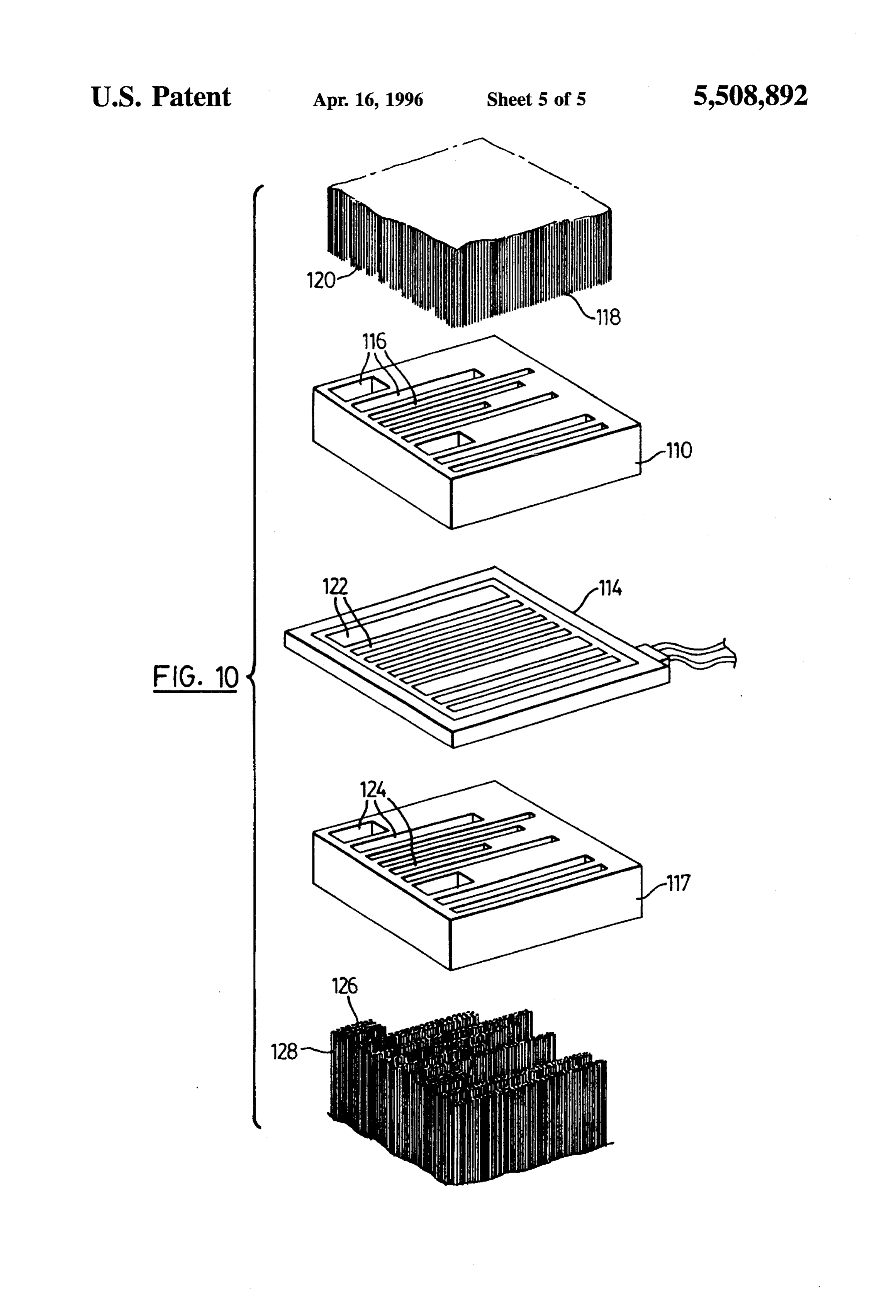
As colour wheel 86 is rotated by motor 91, various colour Further, while fibre optic light guides are the presently zones 87 periodically register with arcuate slots 80, 84, 40 preferred means for distributing light into a plurality of input resulting in the periodic transmission of filtered light. and output paths, other types of light, guides, such as As the leading edge of each coloured zone 87 crosses the water-filled tubes, could be used to so distribute the light. front end of fibre optically filled slots 80, 84, the coloured Likewise, a casting of light guiding material of appropriate light is transmitted through such fibres to display panel 54, creating the effect of movement and flow. Different designs 45 index for reflecting lightcoating shape having an exterior being with a suitable refractive transmitted therethrough, require different colour wheels and plates 60, 68 having an could be used instead of a plurality of light guides. appropriate number of slots of appropriate length. A "paint Thus while what is shown and described herein consti ing with light' effect can be created by proper sequencing of the output ends of the output bundle of light guides 68 on the tutes various preferred and alternative embodiments of the display panel, i.e. by placing the light fibres located in the 50 subject invention, it will be understood that various changes front of the arcuate slot at the beginning of the design, such can be made to such embodiments without departing from as the first letter of a word, and so on. the subject invention, the scope of which is defined in the Different end effects can be created by varying the length appended claims.
We claim:
of arcuate slots 80, 84 and the length of colour wheel zones 87. For example, a short burst of colour running through an 55 with1. light
Light processing apparatus for creating visual effects from a light source, comprising:
effect would be produced by a short colour wheel Zone and a) inputlight distribution means for distributing light from a correspondingly long slot on configuration plates 60, 68.
Conversely, an area on the display panel which continuously the light source into a plurality of input light paths, changes colour would require a colour path or zone around having input ends for receiving light from the light the full circumference of the colour wheel 86 and a short slot 60 source and output ends;
on plates 60, 68. b) input light path reconfiguring means for reconfiguring Referring now to FIG. 10, in an alternative embodiment, the output ends of the input distribution means into a the subject light processing means comprises a square input plurality of separated input Zones of selected shape; reconfiguration plate 110, liquid crystal filter 114, and square c) filtering means for filtering the light emitted from the output configuration plate 117. Reconfiguration plate 110 65 output ends of the input distribution means, having has a series of aligned straight, elongated slots 116 of filtering areas shaped to correlate with the input zones pre-selected lengths for holding the output ends 118 of input for transmitting light of pre-selected colours;
Page 10
d) filtered light distribution means for distributing the c) filtering means for filtering the light emitted from the light transmitted through the filtering means into a output ends of the input bundle of light guides, having plurality of output light paths, having input ends and filtering areas shaped to correlate with the input Zones, output ends; and adapted to transmit light of pre-selected colours; e) filtered light configuring means for configuring the 5 d) filtered light distribution means for distributing the input ends of the filtered light distribution means into light transmitted through the filter means, comprising output zones shaped to correlate with the input zones. an output bundle of flexible fibre optic light guides 2. Apparatus defined in claim 1, wherein the input light having optically finished input ends and output ends; distribution means comprises an input bundle of flexible and light guides having input ends for receiving the light from O e) filtered light configuring means for configuring the the light source, and output ends. input ends of the output bundle of light guides into 3. Apparatus as defined in claim 2, wherein the filtered output zones shaped to correlate with the input Zones. light distribution means comprises an output bundle of 15. The apparatus defined in claim 14, wherein the input flexible light guides having input ends and output ends. light path reconfiguring means comprises a plate having a 4. The apparatus defined in claim 3, wherein the input 15 series of slots therein each dimensioned to securely hold the Zones and output Zones comprise arcuate paths. output ends of a portion of the input bundle of light guides. 5. The apparatus defined in claim 3, wherein the output 16. The apparatus defined in claim 15, wherein the input light path configuration means comprises a plate having a light distribution means also comprises a common end plate series of arcuate slots therein dimensioned to securely hold having an aperture for securely holding the input ends of the the input ends of the output bundle of light guides. 20 input bundle of light guides.
6. The apparatus defined in claim 2, wherein the input 17. The apparatus defined in claim 16, wherein the output light path reconfiguring means comprises a plate having a light path configuration means comprises a plate having a series of arcuate slots therein each dimensioned to securely series of slots therein dimensioned to securely hold the input hold the output ends of a portion of the input bundle of light ends of the output bundle of light guides. guides. 25 18. The apparatus defined in claim 17, wherein the slots 7. The apparatus defined in claim 6, wherein the input are arcuate shaped.
light distribution means also comprises a common end plate 19. The apparatus as defined in claim 17, wherein the slots having an aperture for securely holding the input ends of the are linear.
input bundle of light guides. 20. A visual effects sign, comprising: 8. The apparatus defined in claim 4, wherein the input and 30 a) a housing;
output zones are mirror images. b) a light source mounted in the housing; 9. The apparatus defined in claim 1, wherein the filtering c) input light distribution means mounted adjacent the means comprises an active filter having filtering areas which light source for distributing light from the light source change colour when the filter is activated. into a multiplicity of input light paths, having input 10. The apparatus defined in claim 9, wherein the active 35 ends for receiving light from the light source and output filter comprises a rotatable circular colour wheel having ends;
coloured Zones in the shape of annular sectors of a circle. d) input light path reconfiguring means for reconfiguring 11. The apparatus defined in claim 9, wherein the active filter comprises a computer-controlled panel having the output ends of the input distribution means into a coloured zones of pre-selected shapes. 40 plurality of separated input Zones of selected shape; 12. The apparatus defined in claim 11, wherein the panel e) filtering means for filtering the light emitted from the is a liquid crystal display. output end of the input distribution means, having 13. The apparatus defined in claim 1, further comprising filtering areas shaped to correlate with the input Zones, display means for receiving the output ends of the filtered adapted to transmit light of pre-selected colours; light distribution means in a pre-selected manner so as to 45 f) filtered light distribution means for distributing the light create pre-determined visual effects. transmitted through the filter means into a multiplicity 14. Light processing apparatus for creating visual effects of output light paths, having input ends and output with light from a light source, comprising: ends;
a) light distribution means for distributing light from the 50 g) filtered light configuring means for configuring the light source into a multiplicity of light paths, compris input ends of the filtered light distribution means into ing an input bundle of flexible fibre optic light guides output Zones shaped to correlate with the input Zones; having optically finished input ends for receiving the and light from the light source, and optically finished output h) display means for receiving the output ends of the ends; filtered light distribution means in a pre-selected pat
b) input light path reconfiguring means for configuring the ten.
output ends of the input light guides into a plurality of separated input Zones of selected shape;
Provenance
- Collection
- Cited prior art
- Original PDF
- patentimages.storage.googleapis.com →
- Filed
- 1993-06-22
- Pages
- 10
- Method
- pdftotext (the PDF's own text layer) + pdftoppm 300dpi page scans
- Source
- Google Patents bibliographic record
- Granted
- 1996-04-16
- Inventors
- Andrew J. Laczynski; James S. Angus; H Space Technologies Inc
- Transcribed from
- patentimages.storage.googleapis.com →