patent · US4483585
Illuminating device having optical light guide formed as fibre bundle
20 November 1984
Page 1 — bibliographic record
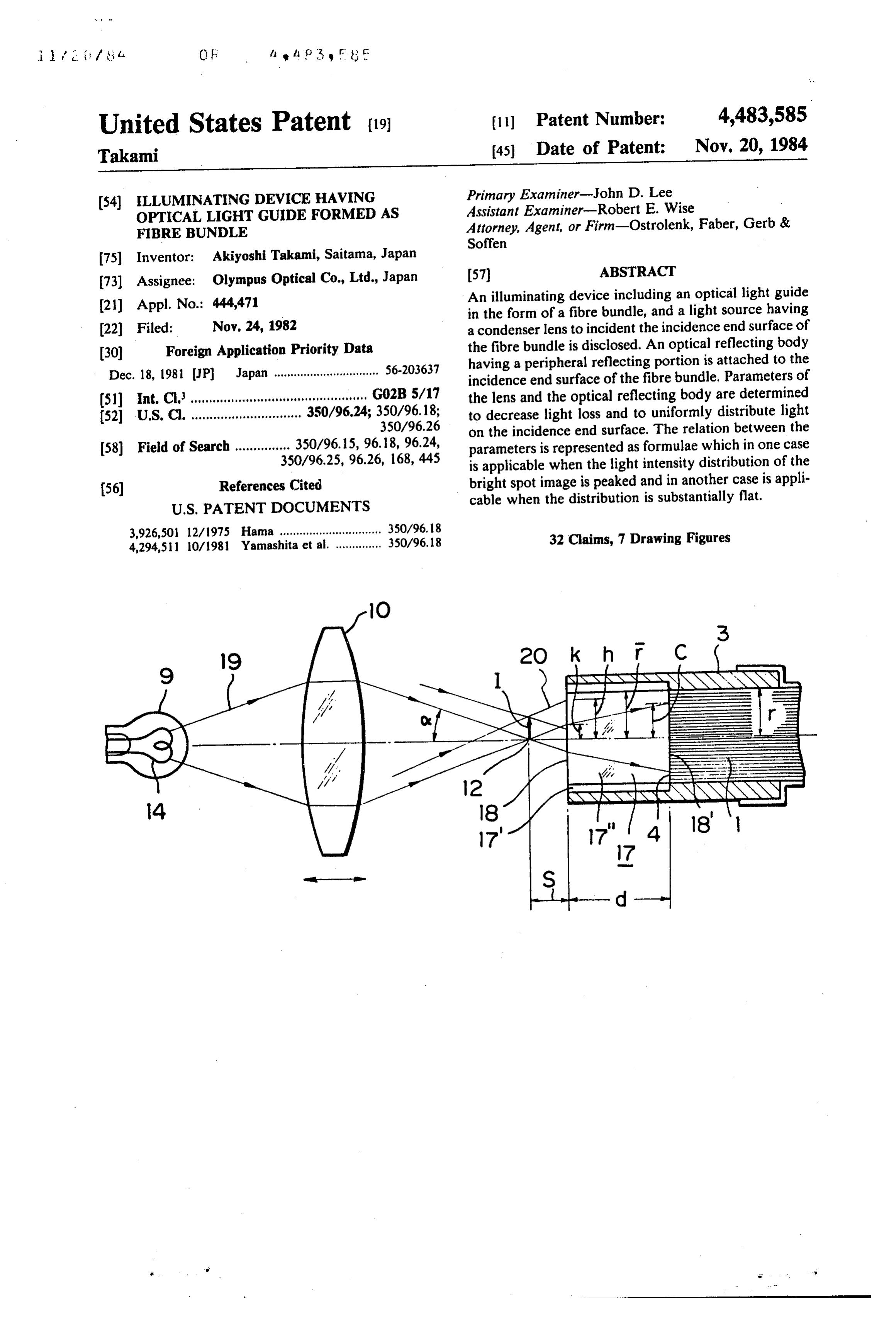
United States Patent (19) 11 Patent Number: 4,483,585 Takami 45 Date of Patent: Nov. 20, 1984
(54) ILLUMINATING DEVICE HAVING Primary Examiner-John D. Lee OPTICAL LIGHT GUIDE FORMED AS Assistant Examiner-Robert E. Wise
FIBRE BUNDLE Attorney, Agent, or Firm-Ostrolenk, Faber, Gerb & Soffen 75) Inventor: Akiyoshi Takami, Saitama, Japan 73) Assignee: Olympus Optical Co., Ltd., Japan 57 ABSTRACT (21) Appl. No.: 444,471 An illuminating device including an optical light guide in the form of a fibre bundle, and a light source having (22 Filed: Nov. 24, 1982 a condenser lens to incident the incidence end surface of (30) Foreign Application Priority Data the fibre bundle is disclosed. An optical reflecting body having a peripheral reflecting portion is attached to the
Dec. 18, 1981 JP Japan ................................ 56-203637 incidence end surface of the fibre bundle. Parameters of (51) Int. Cli............................................... G02B5/17 the lens and the optical reflecting body are determined 52 U.S. C. .............................. 350/96.24; 350/96.18; to decrease light loss and to uniformly distribute light 350/96.26 on the incidence end surface. The relation between the 58) Field of Search ............... 350/96.15, 96.18, 96.24, parameters is represented as formulae which in one case 350/96.25, 96.26, 168, 445 is applicable when the light intensity distribution of the (56) References Cited bright spot image is peaked and in another case is appli
3,926,501 12/1975 Hama ............................... 350/96.18 32 Claims, 7 Drawing Figures
Sai SSNL
EAEE
NSNRN
Page 2
Drawing sheet — no readable text.
Page 3
Drawing sheet — no readable text.
Page 4
Drawing sheet — no readable text.
Page 5
Drawing sheet — no readable text.
Page 6
attached to the incidence end surface of the fibre bun
ILLUMINATING DEVICE HAVING OPTICAL dle. Parameters, i.e. radius, length and refractive index LIGHT GUIDE FORMED AS FIBRE BUNDLE of the optical reflecting body, effective radius of the fibre bundle, air equivalent length between the bright
BACKGROUND OF THE INVENTION 5 spot image of illuminating light and incidence end sur face
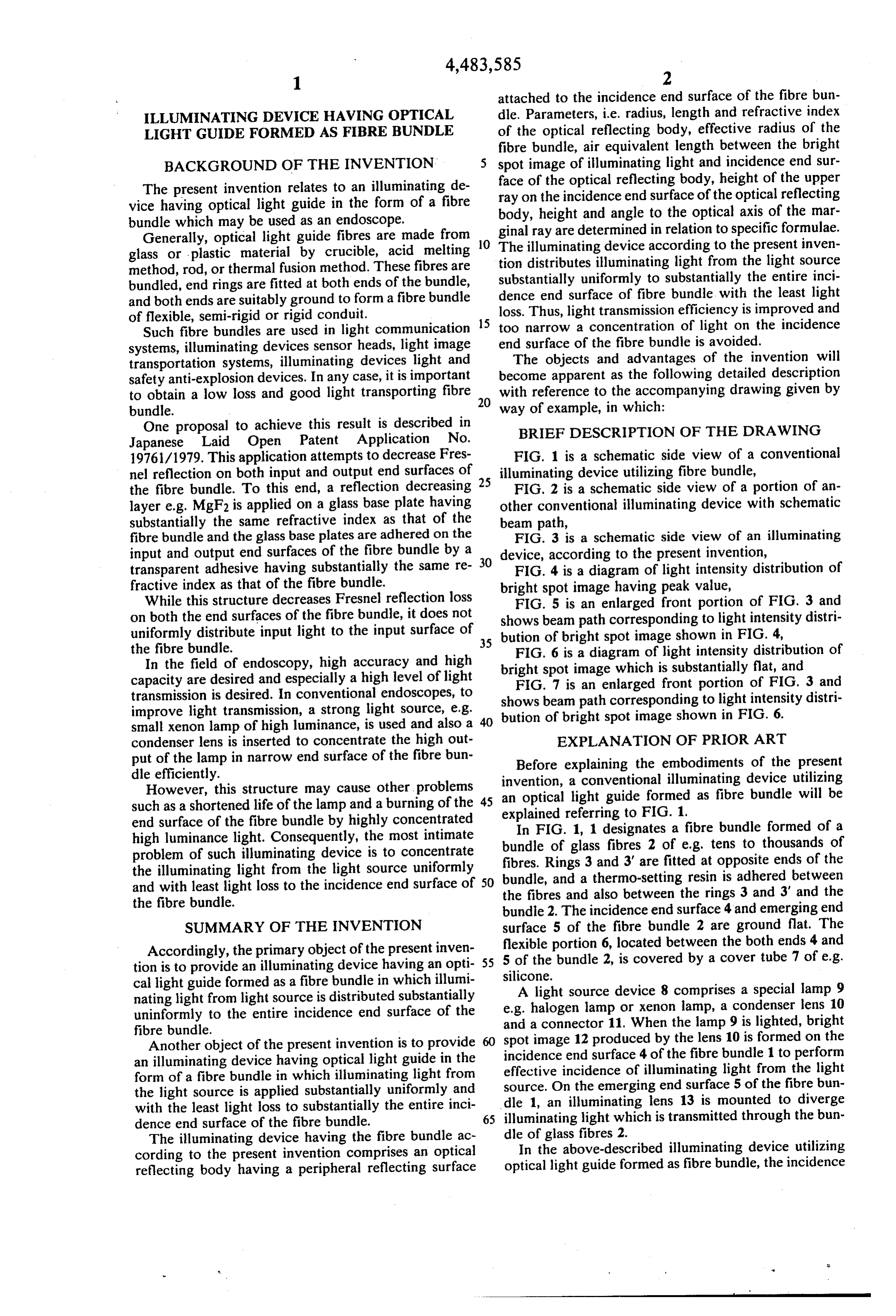
The present invention relates to an illuminating de ray on the of the optical reflecting body, height of the upper vice having optical light guide in the form of a fibre body, height incidence end surface of the optical reflecting bundle which may be used as an endoscope. and angle to the optical axis of the mar Generally, optical light guide fibres are made from 10 The ginal ray are determined in relation to specific formulae. glass or plastic material by crucible, acid melting tion illuminating device according to the present inven distributes illuminating light from the light source method, rod, or thermal fusion method. These fibres are substantially uniformly to substantially the entire inci bundled, end rings are fitted at both ends of the bundle, and both ends are suitably ground to form a fibre bundle dence end surface of fibre bundle with the least light of flexible, semi-rigid or rigid conduit. loss. Thus, light transmission efficiency is improved and Such fibre bundles are used in light communication 15 too narrow a concentration of light on the incidence systems, illuminating devices sensor heads, light image end surface of the fibre bundle is avoided. transportation systems, illuminating devices light and The objects and advantages of the invention will safety anti-explosion devices. In any case, it is important become apparent as the following detailed description to obtain a low loss and good light transporting fibre 20 with reference to the accompanying drawing given by bundle. way of example, in which:
One proposal to achieve this result is described in BRIEF DESCRIPTION OF THE DRAWING Japanese Laid Open Patent Application No.
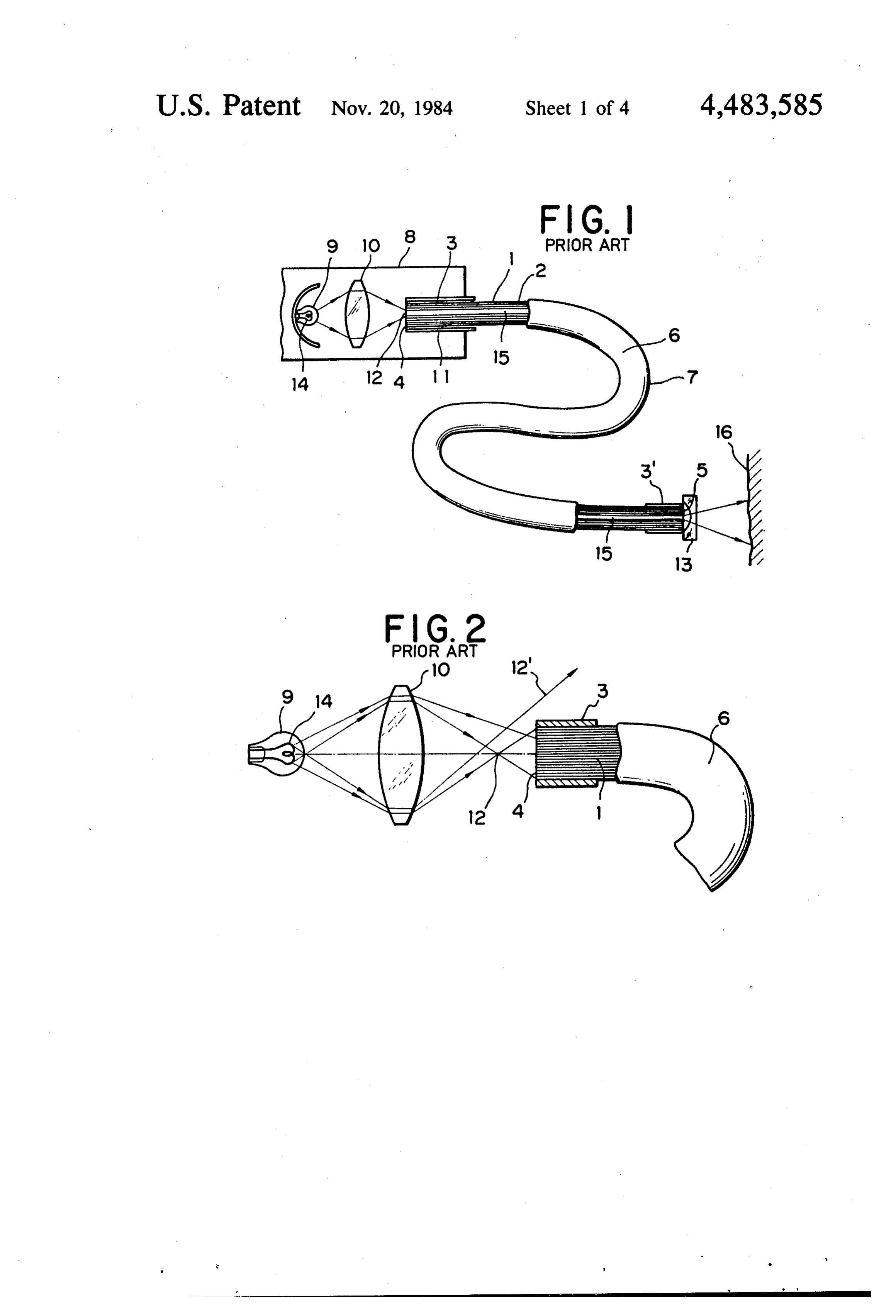
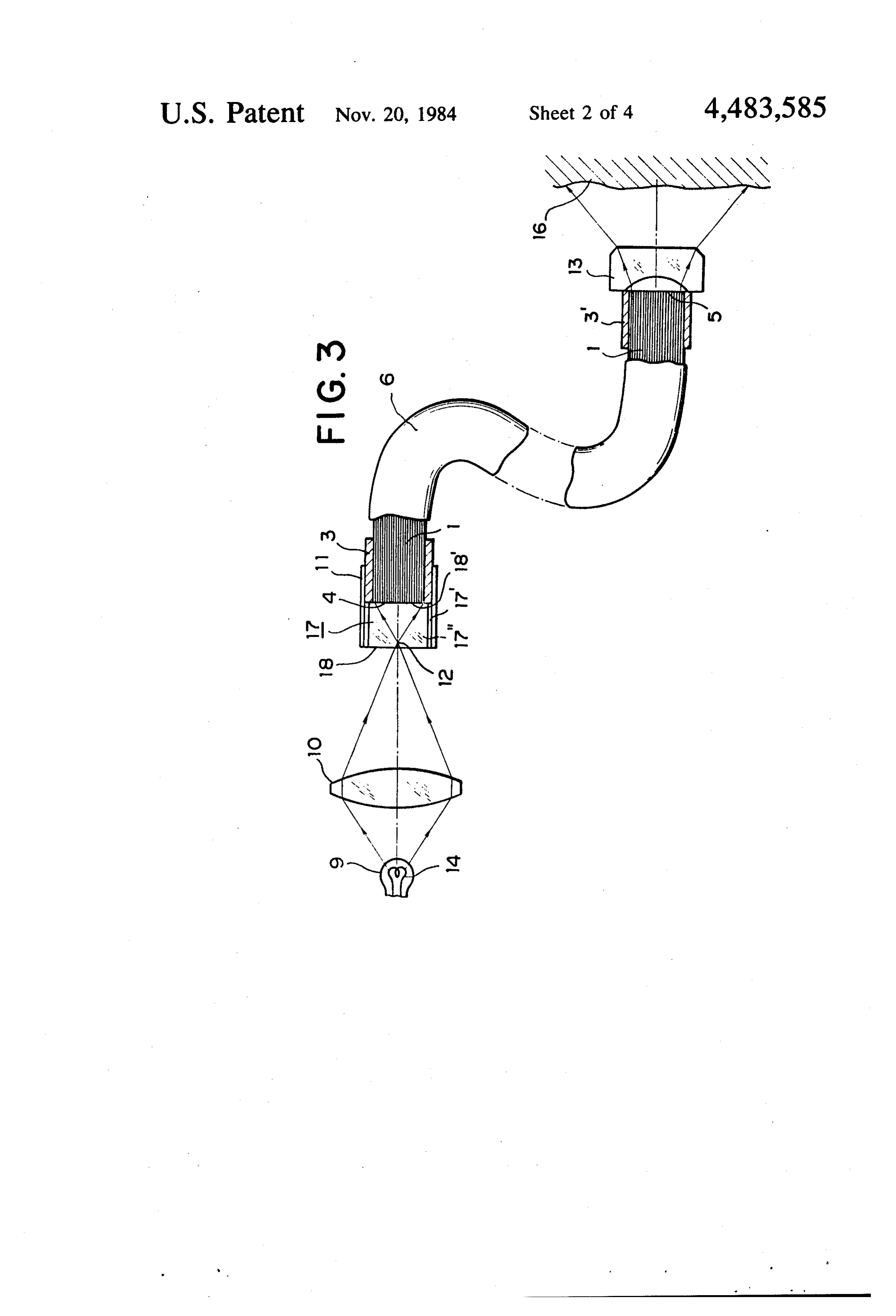
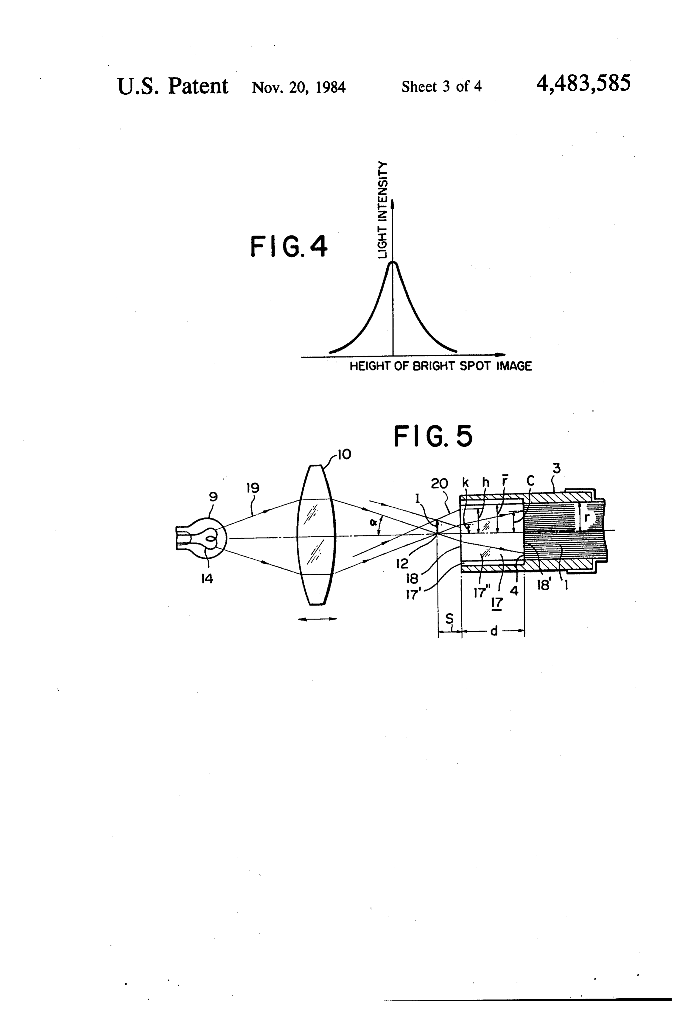
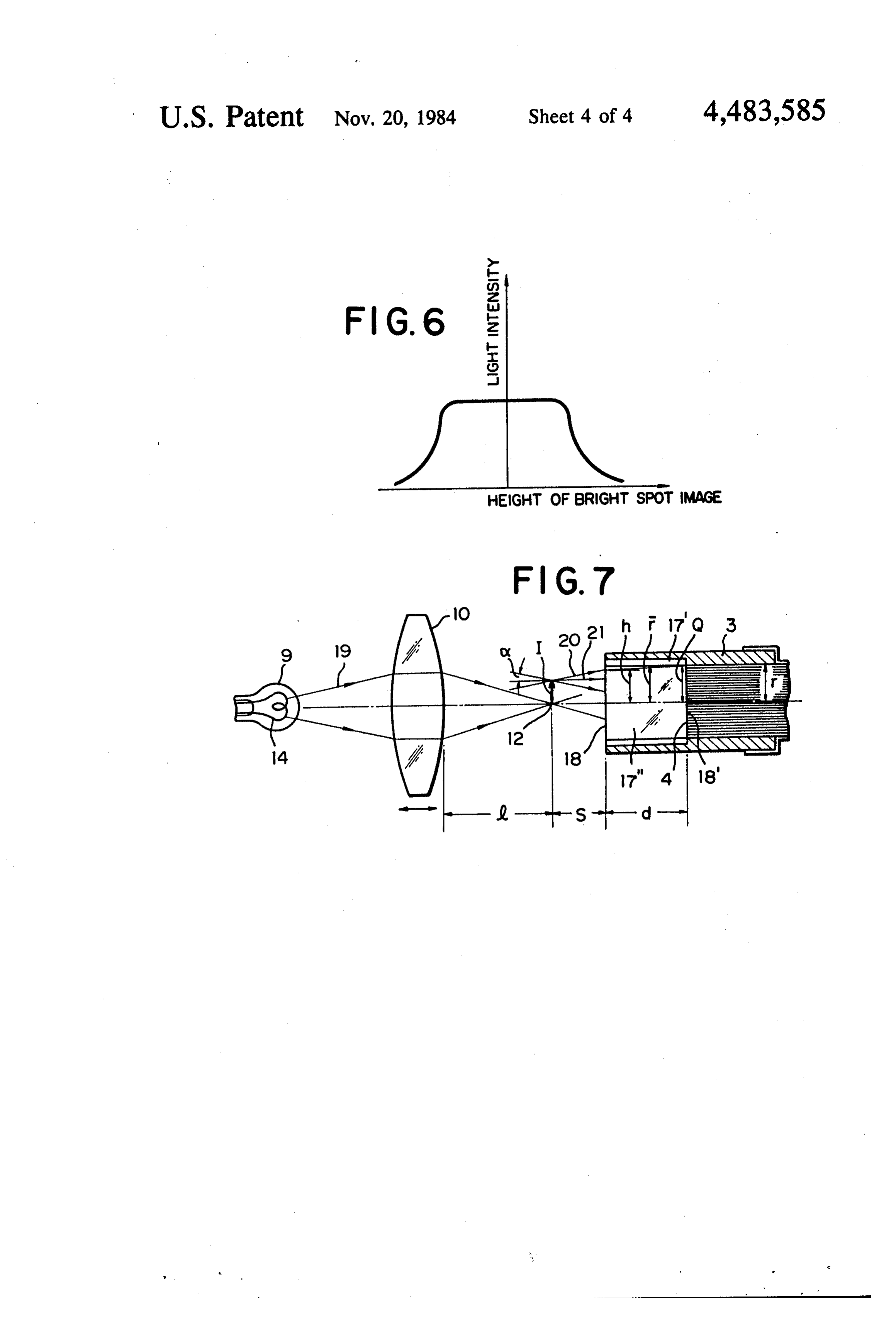
19761/1979. This application attempts to decrease Fres FIG. 1 is a schematic side view of a conventional nel reflection on both input and output end surfaces of 25 illuminating device utilizing fibre bundle, the fibre bundle. To this end, a reflection decreasing FIG. 2 is a schematic side view of a portion of an layer e.g. MgF2 is applied on a glass base plate having other conventional illuminating device with schematic substantially the same refractive index as that of the beam path, fibre bundle and the glass base plates are adhered on the FIG. 3 is a schematic side view of an illuminating input and output end surfaces of the fibre bundle by a 30 device, according to the present invention, transparent adhesive having substantially the same re FIG. 4 is a diagram of light intensity distribution of fractive index as that of the fibre bundle. bright spot image having peak value, While this structure decreases Fresnel reflection loss FIG. 5 is an enlarged front portion of FIG. 3 and on both the end surfaces of the fibre bundle, it does not shows beam path corresponding to light intensity distri uniformly distribute input light to the input surface of 35 bution of bright spot image shown in FIG. 4, the fibre bundle. FIG. 6 is a diagram of light intensity distribution of In the field of endoscopy, high accuracy and high bright spot image which is substantially flat, and capacity are desired and especially a high level of light FIG. 7 is an enlarged front portion of FIG. 3 and transmission is desired. In conventional endoscopes, to shows beam path corresponding to light intensity distri improve light transmission, a strong light source, e.g.
small xenon lamp of high luminance, is used and also a 40 bution of bright spot image shown in FIG. 6. condenser lens is inserted to concentrate the high out EXPLANATION OF PRIOR ART put of the lamp in narrow end surface of the fibre bun Before explaining the embodiments of the present dle efficiently.
However, this structure may cause other problems an optical alight invention, conventional illuminating device utilizing guide formed as fibre bundle will be
such as a shortened life of the lamp and a burning of the explained referring end surface of the fibre bundle by highly concentrated to FIG. 1. high luminance light. Consequently, the most intimate bundle of glass fibres 2 ofa e.g.
In FIG. 1, 1 designates fibre bundle formed of a problem of such illuminating device is to concentrate fibres. Rings 3 and 3' are fitted attens to thousands of opposite ends of the the illuminating light from the light source uniformly bundle, and a thermo-setting resin is adhered and with least light loss to the incidence end surface of 50 the fibres and also between the rings 3 and 3'between and the the fibre bundle. bundle 2. The incidence end surface 4 and emerging end SUMMARY OF THE INVENTION surface 5 of the fibre bundle 2 are ground flat. The Accordingly, the primary object of the present inven 5flexible portion 6, located between the both ends 4 and tion is to provide an illuminating device having an opti silicone. bundle 2, is covered by a cover tube 7 of e.g.
cal light guide formed as a fibre bundle in which illumi nating light from light source is distributed substantially e.g.A halogen light source device 8 comprises a special lamp 9 lamp or xenon lamp, a condenser lens 10 uninformly to the entire incidence end surface of the and a connector 11. When the lamp 9 is lighted, bright fibre bundle.
Another object of the present invention is to provide spot image 12 produced by the lens 10 is formed on the an illuminating device having optical light guide in the incidence end surface 4 of the fibre bundle 1 to perform form of a fibre bundle in which illuminating light from effective incidence of illuminating light from the light the light source is applied substantially uniformly and source. On the emerging end surface 5 of the fibre bun with the least light loss to substantially the entire inci idle 1, an illuminating lens 13 is mounted to diverge dence end surface of the fibre bundle. 65 illuminating light which is transmitted through the bun The illuminating device having the fibre bundle ac dleInofthe glass fibres 2.
above-described illuminating device utilizing cording to the present invention comprises an optical reflecting body having a peripheral reflecting surface optical light guide formed as fibre bundle, the incidence
Page 7
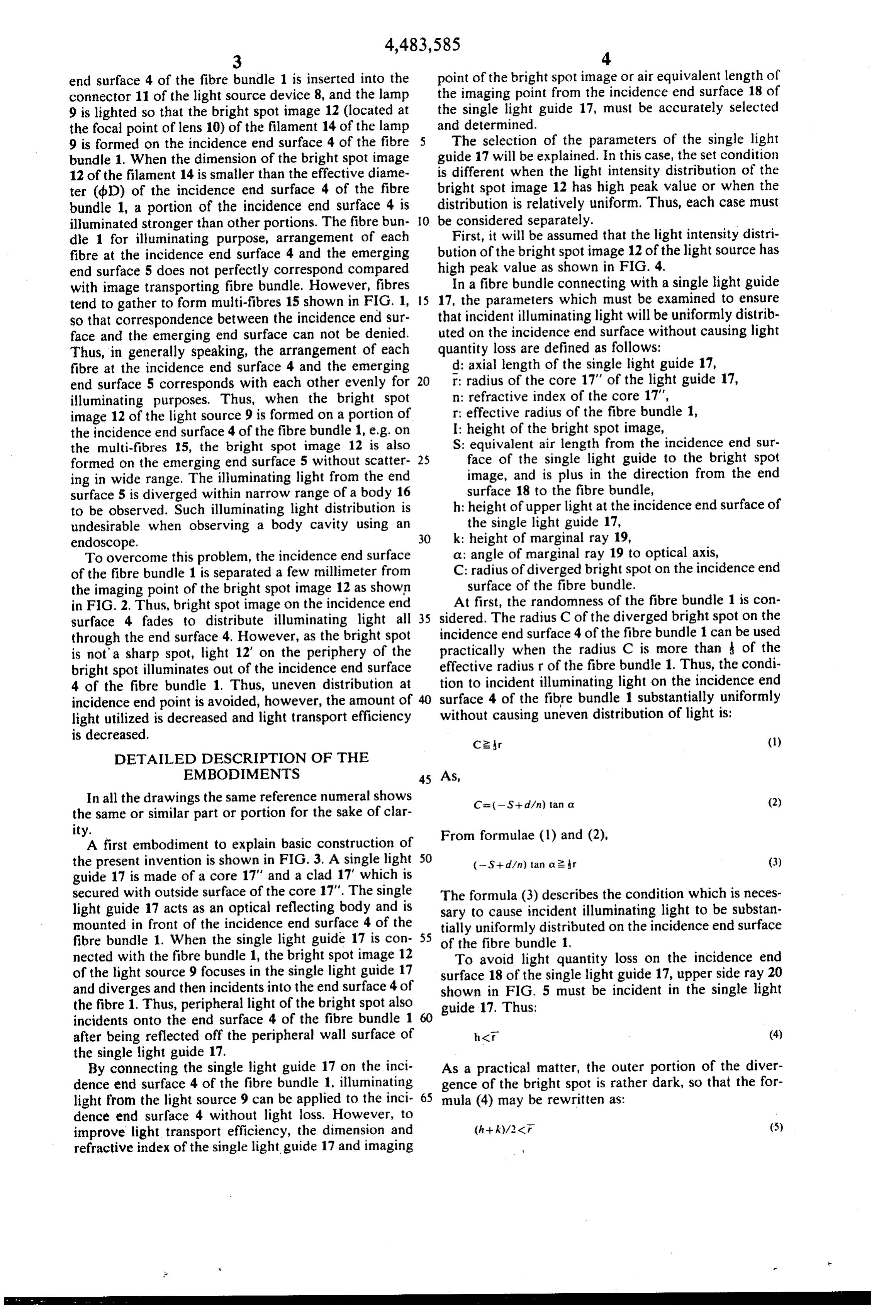
end surface 4 of the fibre bundle 1 is inserted into the point of the bright spot image or air equivalent length of connector 11 of the light source device 8, and the lamp the imaging point from the incidence end surface 18 of 9 is lighted so that the bright spot image 12 (located at the single light guide 17, must be accurately selected the focal point of lens 10) of the filament 14 of the lamp and determined.
9 is formed on the incidence end surface 4 of the fibre The selection of the parameters of the single light bundle 1. When the dimension of the bright spot image guide 17 will be explained. In this case, the set condition 12 of the filament 14 is smaller than the effective diame is different when the light intensity distribution of the ter (dbD) of the incidence end surface 4 of the fibre bright spot image 12 has high peak value or when the bundle 1, a portion of the incidence end surface 4 is distribution is relatively uniform. Thus, each case must illuminated stronger than other portions. The fibre bun O be considered separately.
dle 1 for illuminating purpose, arrangement of each First, it will be assumed that the light intensity distri fibre at the incidence end surface 4 and the emerging bution of the bright spot image 12 of the light source has end surface 5 does not perfectly correspond compared high peak value as shown in FIG. 4.
with image transporting fibre bundle. However, fibres In a fibre bundle connecting with a single light guide tend to gather to form multi-fibres 15 shown in FIG. 1, 15 17, the parameters which must be examined to ensure so that correspondence between the incidence end sur that incident illuminating light will be uniformly distrib face and the emerging end surface can not be denied. uted on the incidence end surface without causing light Thus, in generally speaking, the arrangement of each quantity loss are defined as follows:
fibre at the incidence end surface 4 and the emerging d: axial length of the single light guide 17, end surface 5 corresponds with each other evenly for 20 r: radius of the core 17" of the light guide 17, illuminating purposes. Thus, when the bright spot n: refractive index of the core 17', image 12 of the light source 9 is formed on a portion of r: effective radius of the fibre bundle 1, the incidence end surface 4 of the fibre bundle 1, e.g. on I: height of the bright spot image, the multi-fibres 15, the bright spot image 12 is also S: equivalent air length from the incidence end sur formed on the emerging end surface 5 without scatter 25 face of the single light guide to the bright spot ing in wide range. The illuminating light from the end image, and is plus in the direction from the end surface 5 is diverged within narrow range of a body 16 surface 18 to the fibre bundle, to be observed. Such illuminating light distribution is h: height of upper light at the incidence end surface of undesirable when observing a body cavity using an the single light guide 17, endoscope. 30 k: height of marginal ray 19, To overcome this problem, the incidence end surface a: angle of marginal ray 19 to optical axis, of the fibre bundle 1 is separated a few millimeter from C: radius of diverged bright spot on the incidence end the imaging point of the bright spot image 12 as shown surface of the fibre bundle. in FIG. 2. Thus, bright spot image on the incidence end At first, the randomness of the fibre bundle 1 is con surface 4 fades to distribute illuminating light all 35 sidered. The radius C of the diverged bright spot on the through the end surface 4. However, as the bright spot incidence end surface 4 of the fibre bundle 1 can be used is not a sharp spot, light 12" on the periphery of the practically when the radius C is more than of the bright spot illuminates out of the incidence end surface effective radius r of the fibre bundle 1. Thus, the condi 4 of the fibre bundle 1. Thus, uneven distribution at tion to incident illuminating light on the incidence end incidence end point is avoided, however, the amount of 40 surface 4 of the fibre bundle 1 substantially uniformly light utilized is decreased and light transport efficiency without causing uneven distribution of light is: is decreased.
DETALED DESCRIPTION OF THE
In all the drawings the same reference numeral shows C = (-S+ dan) tan a (2) the same or similar part or portion for the sake of clar ity.
A first embodiment to explain basic construction of From formulae (l) and (2), the present invention is shown in FIG. 3. A single light 50 (-S--d/n) tan a 2 r (3) guide 17 is made of a core 17" and a clad 17" which is secured with outside surface of the core 17". The single The formula (3) describes the condition which is neces light guide 17 acts as an optical reflecting body and is sary to cause incident illuminating light to be substan mounted in front of the incidence end surface 4 of the tially uniformly distributed on the incidence end surface fibre bundle 1. When the single light guide 17 is con 55 of the fibre bundle 1, nected with the fibre bundle 1, the bright spot image 12 To avoid light quantity loss on the incidence end of the light source 9 focuses in the single light guide 17 surface 18 of the single light guide 17, upper side ray 20 and diverges and then incidents into the end surface 4 of shown in FIG. 5 must be incident in the single light the fibre 1. Thus, peripheral light of the bright spot also guide 17. Thus:
incidents onto the end surface 4 of the fibre bundle 1 60 after being reflected off the peripheral wall surface of h (f (4) the single light guide 17.
By connecting the single light guide 17 on the inci As a practical matter, the outer portion of the diver dence end surface 4 of the fibre bundle 1, illuminating gence of the bright spot is rather dark, so that the for light from the light source 9 can be applied to the inci 65 mula (4) may be rewritten as:
dence end surface 4 without light loss. However, to improve light transport efficiency, the dimension and refractive index of the single light guide 17 and imaging
Page 8
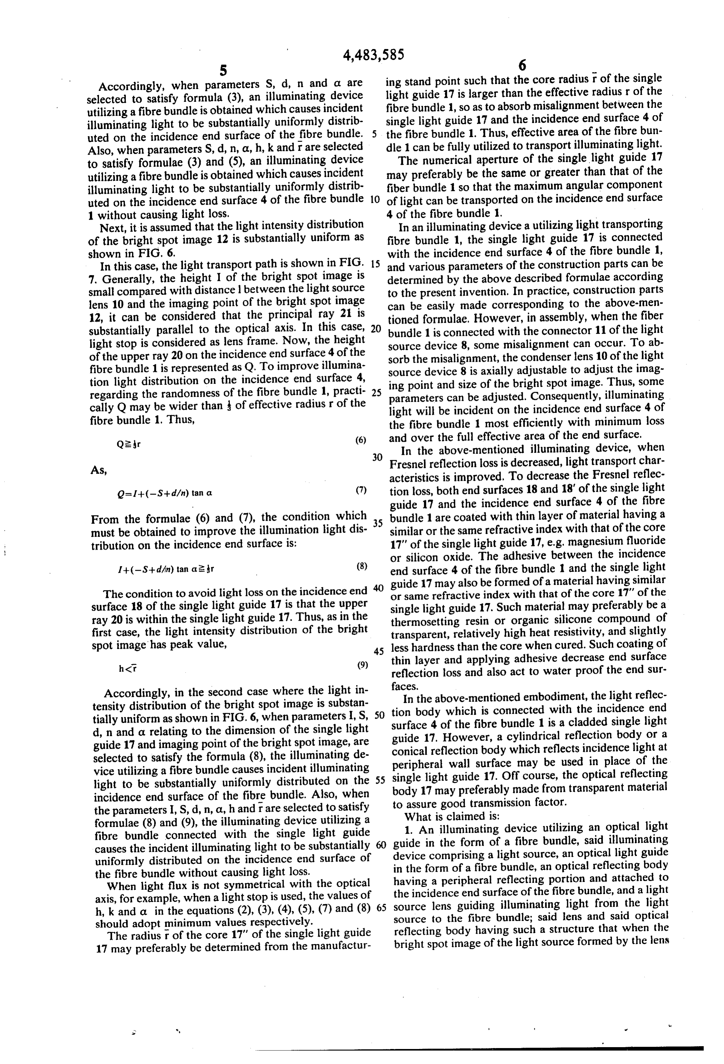
Accordingly, when parameters S, d, n and a are ing stand point such that the core radius r of the single selected to satisfy formula (3), an illuminating device light guide 17 is larger than the effective radius r of the utilizing a fibre bundle is obtained which causes incident fibre bundle 1, so as to absorb misalignment between the illuminating light to be substantially uniformly distrib single light guide 17 and the incidence end surface 4 of uted on the incidence end surface of the fibre bundle. the fibre bundle 1. Thus, effective area of the fibre bun Also, when parameters S, d, n, a, h, k and rare selected dle 1 can be fully utilized to transport illuminating light. to satisfy formulae (3) and (5), an illuminating device The numerical aperture of the single light guide 17 utilizing a fibre bundle is obtained which causes incident may preferably be the same or greater than that of the illuminating light to be substantially uniformly distrib fiber bundle 1 so that the maximum angular component uted on the incidence end surface 4 of the fibre bundle 10 of light can be transported on the incidence end surface 1 without causing light loss. 4 of the fibre bundle 1.
Next, it is assumed that the light intensity distribution In an illuminating device a utilizing light transporting of the bright spot image 12 is substantially uniform as fibre bundle 1, the single light guide 17 is connected shown in FIG, 6. with the incidence end surface 4 of the fibre bundle 1, In this case, the light transport path is shown in FIG. 15 and various parameters of the construction parts can be 7. Generally, the height I of the bright spot image is determined by the above described formulae according small compared with distance 1 between the light source to the present invention. In practice, construction parts lens 10 and the imaging point of the bright spot image can be easily made corresponding to the above-men 12, it can be considered that the principal ray 21 is tioned formulae. However, in assembly, when the fiber substantially parallel to the optical axis. In this case, 20 bundle 1 is connected with the connector 11 of the light light stop is considered as lens frame. Now, the height source device 8, some misalignment can occur. To ab of the upper ray 20 on the incidence end surface 4 of the sorb the misalignment, the condenser lens 10 of the light fibre bundle 1 is represented as Q. To improve illumina source device 8 is axially adjustable to adjust the imag tion light distribution on the incidence end surface 4, ing point and size of the bright spot image. Thus, some regarding the randomness of the fibre bundle 1, practi 25 parameters can be adjusted. Consequently, illuminating cally Q may be wider than of effective radius r of the light will be incident on the incidence end surface 4 of fibre bundle 1. Thus, the fibre bundle 1 most efficiently with minimum loss
and over the full effective area of the end surface.
In the above-mentioned illuminating device, when
As, Fresnel reflection loss is decreased, light transport char acteristics is improved. To decrease the Fresnel reflec
Q= --(-S--d/n) tan a (7) tion loss, both end surfaces 18 and 18' of the single light guide 17 and the incidence end surface 4 of the fibre
From the formulae (6) and (7), the condition which 35 bundle 1 are coated with thin layer of material having a must be obtained to improve the illumination light dis similar or the same refractive index with that of the core tribution on the incidence end surface is: 17" of the single light guide 17, e.g. magnesium fluoride or silicon oxide. The adhesive between the incidence
I+(-S+ d/in) tan a 2 r (8) end surface 4 of the fibre bundle 1 and the single light guide 17 may also be formed of a material having similar
The condition to avoid light loss on the incidence end or same refractive index with that of the core 17' of the surface 18 of the single light guide 17 is that the upper single light guide 17. Such material may preferably be a ray 20 is within the single light guide 17. Thus, as in the thermosetting resin or organic silicone compound of first case, the light intensity distribution of the bright transparent, relatively high heat resistivity, and slightly spot image has peak value, 45 less hardness than the core when cured. Such coating of
thin layer and applying adhesive decrease end surface reflection loss and also act to water proof the end sur faces.
Accordingly, in the second case where the light in tensity distribution of the bright spot image is substan SO tionIn body the above-mentioned embodiment, the light reflec tially uniform as shown in FIG. 6, when parameters I, S, surface 4 ofwhich is connected with the incidence end d, n and a relating to the dimension of the single light guide 17. However, abundle the fibre 1 is a cladded single light guide 17 and imaging point of the bright spot image, are conical reflection bodycylindrical reflection body or a which reflects incidence light at selected to satisfy the formula (8), the illuminating de peripheral wall surface may be used in place of the vice utilizing a fibre bundle causes incident illuminating light to be substantially uniformly distributed on the 55 single light guide 17. Off course, the optical reflecting incidence end surface of the fibre bundle. Also, when to assuremay body 17 good preferably made from transparent material transmission factor.
the parameters I, S, d, n, a, handr are selected to satisfy What is claimed is:
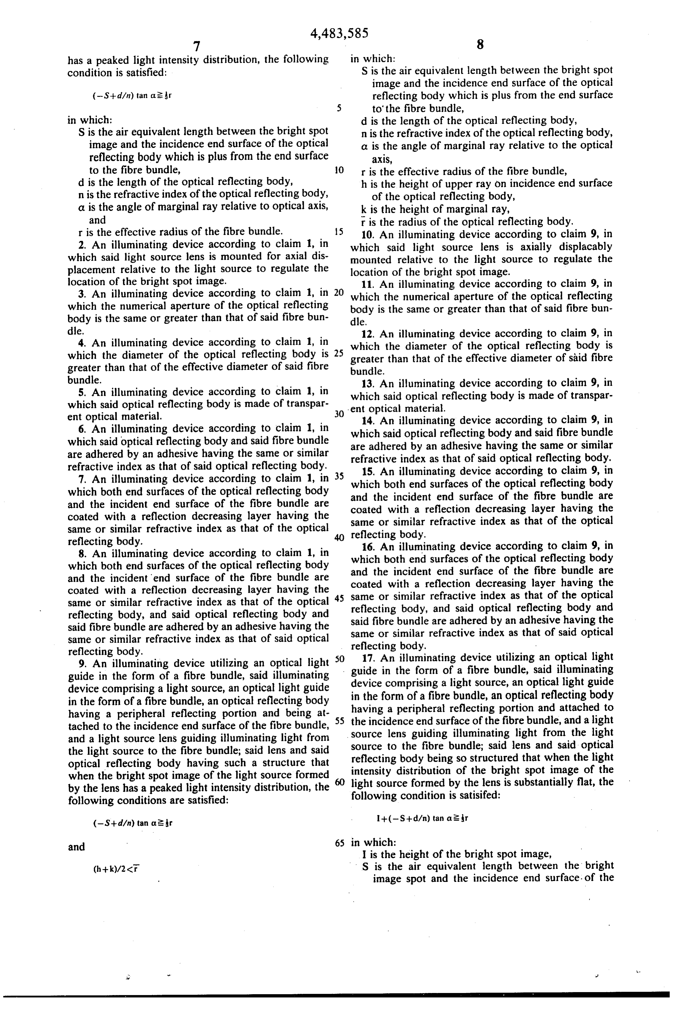
formulae (8) and (9), the illuminating device utilizing a fibre bundle connected with the single light guide 60 guide in the form of adevice 1. An illuminating utilizing an optical light causes the incident illuminating light to be substantially device comprising a lightfibre bundle, said illuminating source, an optical light guide uniformly distributed on the incidence end surface of in the form of a fibre bundle, an optical reflecting body the fibre bundle without causing light loss.
When light flux is not symmetrical with the optical the incidence end surface of theportion having a peripheral reflecting and attached to axis, for example, when a light stop is used, the values of 65 source lens guiding illuminating light fromand fibre bundle, the a light light h, k and a in the equations (2), (3), (4), (5), (7) and (8) source to the fibre bundle; said lens and said optical should adopt minimum values respectively. reflecting body having such a structure that when the The radius r of the core 17" of the single light guide bright spot image of the light source formed by the lens 17 may preferably be determined from the manufactur
Page 9
has a peaked light intensity distribution, the following in which:
condition is satisfied: S is the air equivalent length between the bright spot image and the incidence end surface of the optical (-S--d/n) tan a 2 r reflecting body which is plus from the end surface to' the fibre bundle, in which: d is the length of the optical reflecting body, S is the air equivalent length between the bright spot n is the refractive index of the optical reflecting body, image and the incidence end surface of the optical a is the angle of marginal ray relative to the optical reflecting body which is plus from the end surface aX1S, to the fibre bundle, O r is the effective radius of the fibre bundle, d is the length of the optical reflecting body, h is the height of upper ray on incidence end surface n is the refractive index of the optical reflecting body, of the optical reflecting body, a is the angle of marginal ray relative to optical axis, k is the height of marginal ray, and r is the radius of the optical reflecting body. r is the effective radius of the fibre bundle. 5 10. An illuminating device according to claim 9, in 2. An illuminating device according to claim 1, in which said light source lens is axially displacably which said light source lens is mounted for axial dis mounted relative to the light source to regulate the placement relative to the light source to regulate the location of the bright spot image.
location of the bright spot image. 11. An illuminating device according to claim 9, in 3. An illuminating device according to claim 1, in 20 which the numerical aperture of the optical reflecting which the numerical aperture of the optical reflecting body is the same or greater than that of said fibre bun body is the same or greater than that of said fibre bun dle.
dle. 12. An illuminating device according to claim 9, in 4. An illuminating device according to claim 1, in which the diameter of the optical reflecting body is which the diameter of the optical reflecting body is 25 greater than that of the effective diameter of said fibre greater than that of the effective diameter of said fibre bundle.
bundle. 13. An illuminating device according to claim 9, in 5. An illuminating device according to claim 1, in which said optical reflecting body is made of transpar which said optical reflecting body is made of transpar ent optical material.
ent optical material. 30 6. An illuminating device according to claim 1, in which 14. An illuminating device according to claim 9, in which said optical reflecting body and said fibre bundle are adhered said optical reflecting body and said fibre bundle are adhered by an adhesive having the same or similar refractive index by an adhesive having the same or similar refractive index as that of said optical reflecting body. 35 15. An illuminating as that of said optical reflecting body. 7. An illuminating device according to claim 1, in which both end surfacesdevice according to claim 9, in which both end surfaces of the optical reflecting body and the incident end surface ofoptical of the reflecting body the fibre bundle are and the incident end surface of the fibre bundle are coated with a reflection decreasing layer having the coated with a reflection decreasing layer having the same or similar refractive index as that of the optical same or similar refractive index as that of the optical 40 reflecting body.
reflecting body. 16. An illuminating device according to claim 9, in 8. An illuminating device according to claim 1, in which both end surfaces of the optical reflecting body which both end surfaces of the optical reflecting body and the incident end surface of the fibre bundle are and the incident end surface of the fibre bundle are coated with a reflection decreasing coated with a reflection decreasing layer having the 45 same or similar refractive index as that layer having the same or similar refractive index as that of the optical reflecting body, and said optical reflecting of the optical reflecting body, and said optical reflecting body and said fibre bundle are adhered by an adhesive having body and said fibre bundle are adhered by an adhesive having the same or similar refractive index as that of said optical the same or similar refractive index as that of said optical reflecting body.
reflecting body. 17. An illuminating device utilizing an optical light 9. An illuminating device utilizing an optical light 50 guide guide in the form of a fibre bundle, said illuminating deviceincomprisingthe form of a fibre bundle, said illuminating a light source, an optical light guide device comprising a light source, an optical light guide in the form of a fibre bundle, an optical reflecting body in the form of a fibre bundle, an optical reflecting body having a peripheral reflecting portion and attached to having a peripheral reflecting portion and being at the incidence end surface of the fibre bundle, and a light tached to the incidence end surface of the fibre bundle, 55 source and a light source lens guiding illuminating light from lens guiding illuminating light from the light the light source to the fibre bundle; said lens and said source to the fibre bundle; said lens and said optical reflecting body being so structured that when the light optical reflecting body having such a structure that intensity distribution when the bright spot image of the light source formed 60 light source formed byofthethelens bright spot image of the is substantially flat, the by the lens has a peaked light intensity distribution, the following conditions are satisfied: following condition is satisifed: (-S+d/n) tan a 2 r -- (-Si-d/n) tan a 2r
and 65 in which:
I is the height of the bright spot image,
S is the air equivalent length between the bright image spot and the incidence end surface. of the
Page 10
optical reflecting body which is plus from the end -- (-S-- dan) tan aer
d is the length of the optical reflecting body, n is the refractive index of the optical reflecting body, a is the angle of marginal ray relative to the optical 5 ax1S, in which:
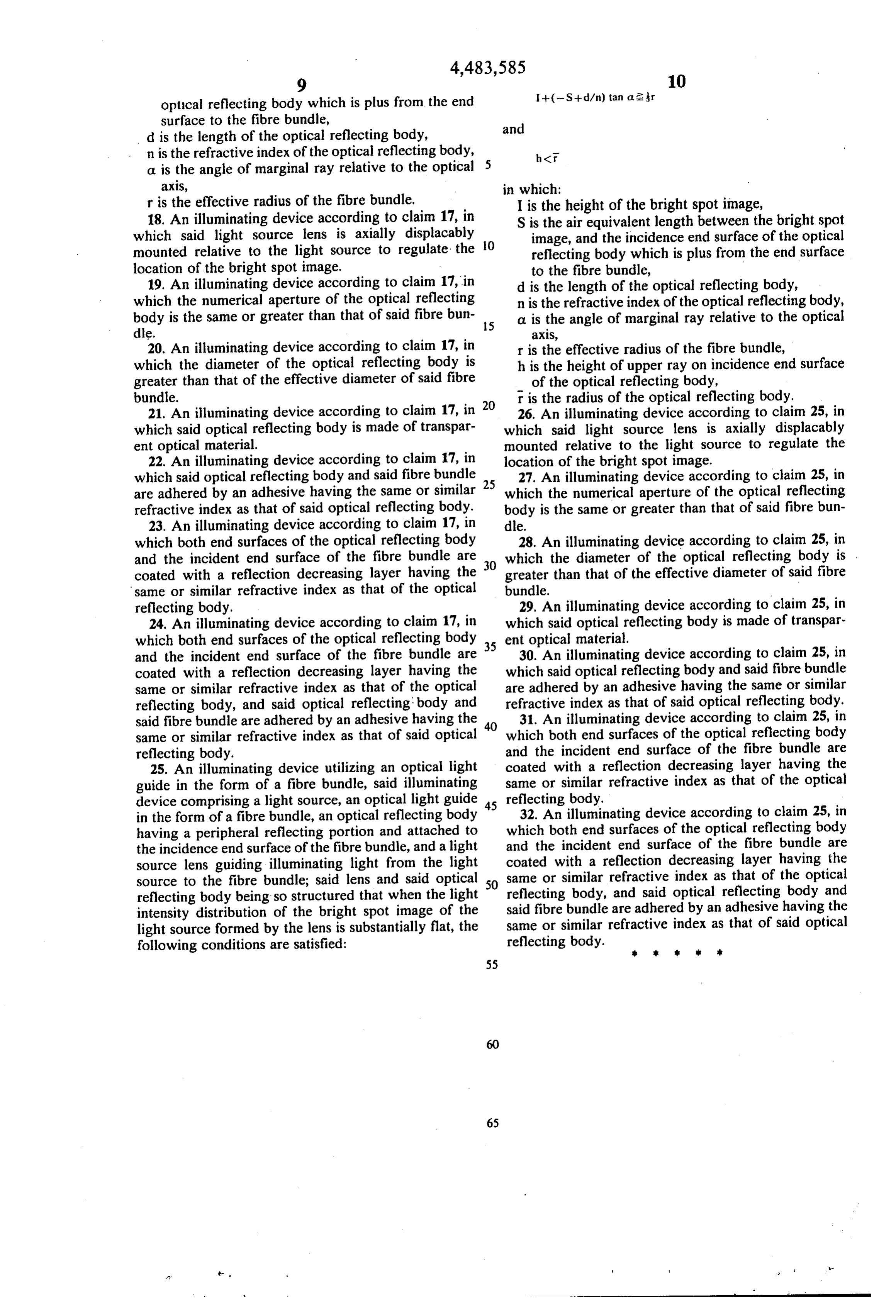
r is the effective radius of the fibre bundle, I is the height of the bright spot image, 18. An illuminating device according to claim 17, in S is the air equivalent length between the bright spot which said light source lens is axially displacably O image, and the incidence end surface of the optical mounted relative to the light source to regulate the reflecting body which is plus from the end surface location of the bright spot image. to the fibre bundle, 19. An illuminating device according to claim 17, in d is the length of the optical reflecting body, which the numerical aperture of the optical reflecting n is the refractive index of the optical reflecting body, body is the same or greater than that of said fibre bun 15 a is the angle of marginal ray relative to the optical dle. ax1S, 20. An illuminating device according to claim 17, in r is the effective radius of the fibre bundle, which the diameter of the optical reflecting body is h is the height of upper ray on incidence end surface greater than that of the effective diameter of said fibre of the optical reflecting body, bundle. 20 r is the radius of the optical reflecting body. 21. An illuminating device according to claim 17, in 26. An illuminating device according to claim 25, in which said optical reflecting body is made of transpar which said light source lens is axially displacably ent optical material. mounted relative to the light source to regulate the 22. An illuminating device according to claim 17, in location of the bright spot image.
which said optical reflecting body and said fibre bundle 27. An illuminating device according to claim 25, in are adhered by an adhesive having the same or similar 25 which the numerical aperture of the optical reflecting refractive index as that of said optical reflecting body. body is the same or greater than that of said fibre bun 23. An illuminating device according to claim 17, in dle.
which both end surfaces of the optical reflecting body 28. An illuminating device according to claim 25, in and the incident end surface of the fibre bundle are 30 which the diameter of the optical reflecting body is coated with a reflection decreasing layer having the greater than that of the effective diameter of said fibre same or similar refractive index as that of the optical bundle.
reflecting body. 29. An illuminating device according to claim 25, in 24. An illuminating device according to claim 17, in which said optical reflecting body is made of transpar which both end surfaces of the optical reflecting body 35 ent optical material.
and the incident end surface of the fibre bundle are 30. An illuminating device according to claim 25, in coated with a reflection decreasing layer having the which said optical reflecting body and said fibre bundle same or similar refractive index as that of the optical are adhered by an adhesive having the same or similar reflecting body, and said optical reflecting body and refractive index as that of said optical reflecting body. said fibre bundle are adhered by an adhesive having the 31. An illuminating device according to claim 25, in same or similar refractive index as that of said optical which both end surfaces of the optical reflecting body reflecting body. and the incident end surface of the fibre bundle are 25. An illuminating device utilizing an optical light coated with a reflection decreasing layer having the guide in the form of a fibre bundle, said illuminating same or similar refractive index as that of the optical device comprising a light source, an optical light guide 45 reflecting body.
in the form of a fibre bundle, an optical reflecting body 32. An illuminating device according to claim 25, in having a peripheral reflecting portion and attached to which both end surfaces of the optical reflecting body the incidence end surface of the fibre bundle, and a light and the incident end surface of the fibre bundle are source lens guiding illuminating light from the light coated with a reflection decreasing layer having the source to the fibre bundle; said lens and said optical 50 same or similar refractive index as that of the optical reflecting body being so structured that when the light reflecting body, and said optical reflecting body and intensity distribution of the bright spot image of the said fibre bundle are adhered by an adhesive having the light source formed by the lens is substantially flat, the same or similar refractive index as that of said optical following conditions are satisfied: reflecting body. it
Provenance
- Collection
- Cited prior art
- Original PDF
- patentimages.storage.googleapis.com →
- Filed
- 1982-11-24
- Pages
- 10
- Method
- pdftotext (the PDF's own text layer) + pdftoppm 300dpi page scans
- Source
- Google Patents bibliographic record
- Granted
- 1984-11-20
- Inventors
- Akiyoshi Takami; Olympus Optical Co Ltd
- Transcribed from
- patentimages.storage.googleapis.com →