patent · US5832168
Optical fiber light transfer apparatus
3 November 1998
Page 1 — bibliographic record
United States Patent (19) 11 Patent Number: 5,832,168 Yenter (45) Date of Patent: Nov. 3, 1998 54) OPTICAL FIBER LIGHT TRANSFER Primary Examiner John D. Lee APPARATUS ASSistant Examiner Juliana Kang Attorney, Agent, or Firm Duft, Graziano & Forest, P.C.
75 Inventor: Rex A. Yenter, Lakewood, Colo.
73 Assignee: Advance Display Technologies, Inc.,
Denver, Colo. A light transfer apparatus for transferring an image from a relatively Small projection Surface to a relatively large 21 Appl. No. 889,467 display Surface. The light transfer apparatus includes mod 22 Filed: Jul. 8, 1997 ules having a display surface, a light input Surface and a connection Surface. A plurality of modules are arranged So (51) Int. Cl." ....................................................... GO2B 6/08 that their respective display Surface combine to form the 52 U.S. Cl. .......................... 385/147; 38.5/116; 385/120; display Screen. The modules are connected to a frame by 385/901 Snapping each module onto a Support bar which is connected 58 Field of Search ..................................... 385/120, 116, to the frame. Optical fibers, which terminate on the surface 385/147, 901 of each module and extend from the light input Surface of each module, are positioned in a pigtail frame to form the 56) References Cited projection Surface. An image projected on the projection
The modular assembly design allows individual modules to 4,650,280 3/1987 Sedlmayr .................................. 350/96 be removed and replaced in the display Screen without 37.8 R R; m r: affecting any modules in addition to the replaced module. 4,929,048 5/1990 Cuypers .................................... 350/96 5,465,315 11/1995 Sakai et al. ............................. 385/120 13 Claims, 9 Drawing Sheets
Page 2
Drawing sheet — no readable text.
Page 3
Drawing sheet — no readable text.
Page 4
Drawing sheet — no readable text.
Page 5
Drawing sheet — no readable text.
Page 6
Drawing sheet — no readable text.
Page 7
Drawing sheet — no readable text.
Page 8
Drawing sheet — no readable text.
Page 9
Drawing sheet — no readable text.
Page 10
Drawing sheet — no readable text.
Page 11
OPTICAL FIBER LIGHT TRANSFER form a display screen. The system of the 730 patent APPARATUS includes a complicated arrangement of uniquely shaped modules arranged to cooperate with metal rods. The metal
FIELD OF THE INVENTION rods operate to connect adjacent modules into rows of The invention relates to the field of optical fiber light modules. The System, although effective to physically con transfer apparatus and a display Screen System utilizing nect modules together and to a frame, is complex and multiple optical fiber light transfer modules. expensive. There is no efficient way to remove a single module from the display Screen without dismantling the
PROBLEM entire display. There also is no way to carefully align rows of modules to help eliminate pixel offset between adjacent
There is a well-known need for the display of graphic or OWS.
Video information to large numbers of people in relatively U.S. Pat. No. 4,786,139 (the 139 patent) issued to large indoor or Outdoor Settings. Examples of Such large Sedlmayr on Nov. 22, 1988 also teaches an apparatus for Scale display applications include Schedule information to arranging multiple light transfer modules in a display Screen travelers in train Stations or airports, betting information to array. The system of the 139 patent is also complex and bettors in casinos and instant replay display in indoor or 15 expensive to produce. The system allows little flexibility in outdoor Stadiums and arenas. Although Smaller in Scale, alignment of modules or removal or replacement of mod residential television applications now are Such that conven ules.
tional cathode ray tube technology is not appropriate or even There exists a need for optical fiber light transfer display possible for Some applications. Screen System that is relatively simple to construct from a There are many existing optical fiber-based large Scale plurality of optical fiber light transfer modules. There also display Systems based on a modular design. These existing exists a need to flexibly adjust the pixel offset between rows Systems make use of a relatively Small display module. of the display Screen System. There exists an additional need Multiple Such modules are arrayed to form a display Screen. for a display Screen System that provides for relatively Existing Such Systems are complicated in design and difficult 25 Seamless alignment between adjacent light transfer modules. and expensive to manufacture rendering them economically prohibitive for widespread commercial use. SOLUTION A further problem of existing modular display Systems is The above-described problems and others are solved and that the image displayed on the display Screen can appear an advance in the art is thereby achieved by the display Segmented both vertically and horizontally. This is because Screen System of the present invention. The display Screen the Overall display is formed, as noted above, from multiple System of the present invention provides a simple, rugged modules. This effect is sometimes referred to as the “shingle and flexible apparatus and method for arranging multiple effect”. The interfaces between each module appear as light transfer modules into a display Screen. Rows of light distinct lines. This occurs for a variety of reasons. Physical transfer modules are individually adjustable to eliminate mismatching between the edge of a module with respect to 35 pixel offset between rows. The light transfer modules them the adjacent edges of the neighboring modules is visible as Selves are designed to provide a relatively SeamleSS align distinct lines on the display Surface. In fact, the human eye ment between light transfer modules thus exhibiting little or is quite adept at discerning Such incongruities in a display no shingle effect. The result is a large-scale display Screen Screen Surface and resolving Such incongruities as lines on having unprecedented ease of assembly, flexibility of adjust the display Surface. Another Source of discontinuities in the 40 ment and continuity of the displayed image. display Screen Surface is that multiple rows of modules may The System of the present invention is comprised, in part, not perfectly align pixel for pixel with adjacent rows of by a frame on which the light transfer modules are mounted. modules. Any horizontal variation in position between the Each light transfer module is formed to Snap into place on pixels of one module with respect to a module located above a mounting bar that extends acroSS the width of the frame. or below the first module is again resolved by the human eye 45 There is one Such mounting bar for each row of light transfer as a discontinuity in the display Screen Surface. modules which comprise the display Screen. Each row of U.S. Pat. No. 4,650,280 (the 280 patent) issued to light transfer modules is horizontally adjustable by the Sedlmayr on Mar. 17, 1987 describes a modular fiber optic manipulation of adjustment blockS Secured to the frame at light transfer module. A ribbon of optical fibers are fixed in each end of each row of light transfer modules. The rows of a plastic spacer. Multiple Spacers are Stacked to produce a 50 light transfer modules are adjusted using the adjustment module having rows of optical fibers which terminate on a blocks to eliminate any offset in the pixel alignment from viewing surface of the display module. The other ends of the one row to the next. Once aligned, each individual light optical fibers are gathered into relatively Small array onto transfer module is Securely mounted to the mounting bar which is projected an image. The image is transferred with a mounting bracket.
through the optical fibers to the relatively large Surface of the 55 Each light transfer module Seamlessly aligns with verti display Screen. The 280 patent does not provide a high pixel cally adjacent light transfer modules through cooperating contrast ratio Since the optical fibers are aligned in a ribbon Vertical mating Surfaces on the top and bottom of each light format. Therefore there is no space between individual transfer module. The result is the reduction or elimination of pixels. Also, the 280 patent does not provide an apparatus any visible line or discontinuity between Vertically adjoining for fixing multiple Such modules in a fixed, adjacent rela 60 light transfer modules.
tionship to develop a large display Screen. Also, the 280 Individual light transfer modules are not connected to patent does not address the issue of eliminating any discon other light transfer modules. This allows the removal, inser tinuities in the displayed image due to inconsistencies tion or replacement of Single light transfer modules to and between the multiple modules. from a complete display Screen System without the need to U.S. Pat. No. 4,773,730 (the 730 patent) issued to 65 dismantle the entire System.
Sedlmayr on Sep. 27, 1988 describes an apparatus for The System of the present invention provides a simple, connecting a plurality of fiber optic light transfer modules to efficient and flexible large Scale display Screen System.
Page 12
Although most of the detailed description is made with of the optical fibers terminated on display screen 101. For respect to a display Screen System where light is projected example, an optical fiber terminating at one end in the upper from a Video projector of Some type, the invention is also right-most corner of display Screen 101 terminates at its useful in other applications. For example, one might mate other end in the upper right-most corner of projection the ends of the optical fibers to Light Emitting Diode Surface 201.
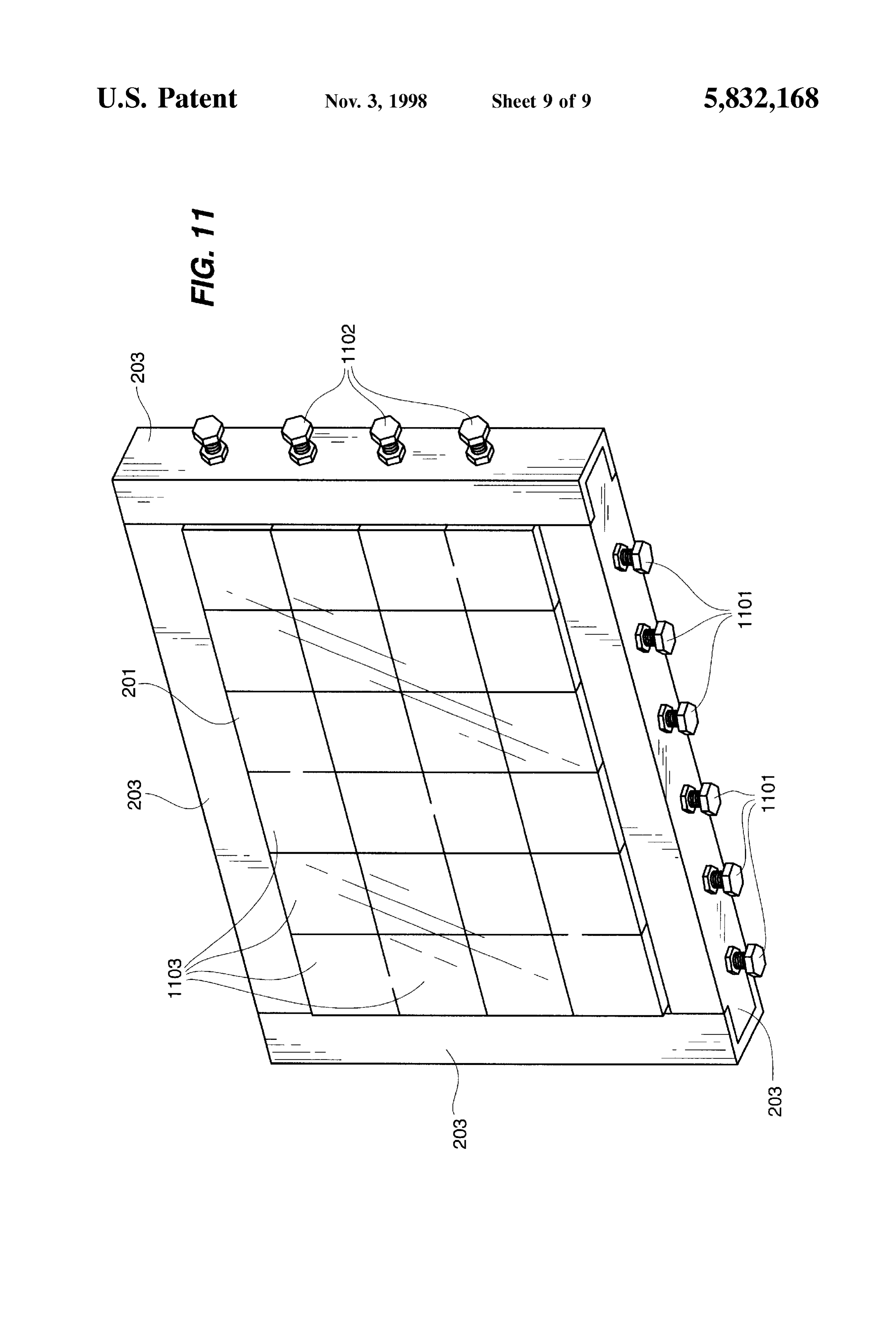
(“LED") arrays which are stimulated by a video processing Light projector 104 projects an image onto projection System to emit appropriately colored light directly into one surface 201. The projected image is transferred by the end of the optical fibers for display on the display Screen transmission of light through the optical fibers. The pro Surface. jected light is emitted at display screen 101 from the ends of Other Salient features, objects, and advantages will be the optical fibers terminating at the display Screen. Optical apparent to those skilled in the art upon a reading of the fiber guide 200 serves to guide the optical fibers to the discussion below in combination with the accompanying projection surface 201 and pigtail frame 203, described in drawings. more detail with respect to FIG. 11, operates to hold the optical fibers in the proper orientation at the projection
BRIEF DESCRIPTION OF THE DRAWINGS 15 Surface 201.
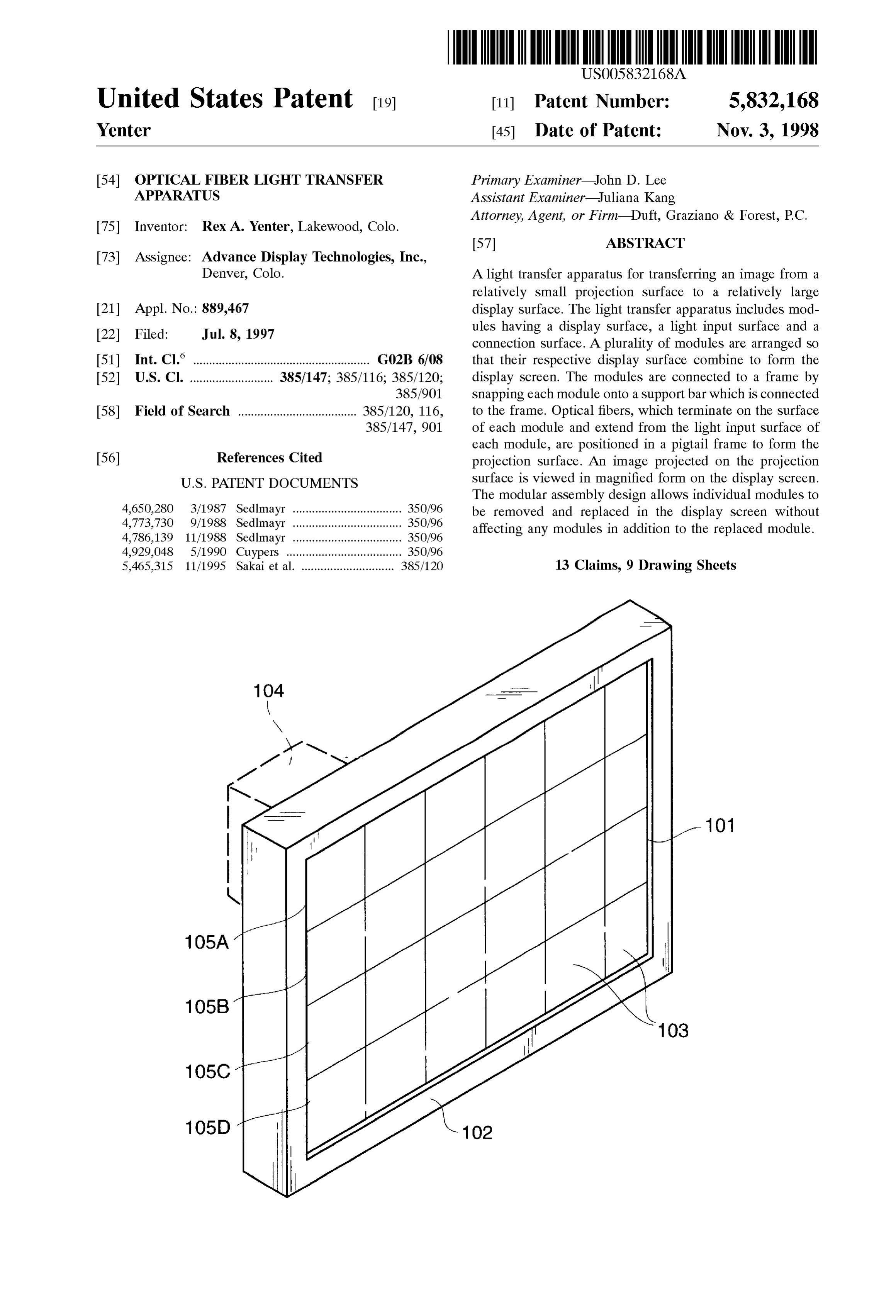
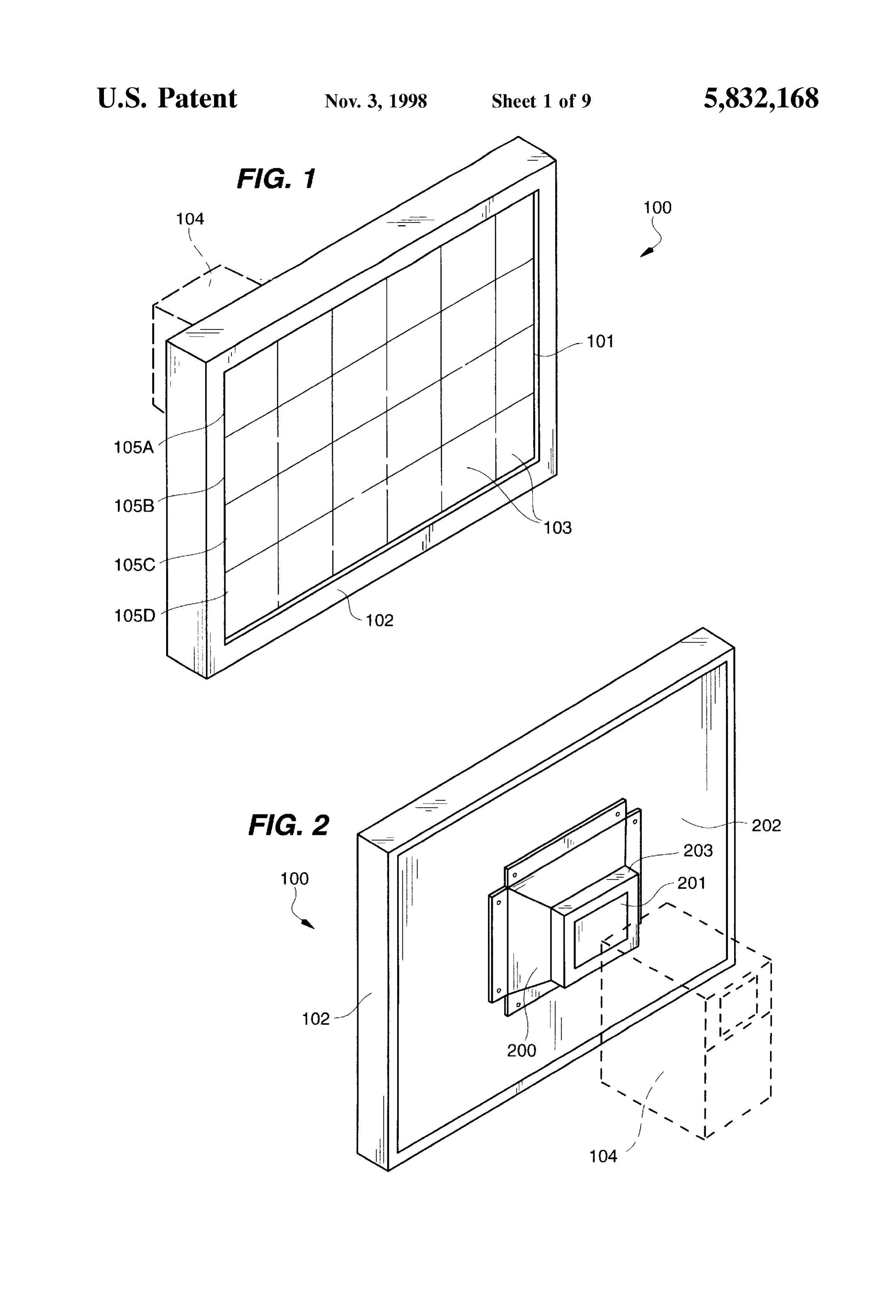
FIG. 1 is a front perspective view of a complete modular Light projector 104 is any kind of light projection device display Screen System according to the present invention; delivering light of Sufficient intensity that the light is trans mitted to display screen 101 and is visible to the viewer.
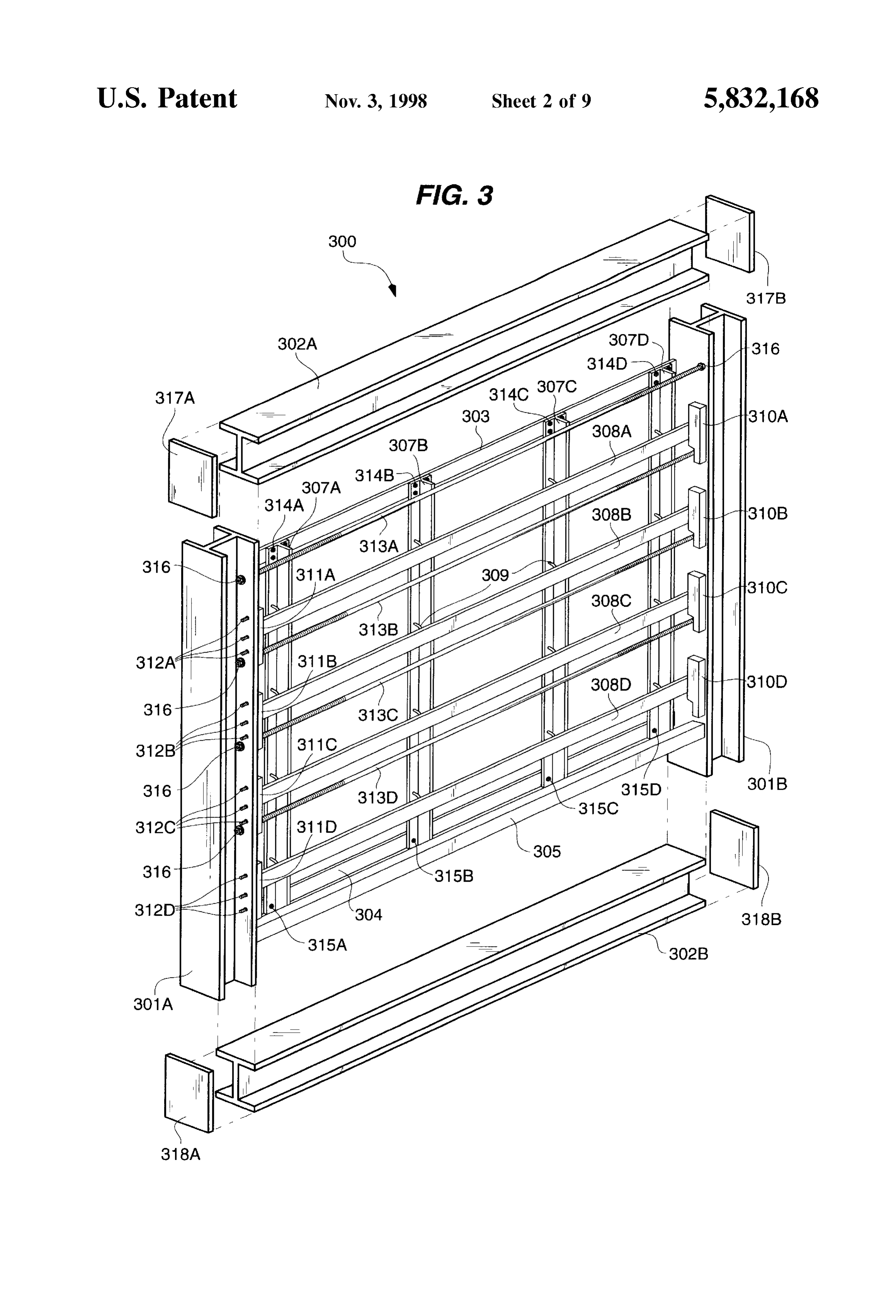
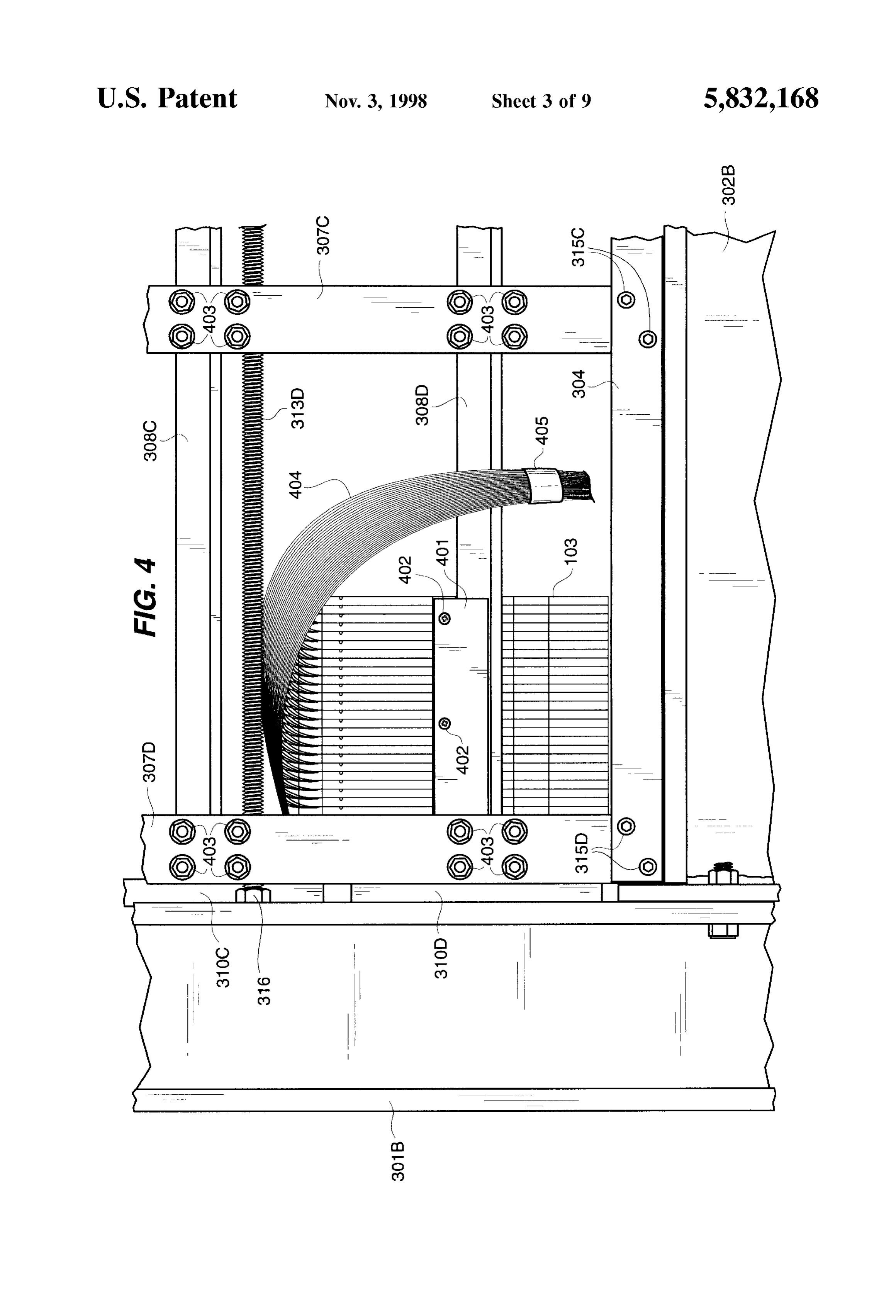
FIG. 2 is a rear perspective view of a complete modular Display System Frame-FIG. 3-4 display Screen System according to the present invention; FIG. 3 illustrates display screen frame 300. Display FIG. 3 is a front perspective view of a frame assembly for screen frame 300 is formed from a border comprised by left a display Screen System according to the present invention; I-beam 301A, right I-beam 301B, top I-beam 302A and FIG. 4 is a rear view of a portion of the frame assembly bottom I-beam 302B. I-beams 301A-301B and 302A-302B for a display Screen System showing one installed light are formed from aluminum H-beam to provide a rigid and transfer module; 25 relatively light structure for display screen frame 300. Top FIG. 5 is a front perspective view of a single light transfer rail 303 and bottom rail 304 are preferably formed from steel module, bar stock. End-caps 317A-317B are weld to their respective ends of top I-beam 302A. Top I-beam 302A is fixedly
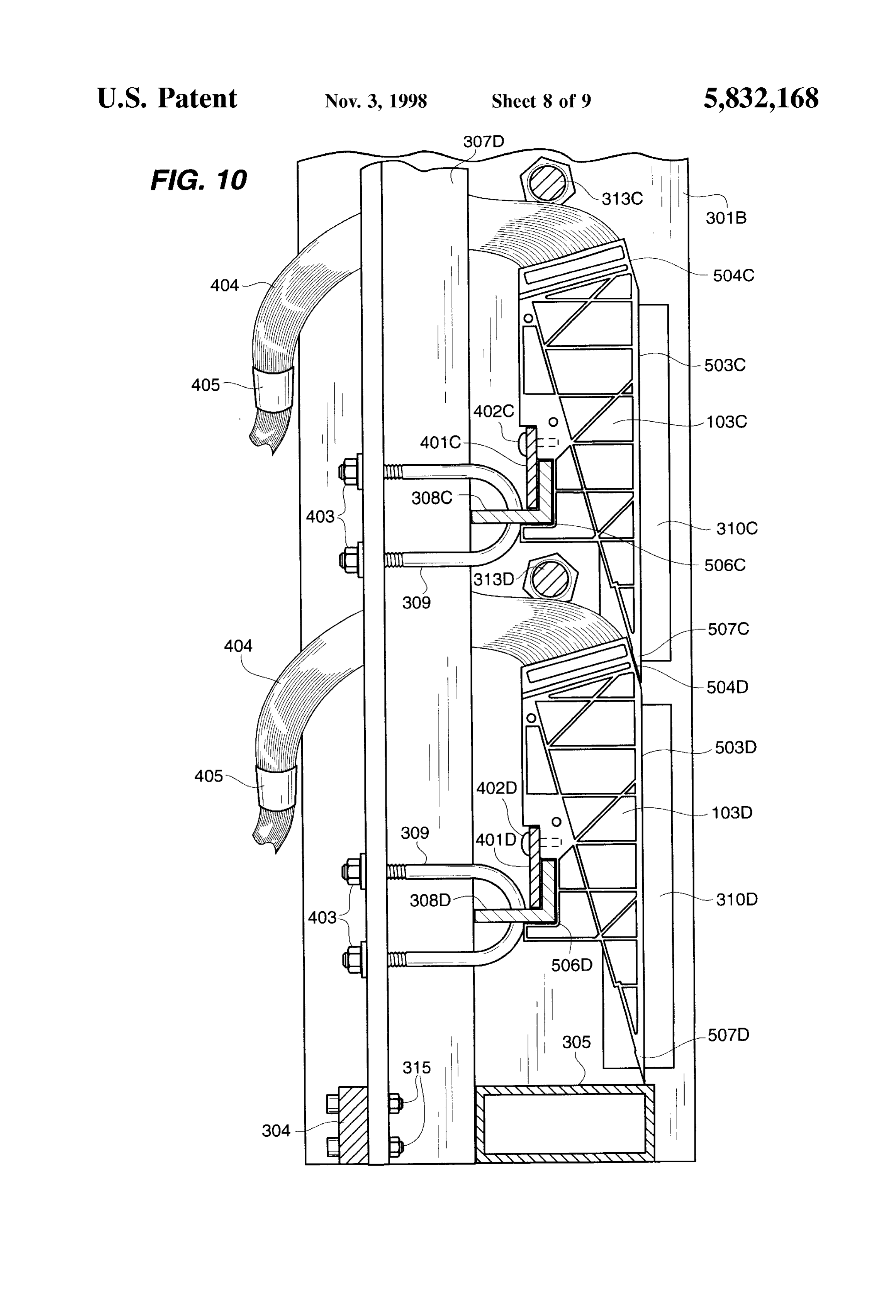
FIG. 6 is a perspective view of a full stack of light transfer attached to side I-beams 301A-301B with bolts (not shown) module Spacers, passing through end-caps 317A-317B and side I-beams FIG. 7 is a front perspective view of a light transfer 301A-301B. Bottom support 305 is also fixedly connected module Spacer according to the present invention; between side I-beams 301A-301B. Those skilled in the art FIG. 8 is a detail showing the optical fiber placed in the recognize that Screen frame 300 could be comprised of light transfer module Spacer, different materials and different shaped materials than those FIG. 9 is a rear view of a light transfer module spacer 35 described with respect to the preferred embodiment. Screen according to the present invention; frame 300 need only be formed of materials sufficient to FIG. 10 is side cross-sectional view of two light transfer Support the weight of the display Screen without deforming modules connected to the display Screen frame. under the forces necessary to assemble the display Screen FIG. 11 depicts a pigtail frame for holding the ends of 40 and without degrading over time. Aluminum has been used optical fiber pigtails to form a projection Surface. for many of the frame components in the preferred embodi ment because of its advantageous combination of weight and
Display Screen System in General-FIGS. 1-2 T-bars 307A-307D are arranged vertically between top FIGS. 1-2 generally illustrate a complete display Screen rail 303 and bottom rail 304. T-bars 307A-307D are fixedly system 100 according to the present invention. For all of 45 connected to top rail 303 using bolts 314A-314D and to FIGS. 1-10, elements visible in one FIG. that are common bottom rail 304 using bolts 315A-315D. Module support to another FIG. are referenced by common reference numer bars 308A-308D are arranged horizontally between side als in all FIGS. Display screen system 100 is comprised of I-beams 301A-301B. Module support bars 308A-308D are display screen 101 Surrounded by frame cover 102. Display not fixedly connected to side I-beams 301A-301B. At each screen 101 is comprised of a plurality of light transfer 50 location of intersection between one of T-bars 307A-307D modules 103 arranged in columns and rows. The size of each and one of module support bars 308A-308D, two U-bolts light transfer module 103 is of course variable to meet 309 attached to the T-bar pass through holes (not shown in design requirements. In a preferred embodiment of the FIG. 3) on the module support bar. U-bolts 309 secure present invention each light transfer module 103 is 6"x6". module support bars 308A-308D to the T-bars 307A-307D. These dimensions for light transfer module 103 provide a 55 In the view of FIG.3 only a portion of one of the two U-bolts display screen size, for the example of FIGS. 1-2 of 3' wide 309 can be seen at each intersection of T-bars 307A-307D by 2' tall. AS apparent to those skilled in the art, the size of and module support bars 308A-308D. Only two of U-bolts the display Screen of the present invention is Scalable to any 309 are identified with reference with numerals in FIG. 3 but desired size. those skilled in the art recognize the similar use of U-bolts A plurality of optical fibers (not shown in FIGS. 1-2) are 60 309 across display screen frame 300.
arranged in each light transfer module. One end of each As described in more detail with respect to FIGS. 4 and optical fiber terminates on display screen 101 and the other 10, each light transfer module 103 (not shown in FIG. 3) end of each optical fiber terminates on projection Surface attaches to frame 300 by Snapping into place on module 201. One end of each fiber in every light transfer module of support bars 308A-308D. Horizontal adjustment blocks display system 100 terminates at projection surface 201. The 65 310A-310D and horizontal adjustment blocks 311A-311D fibers at projection Surface 201 are arranged in an array to bound each row of light transfer modules. For example, with maintain the same relative relationship held by the other end reference to FIG. 1, row 105A of light transfer modules 103
Page 13
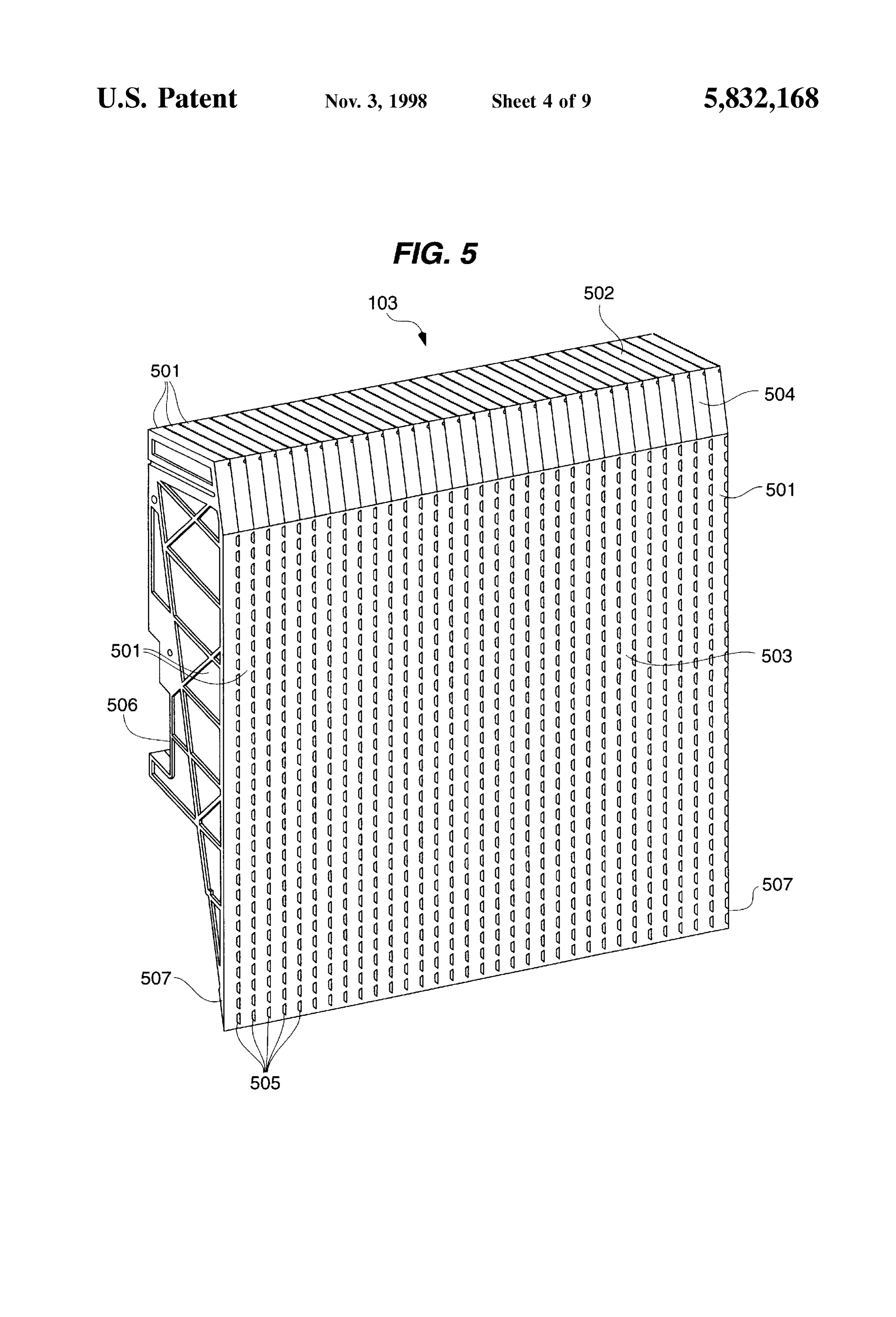
S 6 is bounded on the left side of frame 300 by horizontal in turn fixedly attached to bottom I-beam 302B. Module adjustment block 311A and on the right side of frame 300 by support bars 308C and 308D are connected to T-bars horizontal adjustment block 310A. The light transfer mod 307C-307D with U-bolts 309 (not visible in FIG. 4) and ules 103 adjacent to horizontal adjustment blocks nuts 403. A portion of frame Support element 313D is shown 310A-310D and 311A-311D are not fixedly attached to the connected through nut 316 to side I-beam 301B. Light horizontal adjustment block. Horizontal adjustment blockS transfer module 103 is slidably connected to module Support 310A-310D and 311A-311D exert a force against each row bar 308D. Before module bracket 401 is tightened, light of light transfer modules 103. The position of horizontal transfer module 103 can be moved along module support bar adjustment blocks 311A-311D is adjusted using adjustment 308D by the adjustment of horizontal adjustment block screws 312A-312D. A similar set of adjustment screws (not 310D module as described with respect to FIG.3. Once light transfer 103 is properly positioned along module Support bar visible in FIG. 3) is similarly associated with adjustment 308D, module bracket 401 is tightened using screws 402 to blocks 310A-310D. Adjustment screws 312A extend hold light transfer module 103 in place. Screws 402 pass through left I-beam 301A and cooperate with horizontal through module bracket 401 and into the rear surface of light adjustment block 311A. When adjustment screws 312A are transfer module 103. Fiber pigtail 404 from light transfer turned clock-wise, horizontal adjustment block 311A is 15 module 103 is drawn together by tie 405. caused to move to the right with respect to FIG. 3. Adjust Light Transfer Module-FIGS. 5–9 ment screws 312B-312D cooperate to move horizontal FIG. 5 shows a single light transfer module 103. Each adjustment blocks 311B-311D in similar fashion. light transfer module 103 is built from multiple half-spacers The horizontal adjustment of row 105A of display screen 501 as described below. Light transfer module 103 has 101 is described as exemplary of the horizontal adjustment pigtail surface 502, display Surface 503 and vertical mating flexibility of the display screen of the present invention. surface 504. The extreme lower portion of light transfer When all of light transfer modules 103 making up row 105A module 103 extending across the full width of light transfer have been installed on module support bar 308A, horizontal module 103 is mating lip 507. Mating lip 507 is discussed adjustment blocks 310A and 311A are adjusted to firmly in more detail with respect to FIG. 10. In a preferred press against their respective ends of row 105A. When it is 25 embodiment of the present invention, illustrated in FIGS. determined upon fully assembling display screen 101 that 5-9, 32 half spacers 501 are combined to form a light the pixel elements (discussed below with respect to FIG.9) transfer module 103. Each half spacer 501 is formed, as of row 105A are misaligned to the left, for example, of the described below with respect to FIGS. 7-8, to accept and pixel elements of row 105B, then row 105A must be hold 32 optical fibers (not shown in FIG. 5). This configu adjusted horizontally. The adjustment Screws associated ration results in 1024 pixels 505 on display surface 503. with horizontal adjustment block 310A are turned a number Each pixel 505 is the termination of one optical fiber on of turns counter-clockwise. This causes horizontal adjust display surface 503.
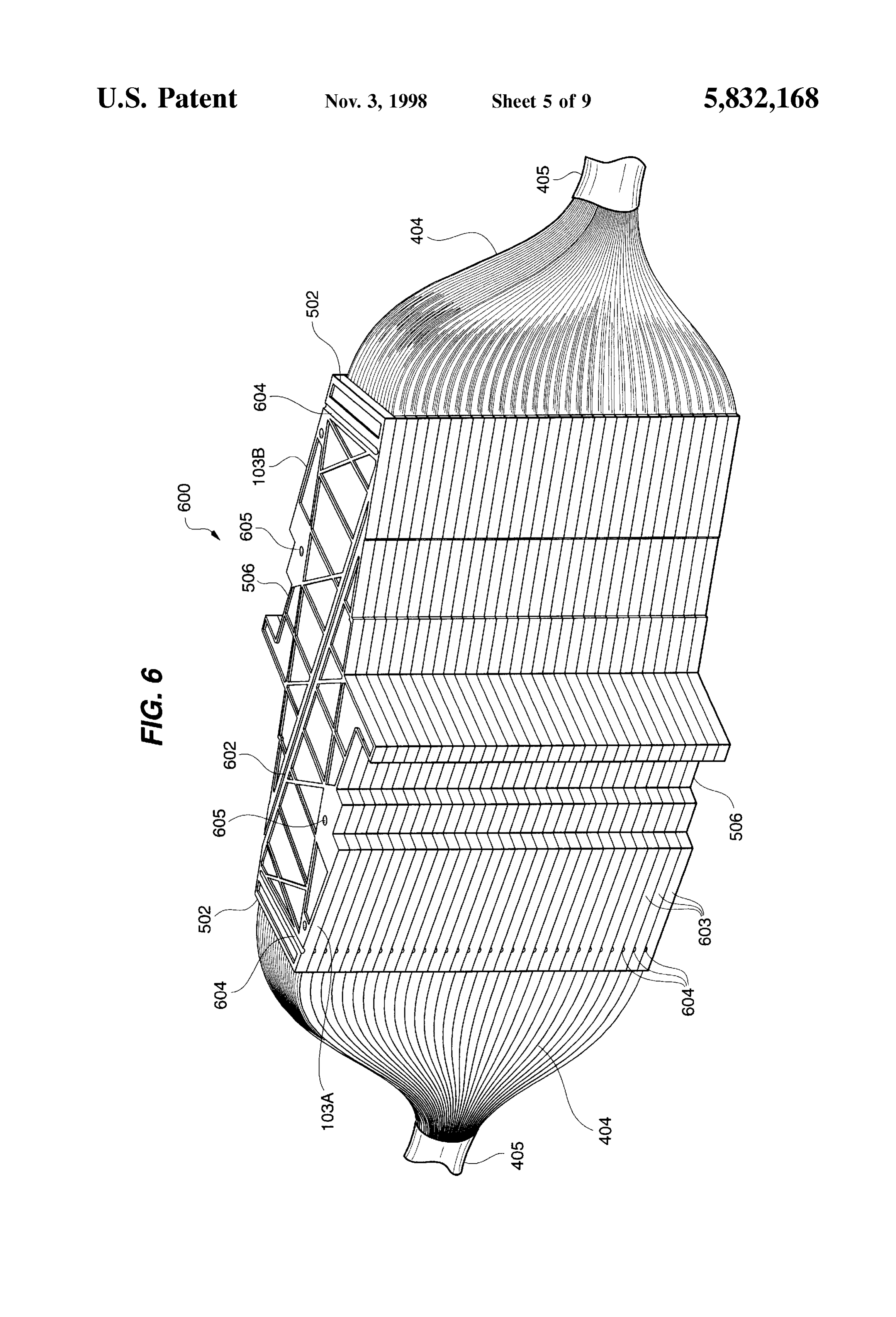
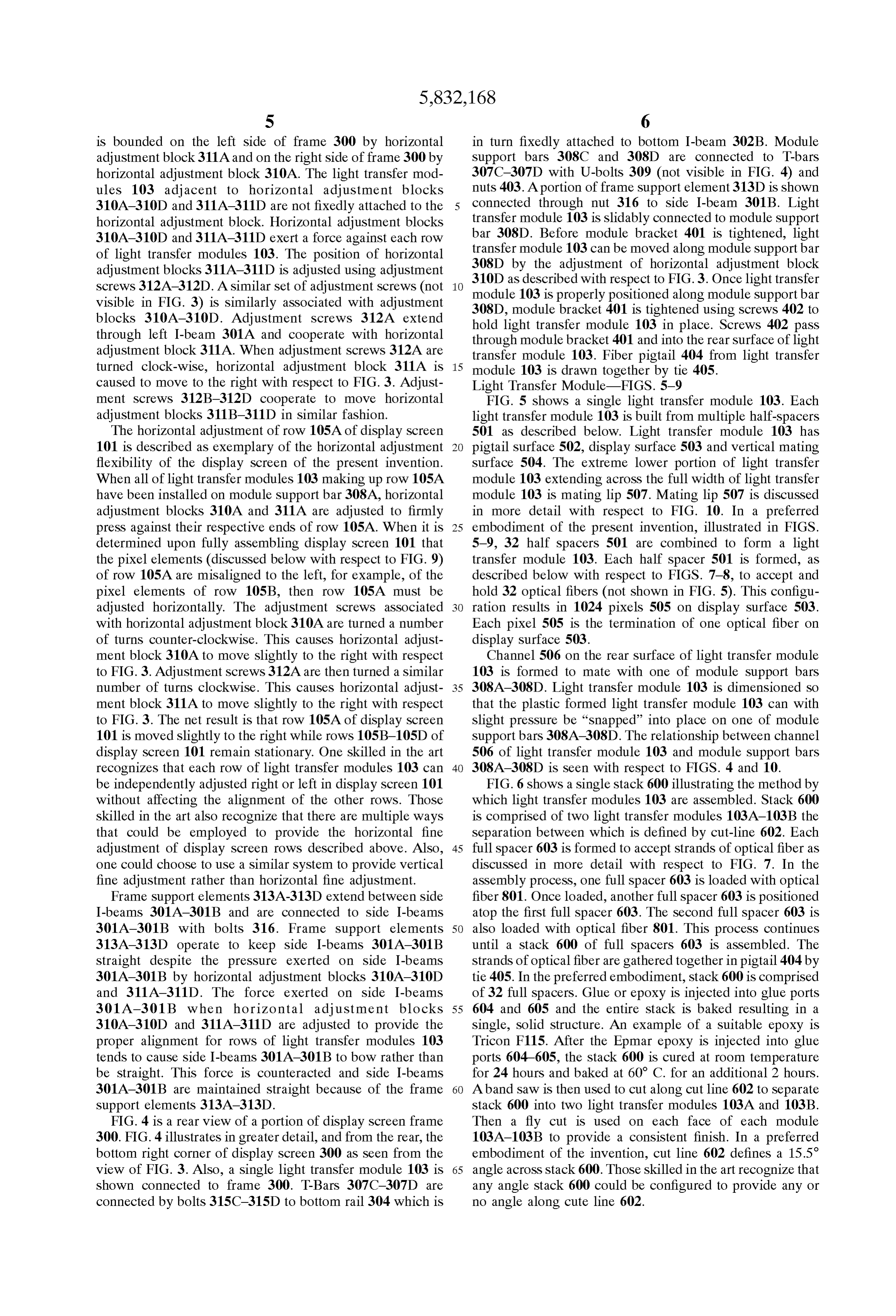
ment block 310A to move slightly to the right with respect Channel 506 on the rear Surface of light transfer module to FIG. 3. Adjustment screws 312A are then turned a similar 103 is formed to mate with one of module Support bars number of turns clockwise. This causes horizontal adjust 35 308A-308D. Light transfer module 103 is dimensioned so ment block 311A to move slightly to the right with respect that the plastic formed light transfer module 103 can with to FIG. 3. The net result is that row 105A of display screen Slight pressure be "Snapped' into place on one of module 101 is moved slightly to the right while rows 105 B-105D of support bars 308A-308D. The relationship between channel display screen 101 remain stationary. One skilled in the art 506 of light transfer module 103 and module support bars recognizes that each row of light transfer modules 103 can 40 308A-308D is seen with respect to FIGS. 4 and 10. be independently adjusted right or left in display screen 101 FIG. 6 shows a single stack 600 illustrating the method by without affecting the alignment of the other rows. Those which light transfer modules 103 are assembled. Stack 600 skilled in the art also recognize that there are multiple ways is comprised of two light transfer modules 103A-103B the that could be employed to provide the horizontal fine separation between which is defined by cut-line 602. Each adjustment of display Screen rows described above. Also, 45 full spacer 603 is formed to accept strands of optical fiber as one could choose to use a similar System to provide vertical discussed in more detail with respect to FIG. 7. In the fine adjustment rather than horizontal fine adjustment. assembly process, one full spacer 603 is loaded with optical Frame Support elements 313 A-313D extend between side fiber 801. Once loaded, another full spacer 603 is positioned I-beams 301A-301B and are connected to side I-beams atop the first full spacer 603. The second full spacer 603 is 301A-301B with bolts 316. Frame support elements 50 also loaded with optical fiber 801. This process continues 313A-313D operate to keep side I-beams 301A-301B until a stack 600 of full spacers 603 is assembled. The Straight despite the pressure exerted on Side I-beams Strands of optical fiber are gathered together in pigtail 404 by 301A-301 B by horizontal adjustment blocks 310A-310D tie 405. In the preferred embodiment, stack 600 is comprised and 311A-311D. The force exerted on side I-beams of 32 full spacers. Glue or epoxy is injected into glue ports 301 A-301 B when horizontal adjustment blocks 55 604 and 605 and the entire stack is baked resulting in a 310A-310D and 311A-311D are adjusted to provide the Single, Solid structure. An example of a Suitable epoxy is proper alignment for rows of light transfer modules 103 Tricon F115. After the Epmar epoxy is injected into glue tends to cause side I-beams 301A-301B to bow rather than ports 604-605, the stack 600 is cured at room temperature be straight. This force is counteracted and Side I-beams for 24 hours and baked at 60° C. for an additional 2 hours. 301A-301B are maintained straight because of the frame 60 Aband Saw is then used to cut along cut line 602 to Separate support elements 313A-313D. stack 600 into two light transfer modules 103A and 103B. FIG. 4 is a rear view of a portion of display screen frame Then a fly cut is used on each face of each module 300. FIG. 4 illustrates in greater detail, and from the rear, the 103A-103B to provide a consistent finish. In a preferred bottom right corner of display screen 300 as seen from the embodiment of the invention, cut line 602 defines a 15.5 view of FIG. 3. Also, a single light transfer module 103 is 65 angle across stack 600. Those skilled in the art recognize that shown connected to frame 300. T-Bars 307C-307D are any angle Stack 600 could be configured to provide any or connected by bolts 315C-315D to bottom rail 304 which is no angle along cute line 602.
Page 14
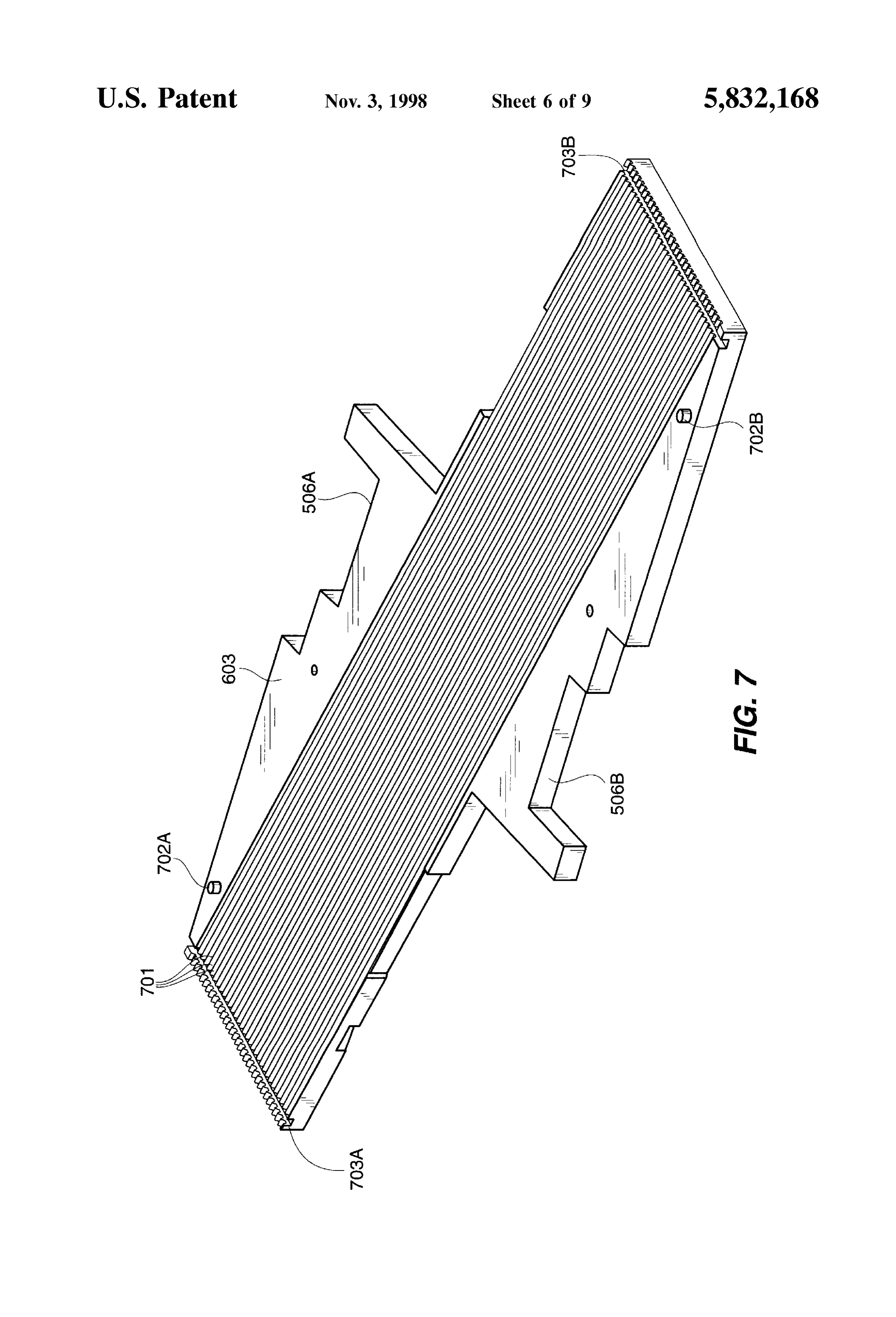
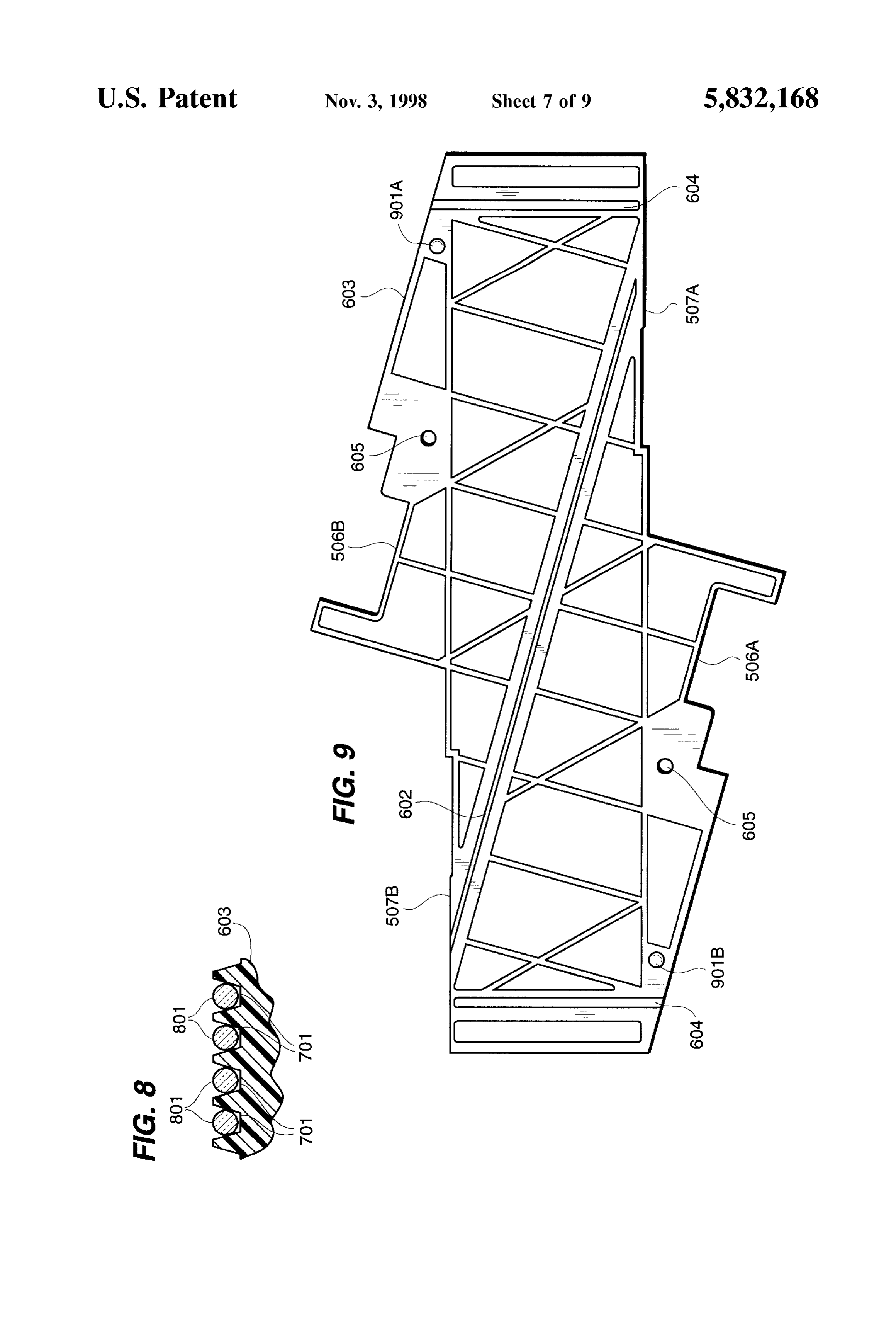
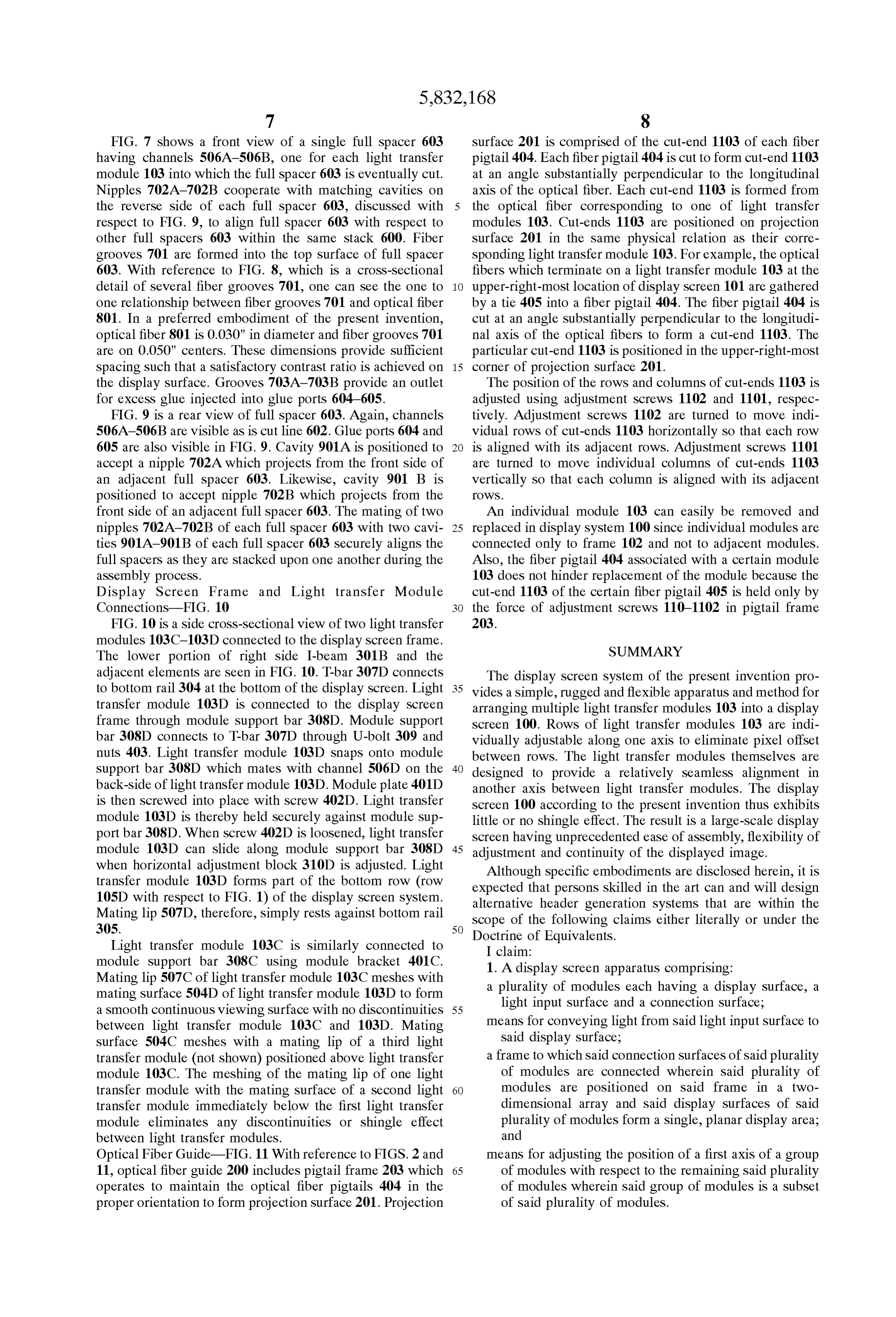
FIG. 7 shows a front view of a single full spacer 603 surface 201 is comprised of the cut-end 1103 of each fiber having channels 506A-506B, one for each light transfer pigtail 404. Each fiber pigtail 404 is cut to form cut-end 1103 module 103 into which the full spacer 603 is eventually cut. at an angle Substantially perpendicular to the longitudinal Nipples 702A-702B cooperate with matching cavities on axis of the optical fiber. Each cut-end 1103 is formed from the reverse side of each full spacer 603, discussed with the optical fiber corresponding to one of light transfer respect to FIG. 9, to align full spacer 603 with respect to modules 103. Cut-ends 1103 are positioned on projection other full spacers 603 within the same stack 600. Fiber Surface 201 in the same physical relation as their corre grooves 701 are formed into the top surface of full spacer sponding light transfer module 103. For example, the optical 603. With reference to FIG. 8, which is a cross-sectional fibers which terminate on a light transfer module 103 at the detail of several fiber grooves 701, one can see the one to upper-right-most location of display Screen 101 are gathered one relationship between fiber grooves 701 and optical fiber by a tie 405 into a fiber pigtail 404. The fiber pigtail 404 is 801. In a preferred embodiment of the present invention, cut at an angle Substantially perpendicular to the longitudi optical fiber 801 is 0.030" in diameter and fiber grooves 701 nal axis of the optical fibers to form a cut-end 1103. The are on 0.050" centers. These dimensions provide sufficient particular cut-end 1103 is positioned in the upper-right-most spacing Such that a Satisfactory contrast ratio is achieved on 15 corner of projection Surface 201. the display surface. Grooves 703A-703B provide an outlet The position of the rows and columns of cut-ends 1103 is for excess glue injected into glue ports 604-605. adjusted using adjustment screws 1102 and 1101, respec FIG. 9 is a rear view of full spacer 603. Again, channels tively. Adjustment screws 1102 are turned to move indi 506A-506B are visible as is cut line 602. Glue ports 604 and vidual rows of cut-ends 1103 horizontally so that each row 605 are also visible in FIG. 9. Cavity 901A is positioned to is aligned with its adjacent rows. Adjustment screws 1101 accept a nipple 702A which projects from the front side of are turned to move individual columns of cut-ends 1103 an adjacent full spacer 603. Likewise, cavity 901 B is Vertically So that each column is aligned with its adjacent positioned to accept nipple 702B which projects from the OWS.
front side of an adjacent full spacer 603. The mating of two An individual module 103 can easily be removed and nipples 702A-702B of each full spacer 603 with two cavi 25 replaced in display system 100 since individual modules are ties 901A-901B of each full spacer 603 securely aligns the connected only to frame 102 and not to adjacent modules. full Spacers as they are Stacked upon one another during the Also, the fiber pigtail 404 associated with a certain module assembly process. 103 does not hinder replacement of the module because the Display Screen Frame and Light transfer Module cut-end 1103 of the certain fiber pigtail 405 is held only by Connections-FIG. 10 the force of adjustment screws 110-1102 in pigtail frame FIG. 10 is a side cross-sectional view of two light transfer 2O3.
modules 103C-103D connected to the display screen frame. SUMMARY The lower portion of right side I-beam 301B and the adjacent elements are seen in FIG. 10. T-bar 307D connects The display Screen System of the present invention pro to bottom rail 304 at the bottom of the display screen. Light 35 vides a simple, rugged and flexible apparatus and method for transfer module 103D is connected to the display screen arranging multiple light transfer modules 103 into a display frame through module support bar 308D. Module support screen 100. Rows of light transfer modules 103 are indi bar 308D connects to T-bar 307D through U-bolt 309 and vidually adjustable along one axis to eliminate pixel offset nuts 403. Light transfer module 103D Snaps onto module between rows. The light transfer modules themselves are support bar 308D which mates with channel 506D on the 40 designed to provide a relatively Seamless alignment in back-side of light transfer module 103D. Module plate 401D another axis between light transfer modules. The display is then screwed into place with screw 402D. Light transfer screen 100 according to the present invention thus exhibits module 103D is thereby held securely against module Sup little or no shingle effect. The result is a large-scale display port bar 308D. When screw 402D is loosened, light transfer Screen having unprecedented ease of assembly, flexibility of module 103D can slide along module Support bar 308D 45 adjustment and continuity of the displayed image. when horizontal adjustment block 310D is adjusted. Light Although specific embodiments are disclosed herein, it is transfer module 103D forms part of the bottom row (row expected that perSons skilled in the art can and will design 105D with respect to FIG. 1) of the display screen system. alternative header generation Systems that are within the Mating lip 507D, therefore, simply rests against bottom rail Scope of the following claims either literally or under the
Doctrine of Equivalents.
Light transfer module 103C is similarly connected to I claim:
module Support bar 308C using module bracket 401C. 1. A display Screen apparatus comprising: Mating lip 507C of light transfer module 103C meshes with a plurality of modules each having a display Surface, a mating surface 504D of light transfer module 103D to form light input Surface and a connection Surface; a Smooth continuous viewing Surface with no discontinuities 55 between light transfer module 103C and 103D. Mating means for conveying light from Said light input Surface to surface 504C meshes with a mating lip of a third light Said display Surface;
transfer module (not shown) positioned above light transfer a frame to which said connection Surfaces of Said plurality module 103C. The meshing of the mating lip of one light of modules are connected wherein Said plurality of transfer module with the mating Surface of a Second light 60 modules are positioned on Said frame in a two transfer module immediately below the first light transfer dimensional array and Said display Surfaces of Said module eliminates any discontinuities or Shingle effect plurality of modules form a single, planar display area; between light transfer modules. and
Optical Fiber Guide-FIG.11 With reference to FIGS. 2 and means for adjusting the position of a first axis of a group 11, optical fiber guide 200 includes pigtail frame 203 which 65 of modules with respect to the remaining Said plurality operates to maintain the optical fiber pigtails 404 in the of modules wherein Said group of modules is a Subset proper orientation to form projection Surface 201. Projection of Said plurality of modules.
Page 15
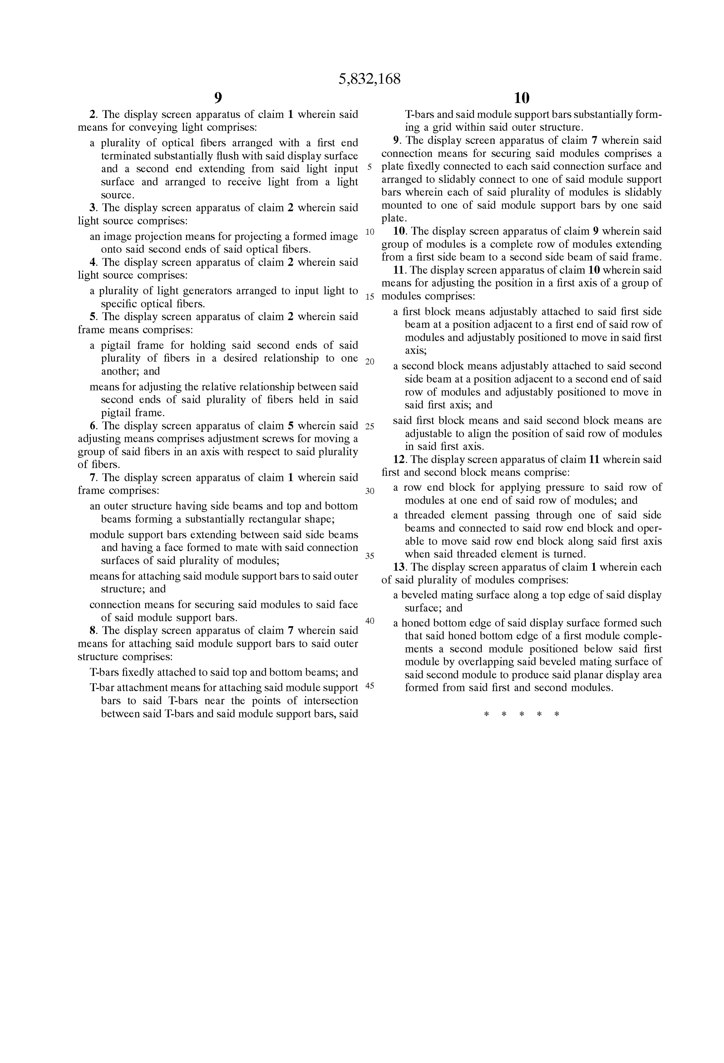
2. The display Screen apparatus of claim 1 wherein Said T-bars and Said module Support bars Substantially form means for conveying light comprises: ing a grid within Said outer Structure. a plurality of optical fibers arranged with a first end 9. The display screen apparatus of claim 7 wherein said terminated Substantially flush with Said display Surface connection means for Securing Said modules comprises a and a Second end extending from Said light input plate fixedly connected to each Said connection Surface and Surface and arranged to receive light from a light arranged to Slidably connect to one of Said module Support SOCC. bars wherein each of said plurality of modules is slidably 3. The display Screen apparatus of claim 2 wherein Said mounted to one of Said module Support bars by one Said light Source comprises: plate.
an image projection means for projecting a formed image 10. The display screen apparatus of claim 9 wherein said onto Said Second ends of Said optical fibers. group of modules is a complete row of modules extending 4. The display Screen apparatus of claim 2 wherein Said from a first Side beam to a Second Side beam of Said frame. 11. The display screen apparatus of claim 10 wherein said light Source comprises:
a plurality of light generators arranged to input light to 15 means modules for adjusting the position in a first axis of a group of comprises:
Specific optical fibers.
5. The display Screen apparatus of claim 2 wherein Said a first block means adjustably attached to Said first Side frame means comprises: beam at a position adjacent to a first end of Said row of modules and adjustably positioned to move in Said first a pigtail frame for holding Said Second ends of Said axis, plurality of fibers in a desired relationship to one another, and a Second block means adjustably attached to Said Second means for adjusting the relative relationship between Said Side beam at a position adjacent to a Second end of Said row of modules and adjustably positioned to move in second ends of said plurality of fibers held in said Said first axis, and pigtail frame. Said first block means and Said Second block means are 6. The display Screen apparatus of claim 5 wherein Said 25 adjustable to align the position of Said row of modules adjusting means comprises adjustment Screws for moving a in Said first axis.
group of Said fibers in an axis with respect to Said plurality of fibers. 12. The display Screen apparatus of claim 11 wherein Said 7. The display Screen apparatus of claim 1 wherein Said first and Second block means comprise:
frame comprises: a row end block for applying pressure to Said row of an Outer Structure having Side beams and top and bottom modules at one end of Said row of modules, and beams forming a Substantially rectangular shape; a threaded element passing through one of Said Side module Support bars extending between said Side beams beams and connected to said row end block and oper and having a face formed to mate with Said connection 35 able to move Said row end block along Said first axis when said threaded element is turned.
Surfaces of Said plurality of modules, 13. The display Screen apparatus of claim 1 wherein each means for attaching Said module Support bars to Said outer of Said plurality of modules comprises: Structure; and a beveled mating Surface along a top edge of Said display connection means for Securing Said modules to Said face Surface; and
a honed bottom edge of Said display Surface formed Such 8. The display screen apparatus of claim 7 wherein said that Said honed bottom edge of a first module comple means for attaching Said module Support bars to Said outer ments a Second module positioned below Said first Structure comprises: module by overlapping Said beveled mating Surface of T-bars fixedly attached to said top and bottom beams; and Said Second module to produce Said planar display area T-bar attachment means for attaching Said module Support 45 formed from Said first and Second modules. bars to Said T-bars near the points of interSection between Said T-bars and Said module Support bars, Said
Provenance
- Collection
- Cited prior art
- Original PDF
- patentimages.storage.googleapis.com →
- Filed
- 1997-07-08
- Pages
- 15
- Method
- pdftotext (the PDF's own text layer) + pdftoppm 300dpi page scans
- Source
- Google Patents bibliographic record
- Granted
- 1998-11-03
- Inventors
- Rex A. Yenter; Advance Display Technologies Inc
- Transcribed from
- patentimages.storage.googleapis.com →