patent · US5799126
Light guide device, light source device, and liquid crystal display device
25 August 1998
Page 1 — bibliographic record
United States Patent (19) 11 Patent Number: 5,799,126 Nagatani et al. 45 Date of Patent: Aug. 25, 1998 54 LIGHT GUIDE DEVICE, LIGHT SOURCE 3,901,581 8/1975 Thiel ......................................... 385/43 DEVICE, AND LIQUID CRYSTAL DISPLAY 4,240,692 12/1980 Winston .................................. 38.5/146 DEVICE 4,382,656 5/1983 Gilby ..................................... 38.5/146 4,915,479 4/1990 Clarke ....................................... 362/32 75 Inventors: Shinpei Nagatani; Fumiaki Yamada; 4,978,186 12/1990 Mori ................. ... 385/90 Motohiko Fukuhara, all of Kawasaki, 5,093,890 3/1992 Bregman et al. ... ... 38.5/146 Japan 5,359,691 10/1994 Tai et al. .............. ... 38.5/146 5,462,700 10/1995 Beeson et al. ... ... 38.5/46 (73) Assignee: Fujitsu Limited, Kawasaki, Japan 5,475,571 12/1995 Dassanayake ........................... 385/901
FOREIGN PATENT DOCUMENTS
54-24646 2/1979 Japan ...... use 385/43 22 Filed: Apr. 21, 1995 63-75704 4/1988 Japan ....................................... 385/43 Related U.S. Application Data
Primary Examiner-John Ngo 62 Division of Ser. No. 265,678, Jun. 24, 1994. Attorney; Agent, or Firm-Greer, Burns, & Crain. Ltd. 30 Foreign Application Priority Data 57 ABSTRACT Aug. 3, 1993 JPl Japan .................................... 5-192585 An object of the present invention is to provide a light guide (51) Int. Cl. ... G02B 6/00 device which can emit light rays of high directivity with high 52) U.S. C. .......................... 385/146; 385/901; 38.5/115; efficiency irrespective of incident angles, and a light source 385/43 device using the light guide device which can provide light 58 Field of Search .............................. 3.85/15-121, 43. rays of high directivity with high efficiency irrespective of 385/146,901 emitting characteristics of light source lamps, and a liquid crystal display device which is small-sized and can display 56 References Cited at very high luminance and is free from color tone changes
depending on visual angles over a wide field angle.
2589,569 3/1952 Peter et al. ............................. 385/901 54 Claims, 27 Drawing Sheets
Page 2
Drawing sheet — no readable text.
Page 3
Drawing sheet — no readable text.
Page 4
Drawing sheet — no readable text.
Page 5
Drawing sheet — no readable text.
Page 6
Drawing sheet — no readable text.
Page 7
Drawing sheet — no readable text.
Page 8
Drawing sheet — no readable text.
Page 9
Drawing sheet — no readable text.
Page 10
Drawing sheet — no readable text.
Page 11
Drawing sheet — no readable text.
Page 12
Drawing sheet — no readable text.
Page 13
Drawing sheet — no readable text.
Page 14
Drawing sheet — no readable text.
Page 15
Drawing sheet — no readable text.
Page 16
Drawing sheet — no readable text.
Page 17
Drawing sheet — no readable text.
Page 18
Drawing sheet — no readable text.
Page 19
Drawing sheet — no readable text.
Page 20
Drawing sheet — no readable text.
Page 21
Drawing sheet — no readable text.
Page 22
Drawing sheet — no readable text.
Page 23
Drawing sheet — no readable text.
Page 24
Drawing sheet — no readable text.
Page 25
Drawing sheet — no readable text.
Page 26
Drawing sheet — no readable text.
Page 27
Drawing sheet — no readable text.
Page 28
Drawing sheet — no readable text.
Page 29
LIGHT GUIDE DEVICE, LIGHT SOURCE cooling periods of time to light again after the light sources DEVICE, AND LIQUD CRYSTAL DISPLAY are lit. This is also a problem.
DEVICE Light rays which are not considered in designs are reduced to useless light rays because such light source,
This is a division, of application Ser. No. 08/265,678, 5 which are called substantial point light sources, are actually filed Jun. 24, 1994, pending. provided by finite light sources, which lower efficiency. This is also a problem.
BACKGROUND OF THE INVENTION
SUMMARY OF THE INVENTION
The present invention relates to a light guide device, especially a light guide device for providing light rays of 10 A first object of the present invention is to provide a light high directivity, and a light source device which can realize guide device for efficiently emitting light rays of high source light of very high directivity by the use of the light directivity irrespective of incident angles of incident light, guide device. and a liquid crystal display device which can and a method for fabricating the light guide device. be small-sized and can display at very high luminance and 15 A second object of the present invention is to provide a can be free from color tone changes depending on visual light source device which is small in size and can provide angles over a wide field angle. light rays of high directivity by the light guide device Generally light source devices used in spot lights and intrespective of emitting characteristics of a light source image forming optical systems demand high directivity. lamp.
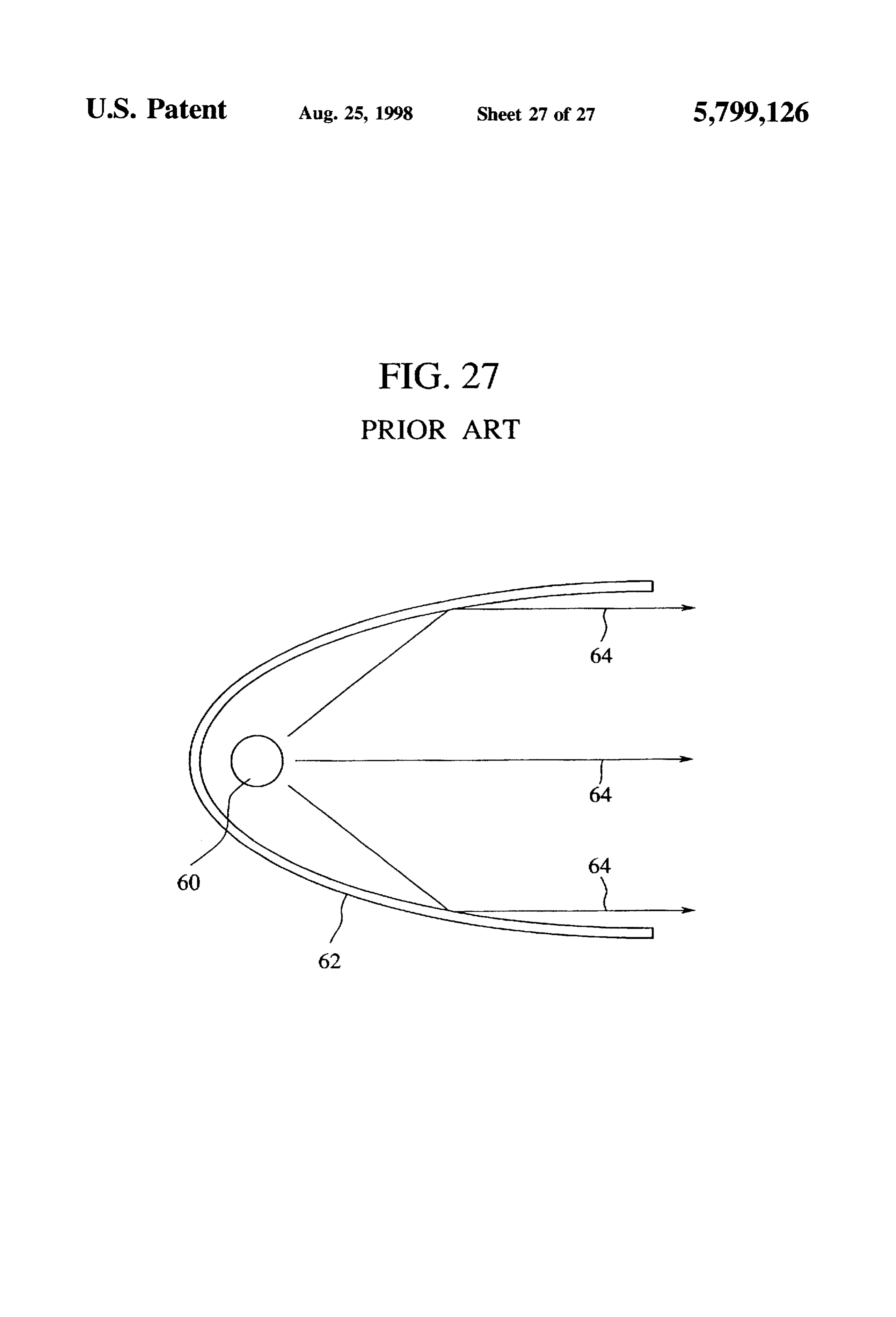
Light rays of very high directivity which are especially A third object of the present invention is to provide a called parallel rays is demanded in image forming optical liquid crystal display device which is small in size and can systems for magnifying light which has passed through, e.g., display at very high luminance and is free from color tone panels of liquid crystal display devices and projecting the changes depending on visual angles over a wide field angle. Sa O. SCTCCS. The first object is achieved by a light guide device A conventional optical device for use mainly in projection 25 comprising a pole-shaped transparent body having an inci optical systems will be explained with reference to a sche dent end surface on which light is incident having a smaller matic sectional views of FIG. 27. area, and a exit end surface at which the light exit in light As a light source 60, e.g., halogen lamp or a metal halide rays having a larger area.
lamp is used. A reflecting mirror 62 is disposed around the In the above-described light guide device it is preferred outer circumference of the light source 60. The reflecting 30 that, an area of the exit end surface is 3 times or more than mirror 62 has suitable set surface angles at respective that of the incident end surface.
positions so that source light from the light source 60 has In the above-described light guide device, the pole-shaped reflected as substantially parallel rays. That is, the reflecting transparent body is cylindrical and polygonal near at least mirror 62 is generally shaped as aparabola and has reflection one of the incident end surface and the exit end surface. angles set so that the source light is reflected as light rays of 35 In the above-described light guide device, a coating layer a set directivity, is provided on an outer circumferential portion of the Accordingly the source light from the light source 60 is transparent pole-shaped body and having a hardness below reflected by the reflecting mirror 62 to be exiting light rays the transparent pole-shaped body, 64 of high directivity in the form of substantially parallel The above-described light guide device further comprises rays. an assistant member in a form of prism disposed on the exit Conventional light source devices used in spotlights for end surface of the light guide device, for correcting a general lighting, and in image forming optical systems use direction of the exit light ray.
light sources whose light emitting forms, such as filaments, A light guide device may comprise a line of the above are substantially point light sources, and condense their 45 described light guide devices arranged in parallel with each source light by reflecting mirrors so as to improve directiv other, and formed integral; a first connection disposed on ity. one end of the line of the light guide devices, and having a However, to condense light by the reflecting mirrors in partial shape of the light guide devices; and a second such conventional light source devices, it is necessary to connection disposed on the other end of the line of the light position the reflecting mirrors at a distance from the light 50 guide devices, having a partial shape of the light guide sources in order to allow the light sources, which are devices which is different from that of the first connection, actually light emitting points at finite distances from the the second connection making up together with the first reflecting mirrors, to be accepted as point light sources. The connection substantially the same shape as the light guide reflecting mirrors must be large-sized, and it is difficult to device.
reduce the size of the light source devices themselves. This 55 The above-described light guide device comprises a light is a problem. guide unit including light guide devices arranged in rows or To meet the condition that light sources which are sub in plane, and a resin layer formed on the exit end surface of stantially point light sources, halogen lamps, metal halide the arranged light guide devices in one piece therewith, and lamps, etc., which are generally highly efficient and bright, having substantially the same refractive index and light are used as substantially point light sources. The light source transmittance as the light guide device. represented by such metal halide lamps, etc. have short life In the above-described light guide device it is preferred times. This is their disadvantage. Conversely, light sources, that, a refractive index ratio between the resin layer and the such as fluorescent tubes, which have long life times and light guide devices is above about 0.97.
high efficiency, cannot be used because they are diffused The first object is achieved by a method for fabricating the light sources. This is also a problem. 65 above-described Eight guide device comprising the steps of The substantial point light sources, such as metal halide arranging a plurality of the light guide devices in plane. lamps, etc. do not instantaneously light and take long applying a UV solidifying resin having substantially the
Page 30
same refractive index and light transmittance as the light or a matrix, and reflected light from the reflecting mirror is guide devices onto the exit end surface defined by the plural substantially parallel light rays.
light guide devices, and solidifying the UV solidifying resin In the above-described light source device the opening is by UV radiation to form the resin layer formed integral with a stripe or a plurality of pinholes linearly arranged along the the plural light guide devices. linear light source, the fiber light guide member is a plurality In the above-described method for fabricating a light of bundles of fiber light guide members for optically cou guide device, when the UV solidifying resin is solidified, pling the opening in the shape of a stripe or a plurality of UV radiation is applied with a specular plate placed on the pinholes with the incident end surfaces of the plural light surface of the UV solidifying resin. guide devices arranged in a matrix, and the plural fiber light The first object is achieved by a method for fabricating the 10 guide members are adjusted in terms of length and flexure so above-described light guide device comprising the steps of that the exit end surfaces of the light guide devices are arranging a plurality of the light guide devices in plane, arranged in a line or a matrix on the same level. placing the exit end surface of the arranged light guide In the above-described light source device the opening is devices in a vessel holding a polymerization adhesive hav 15 a stripe or a plurality of pinholes, the pole-shaped light guide ing substantially the same refractive index and light trans member is a plurality of bundles of pole-shaped light guide mittance as the light guide devices, and polymerization members for optically coupling the opening in the shape of adhering, in this state, the resin to the light guide devices, the stripe or the plural pinholes with the incident end whereby the resin layer is formed integral with the plural surfaces of the plural light guide devices arranged in a light guide devices. 20 matrix, circular pole-shaped or rectangular pole-shaped
In the above-described method, the vessel has the interior transparent assistant members of set lengths are disposed surface formed in a speculum. between the slant reflecting surfaces of the pole-shaped light The second object is achieved by a light source device guide members or the end surfaces of the prisms with the comprising a light source, a reflection box containing the slant reflecting surfaces, and the incident end surfaces of the light source and having the inside wall coated with a 25 light guide, or on the forward ends of the assistant members reflecting surface, an opening formed in a side of the of the light guide devices, and the assistant light guide reflection box, and the above-described light guide device members are adjusted in terms of length so that the exit end disposed with the incident end surface opposed to the light surfaces of the light guide devices are arranged in a line or SOCC a matrix on the same level.
In the above-described light source device there is dis In the above-described light source device the light source posed a light guide member for optically coupling the is a plurality of parallel linear light sources, the opening is opening and the incident end surface of the light guide a plurality of pinholes arranged in a matrix, and a plurality device. of the light guide devices are arranged in a matrix corre In the above-described light source device, the light guide sponding to the matrix of the pinhole.
member is a flexible fiber light guide member. 35 In the above-described light source device the exit end In the above-described light source device the light guide surfaces of the arranged light guide devices are on the same member is a pole-shaped member having a slant reflecting level.
surface on the end surface contacting the incident end The third object is achieved by a liquid crystal display surface of the light guide device. device comprising the light source device, and a liquid In the above-described light source device the light source crystal panel disposed on the exit surface of the light source device is a substantial point light source, the opening is at device.
least one pinhole, and the light guide device is disposed in The above-described liquid crystal display device further the pinhole. comprises a light diffusing sheet for diffusing light beams of In the above-described light source device the light source directivity disposed on the liquid crystal panel. is a substantial point light source, the opening is a slit, a 45 According to the present invention, the light guide device plurality of the light guide devices are anranged linearly is a pole-shaped transparent body, and has a smaller-area end along the slit, and the light guide devices arranged linearly surface as the incident end surface and a larger-area end along the slit are arranged in at least one line. surface as the exit end surface, whereby light incident on the In the above-described light source device, the light 50 incident end surface reaches the boundary surface of the Source is a linear light source, the opening is a plurality of light guide device to reflect in accordance with the law of pinholes arranged in a line or a matrix along the linear light total reflection, and reaches the opposed boundary surface to source, and a plurality of the light guide devices are arranged reflect thereon. The light repeatedly thus reflects and gradu in a line or a matrix along the arrangement of the pinholes. ally changes into light rays vertical to the exit end surface In the above-described light source device the light source 55 and exits in the light rays at the exit end surface. Thus even is a linear light source, the opening is a slit, and a plurality when the incident light is diffused light. exit light rays of of the slits are disposed along the linear light source, a high directivity are available with high efficiency. plurality of the light guide devices are disposed along the The cylindrical transparent light guide device is used, and slit, and a plurality of lines of the light guide devices are light is incident on the smaller-area incident end surface, disposed along the arrangement of the slit, and exit end whereby even the incident light is diffused light, highly surfaces of the light guide devices are arranged in a line or directive light rays can exit at the exit end surface with high a matrix. efficiency.
In the above-described light source device, the plurality of The exterior surface of the light guide devices are coated the light guide devices are arranged in a fan-shape. with the coating layer of a lower hardness, and the light In the above-described light source device there is pro 65 source device can have little luminance disuniformity. vided a reflecting mirror for reflecting light exiting from the A plurality of the light guide devices are interconnected to exit end surfaces of the light guide devices arranged in a line each other in a line of the light guide devices. Accordingly
Page 31
non-light emitting parts are absent, and groups of the light pole-shaped assistant members on the forward ends of the guide devices having a uniform luminance on the surface exit end surfaces are adjusted so that the members are on the can be formed. same level, whereby the plural exit end surfaces arranged in The acrylic resin layer having substantially the same a matrix define a single plane exit surface.
refractive index as the light guide devices is provided A number of light guide devices are disposed in a matrix integral with the light guide devices on the exit surface in a number of pinhole-shaped openings formed in the defined by the light guide devices. Accordingly the light surface of the reflection box containing the parallel plural guide device can have little disuniformity of a luminance linear light sources, whereby the plural exit end surfaces and good directivity. arranged in a matrix define the single plane exit surface In the light source device using the above-described light 10 without the use of light guide members. guide device, i.e. the light guide device is disposed in the The liquid crystal display device has the small-sized light opening in a surface of the reflection box containing the light source device which can emit highly directive light beams at source with the incident end surface opposed to the light high efficiency, whereby the liquid crystal display device can source, whereby light rays of high directivity can exit at the be small in size and can display at very high luminance of exit end surface of the light guide device with high efficiency 5 above ten thousands cd/m. Such liquid crystal display irrespective of emitting characteristics of the light source, device is applicable to outdoor display boards, display i.e., whether the light source is a point light source or a boards which have to be looked from a distance, etc. diffused light source. The light diffusing sheet 92 is provided on the liquid The optical fiber as a light guide component which 20 crystal panel 86, whereby directive beams which have exited optically couples the incident end surface of the light guide the light guide devices 10 and passed through the liquid device with the substantial point light source, and a length crystal panel are diffused, whereby the liquid crystal display and flexure of which are adjustable is disposed, whereby device can be free from color tone changes depending on light rays of high directivity can be emitted with high visual angles over a wide field angle.
efficiency in a prescribed direction at a prescribed position 25 As a result, in the light source device for use in image distant from the substantial point light source. forming optical systems, such as liquid crystal display The rectangular pole-shaped light guide member as a light devices, which requires light rays of high directivity with guide component which optically couples the incident end high efficiency, the light source is not limited to halogen surface of the light guide device with the substantial point lamps, metal halide lamps or others. and diffusing light light source, and a length of which are adjustable is sources of long lifetimes, such as fluorescent lamps, can be disposed, whereby light rays of high directivity can be 30 used. In the light source device using conventional a sub emitted with high efficiency in a prescribed direction at a stantial point light sources, improved directivity and lower prescribed position distant from the substantial point light electric power consumption can be achieved. Since the light
SOCC.
guide device itself is small, the light source device can be
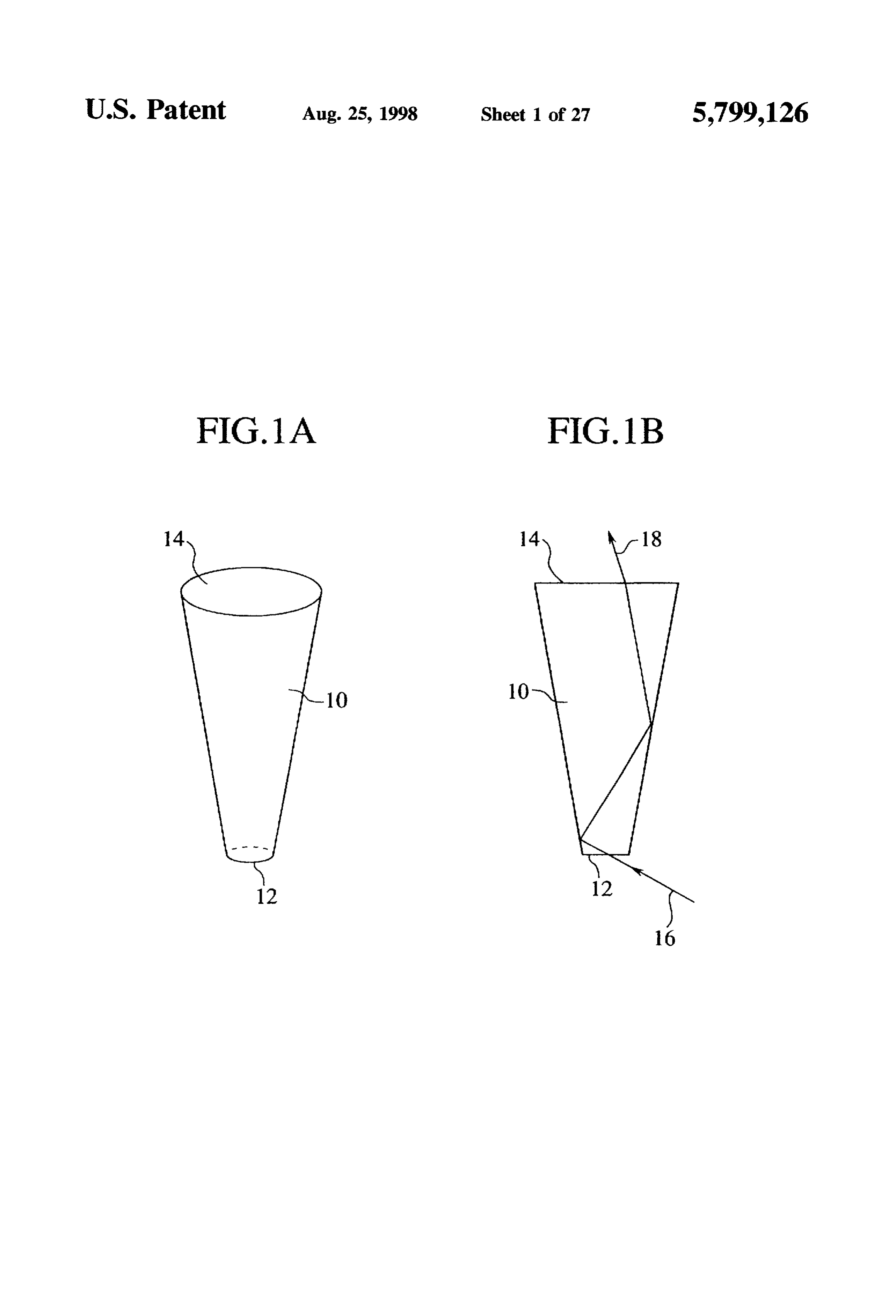
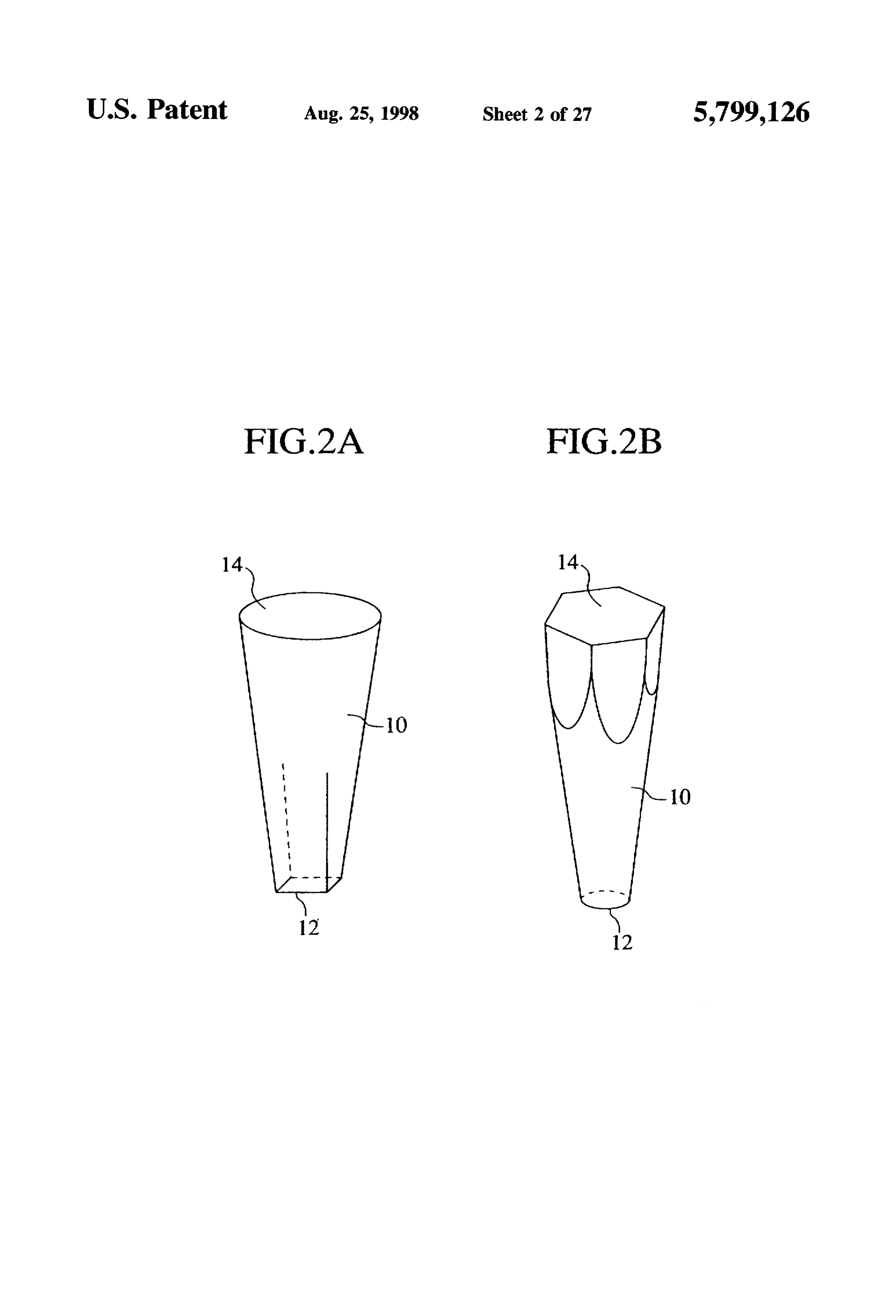
A substantial point light source, and the incident end 35 small in size. Furthermore, the liquid crystal display device surfaces of a plurality of the light guide devices are optically containing the light source device can also be small in size. coupled to each other through the opening in the form of a slit or pinhole-shaped, whereby a plurality of light rays of BRIEF DESCRIPTION OF THE DRAWINGS high directivity can exit with high efficiency. FIGS. 1A and 1B are a perspective view and a schematic The incident end surfaces of a plurality of light guide sectional view of the light guide device according to a first devices and the substantial point light source are optically embodiment of the present invention, coupled to each other through the opening in the form of a slit, and the reflecting mirror is provided for reflecting the theFIGS. 2A and 2B are perspective views of variations of light guide device of FIG. 1A.
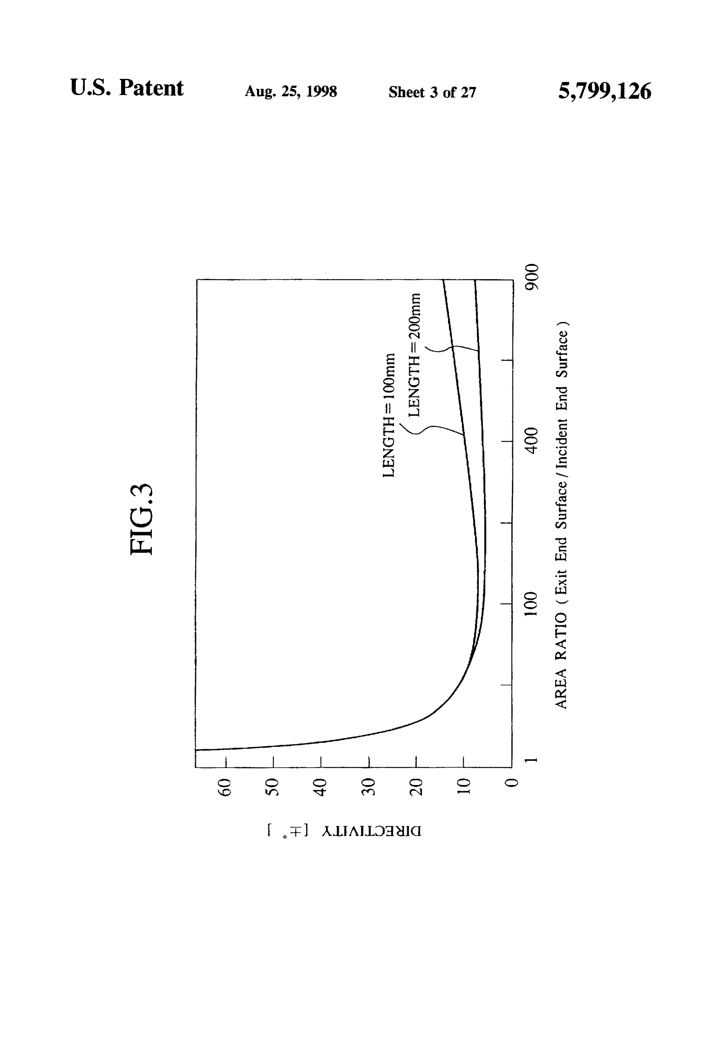
exit light rays from the exit end surfaces, whereby substan FIG. 3 is characteristic curves of relationships between tial parallel rays of high directivity can be emitted with high 45 shapes efficiency. The presence of the reflecting mirror allows the the exitoflight the light guide device of FIG. 1 and directivity of rays.
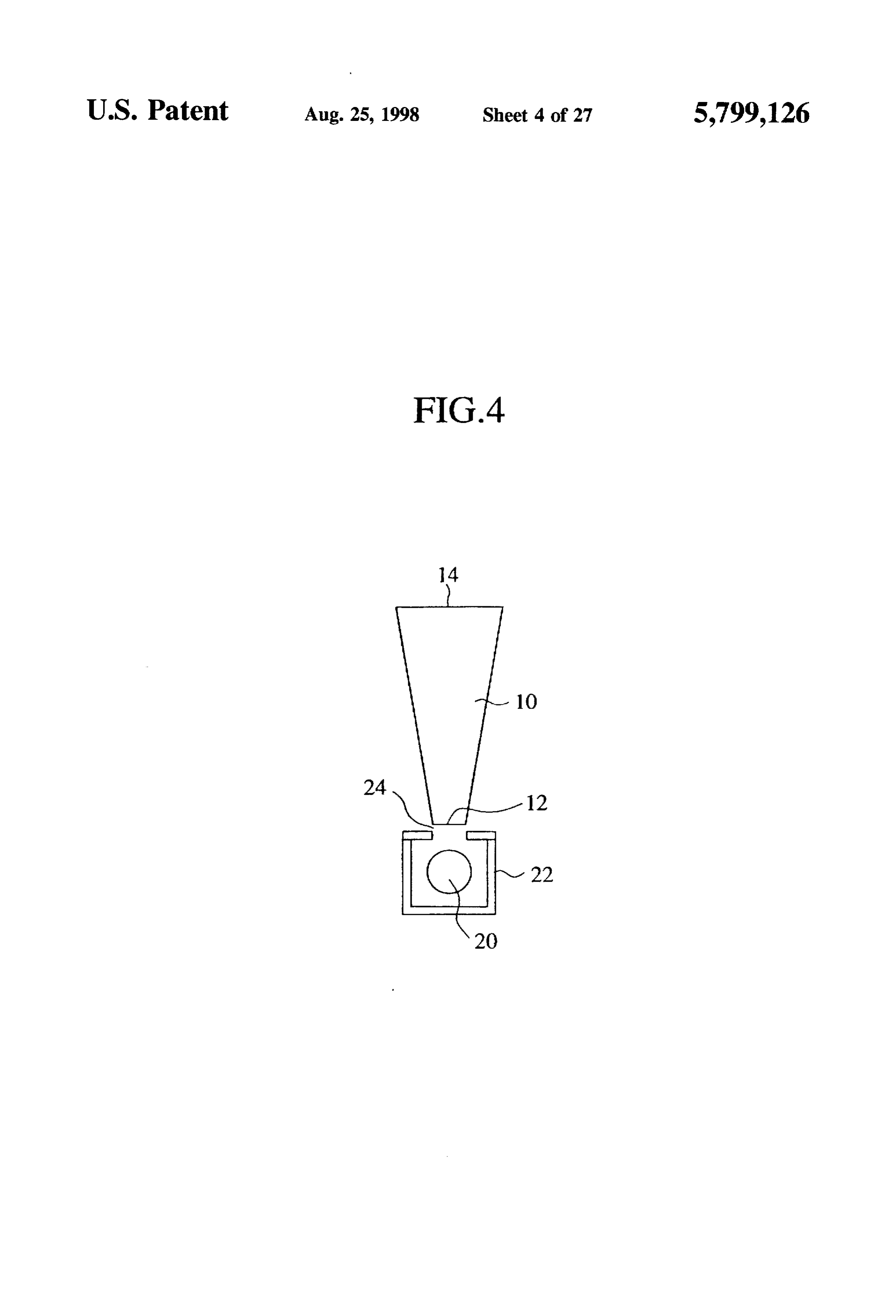
light source device itself to be small in size because the light FIG. 4 is a schematic sectional view of the light source guide device is sufficiently small.
device according to a second embodiment of the present
The linear light source is used as the light source, and the invention.
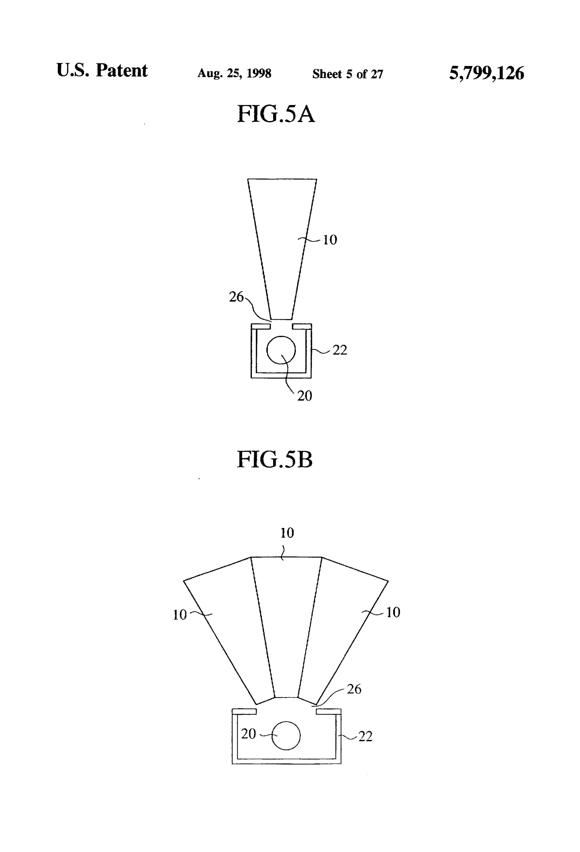
incident end surfaces of the plural light guide devices and 50 FIGS. 5A and 5B are schematic sectional views of the the linear light source are optically coupled with each other through the plural pinhole-shaped openings formed along light source device according to a third embodiment of the the linear light source, whereby light rays of high directivity present invention.
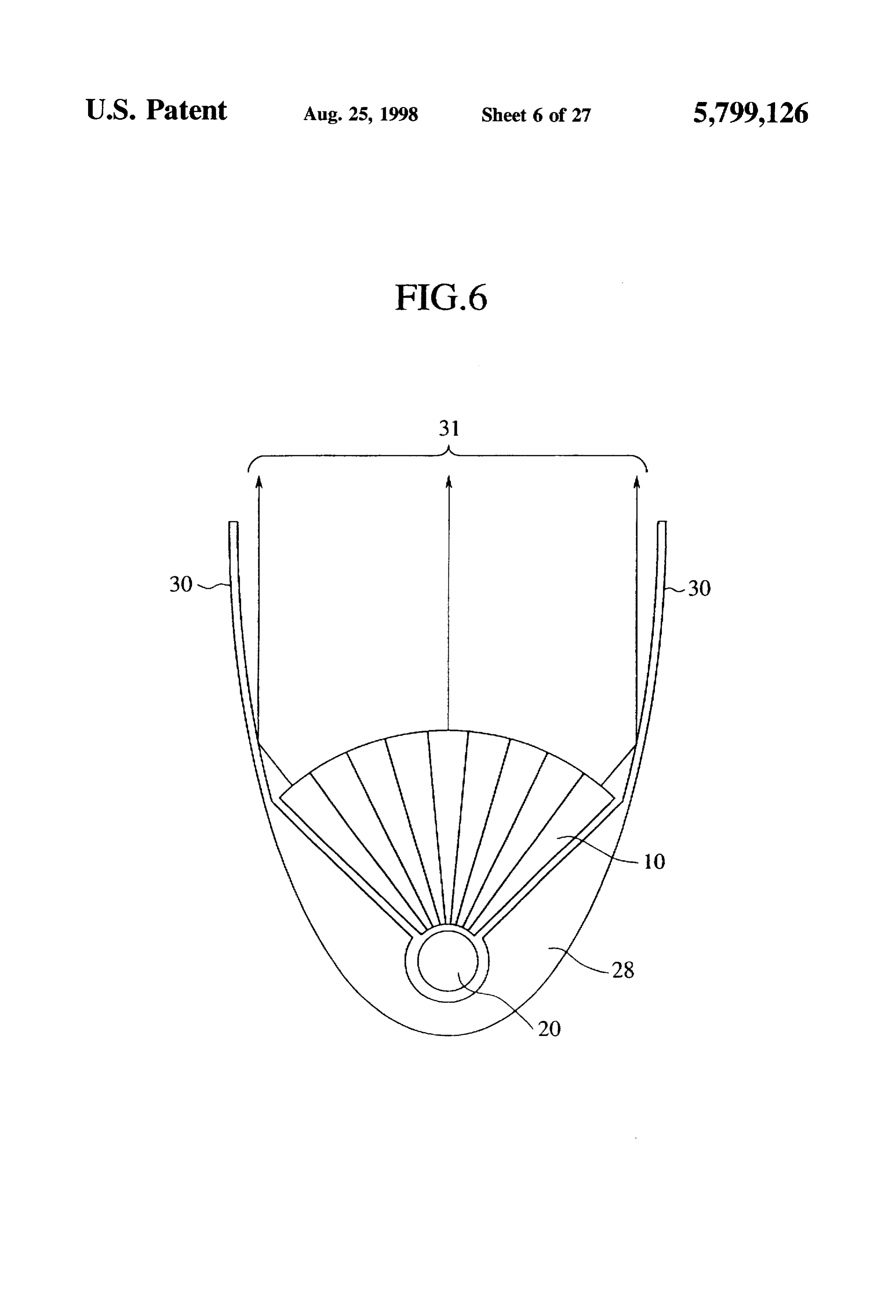
can be emitted with high efficiency from the plural end FIG. 6 is a schematic sectional view of the light source surfaces arranged linearly on a set level. 55 device according to a fourth embodiment of the present The stripe-shaped opening with a large opening area is invention.
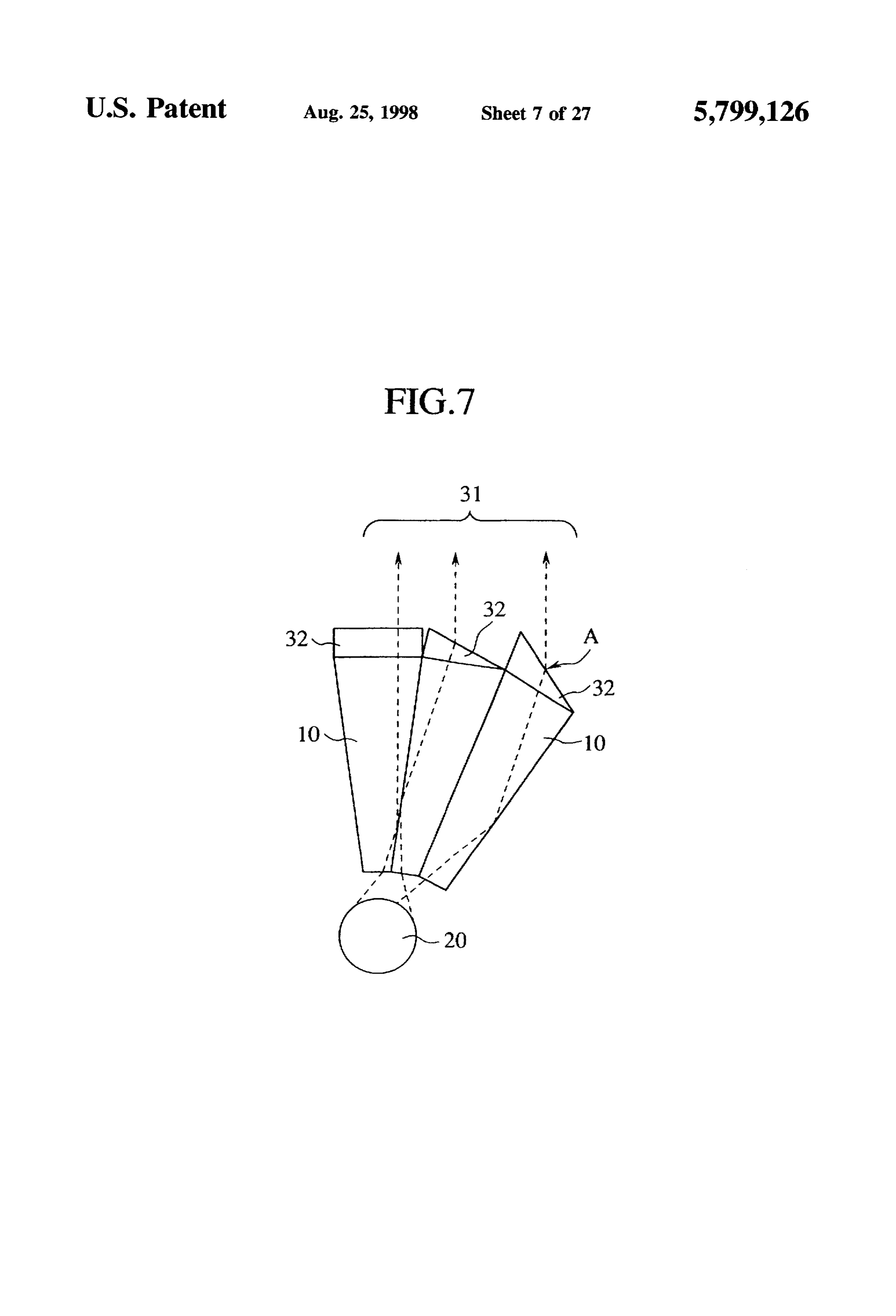
used, whereby light rays of directivity can be more effi FIG. 7 is a schematic sectional view of a variation of the ciently emitted from the exit end surfaces and can have light source device of FIG. 6.
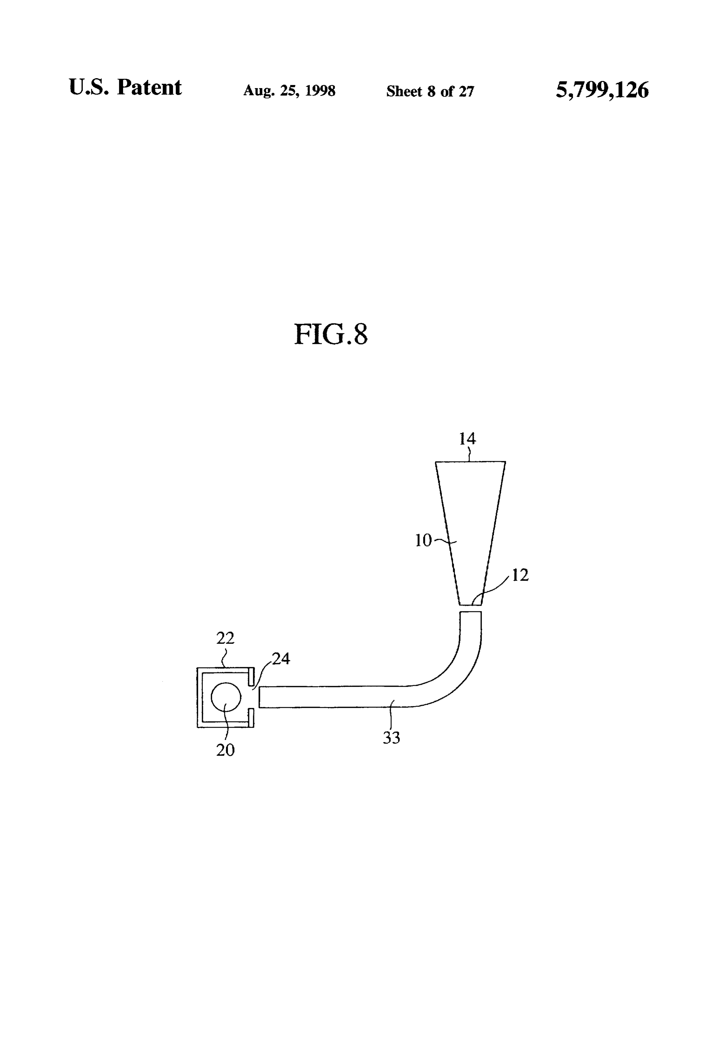
higher luminance, while the respective optical fibers opti FIG. 8 is a schematic sectional view of the light source cally coupling the linear light source and the plural light device according to a fifth embodiment of the present guide devices are adjusted in terms of elongation and invention.
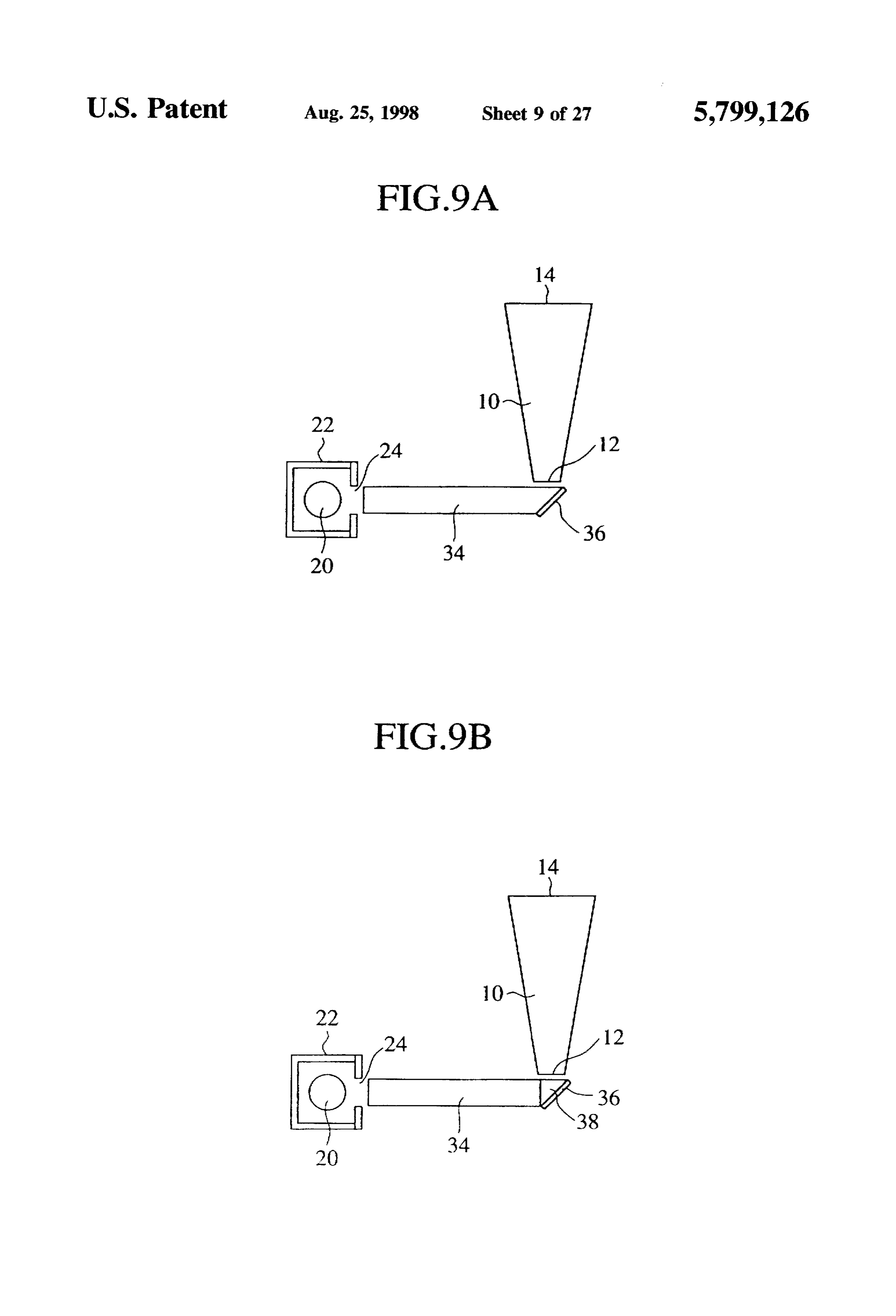
flexure, whereby the plural exit end surfaces arranged in a FIGS. 9A and 9B are schematic sectional views of the matrix can define a single plane exit surface. light source device according to the sixth embodiment of the The stripe-shaped opening is used, the linear light source present invention.
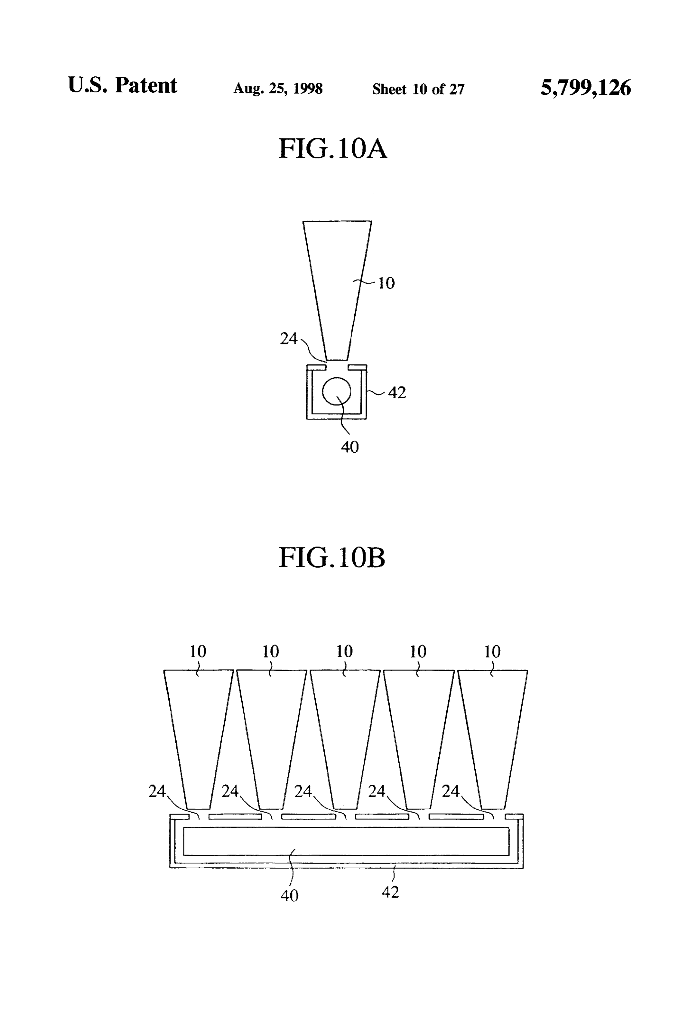
and the incident end surfaces of the plural light guide 65 FIGS. 10A and 10B are schematic sectional views of the devices are optically coupled with each other by the rect light source device according to a seventh embodiment of angular pole light guide members, while lengths of the the present invention.
Page 32
FIG. 11 is schematic sectional view of the light source As shown in FIG. 1B, when diffused light 16 from a set device according to an eighth embodiment of the present light source enters the light guide device 10 at an arbitrary invention. angle at the incident end surface 12 thereof, the light which FIG. 12 is a schematic sectional view of the light source has entered the light guide device 10 arrives at the boundary device according to a ninth embodiment of the present surface thereof.
invention. Because the light guide device 10 is a cylindrical trans FIGS. 13A to 13D are views of a rectangular pole-shaped parent body of acrylic resin, the light enters the light guide light guide member of the light guide device of FIG. 12, and device 10 is condensed within a critical angle of the trans of its variations. parent body to be totally reflected in accordance with Snell's
FIG. 14 is a schematic sectional view of the light source law determined by a refractive index ratio between the light device according to a tenth embodiment of the present guide device 10 and an outer circumferential space. The totally reflected light arrives at the opposed boundary sur invention.
FIG. 15 is a perspective view of the light source device face to be again reflected in accordance with the law of total reflection.
according to an eleventh embodiment of the present inven 15 Because the light guide body 10 is gradually diverged tion.
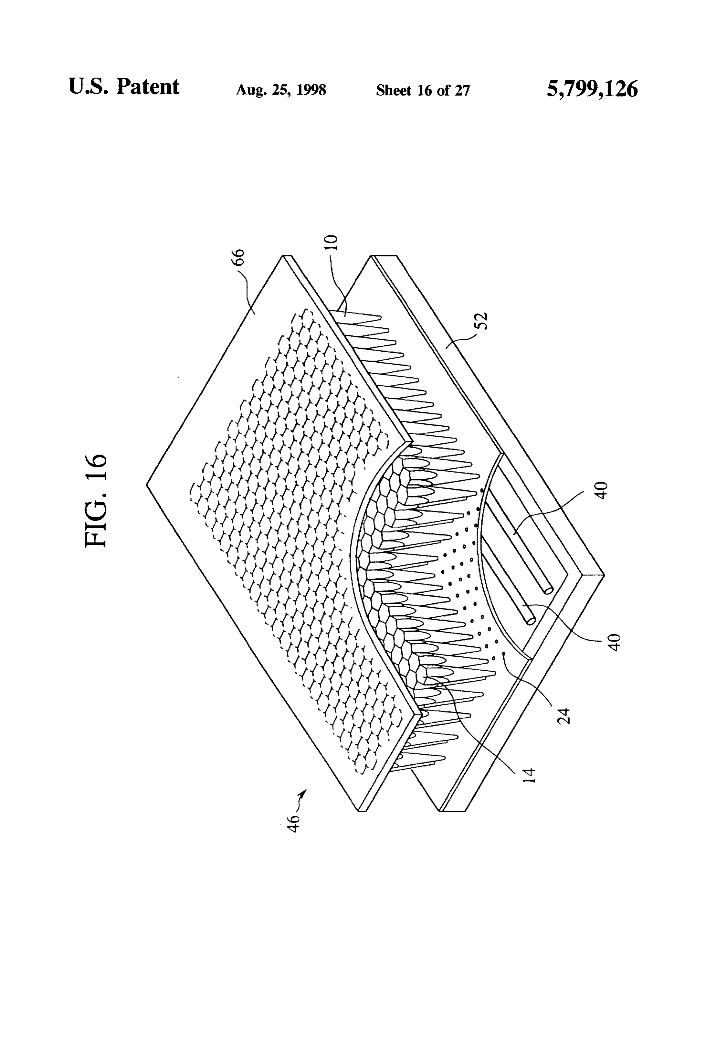
FIG. 16 is a perspective view of the light source device from the incident end surface 12 toward the exit end surface according to a twelfth embodiment of the present invention. graduallyreflection 14, this is repeated, whereby the reflected light
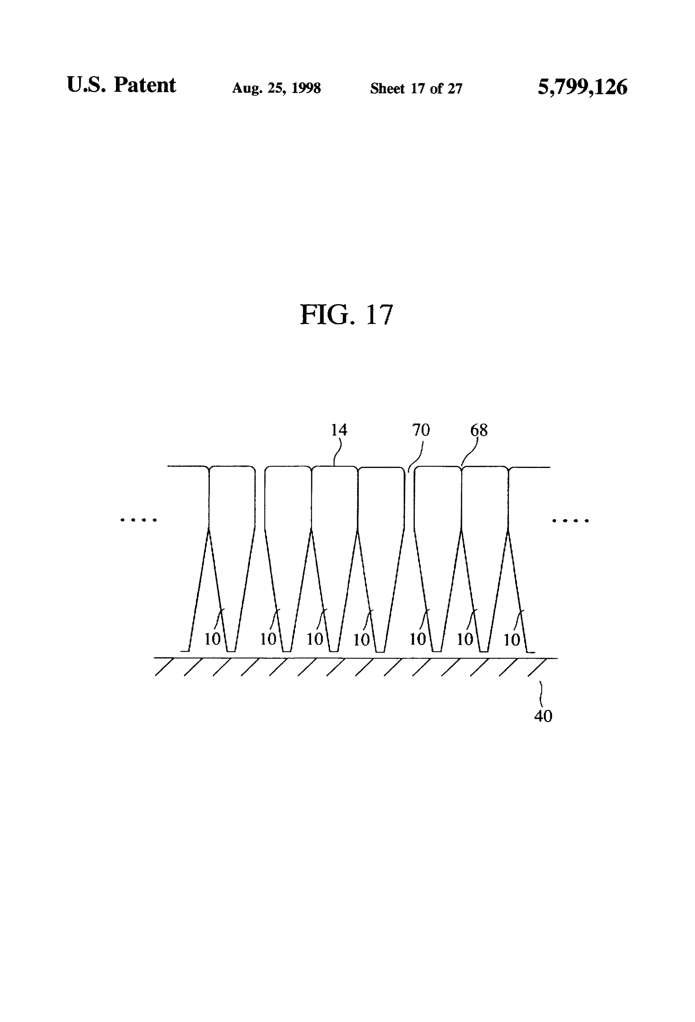
FIG. 17 is a partially enlarged sectional view of the light surface 12 or the exit light changes into end rays vertical to the incident end surface 14. Thus finally highly source device according to the eleventh embodiment of the directive light rays 18 of an about 10°
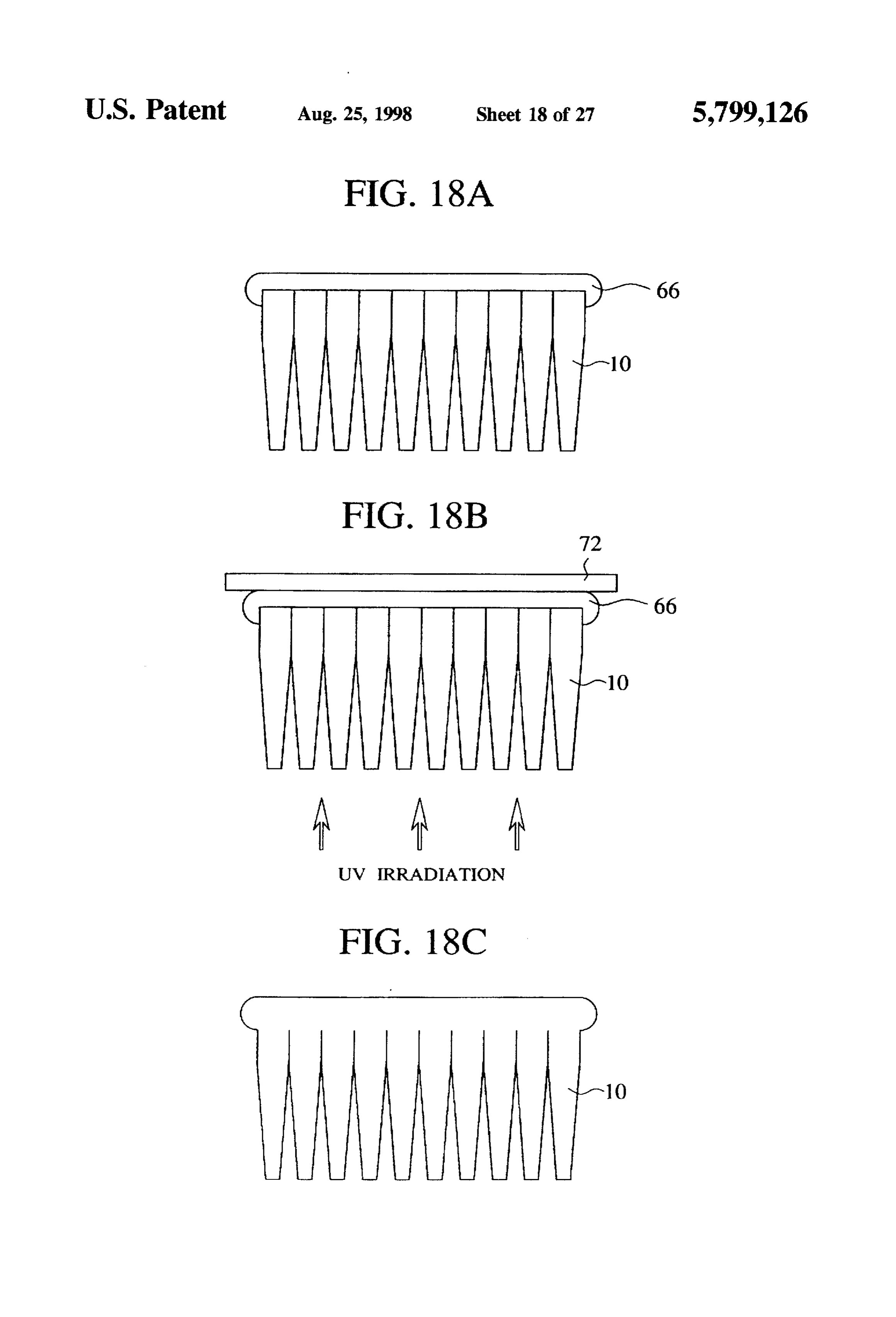
directivity exit at the present invention. exit end surface 14. Since the light which has entered the FIGS. 18A to 18C are views (part 1) explanatory of the light guide device 10 repeats only total reflection, most of method for fabricating the light source device according to the incident light becomes exit light rays with high effi the twelfth embodiment of the present invention. ciency.
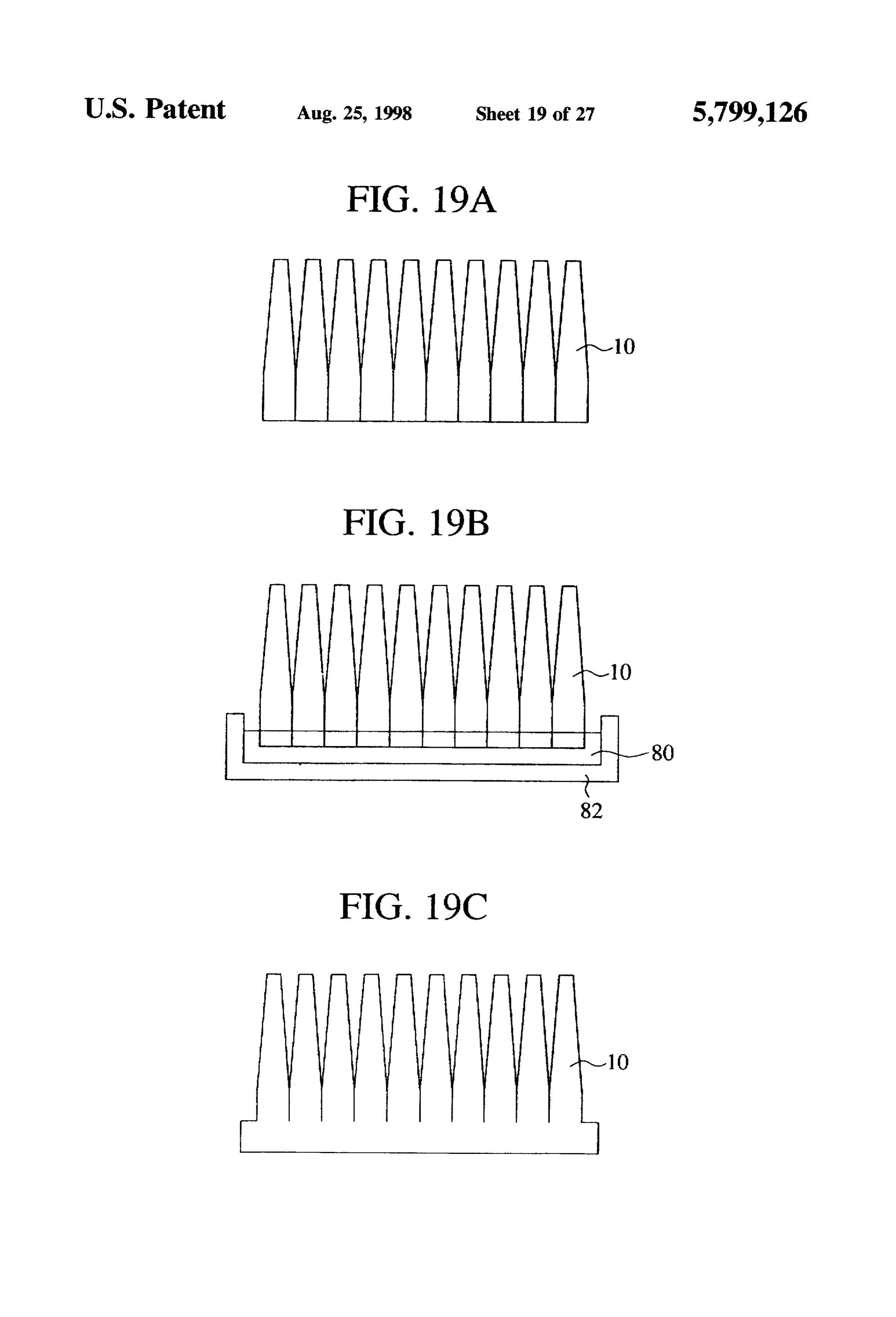
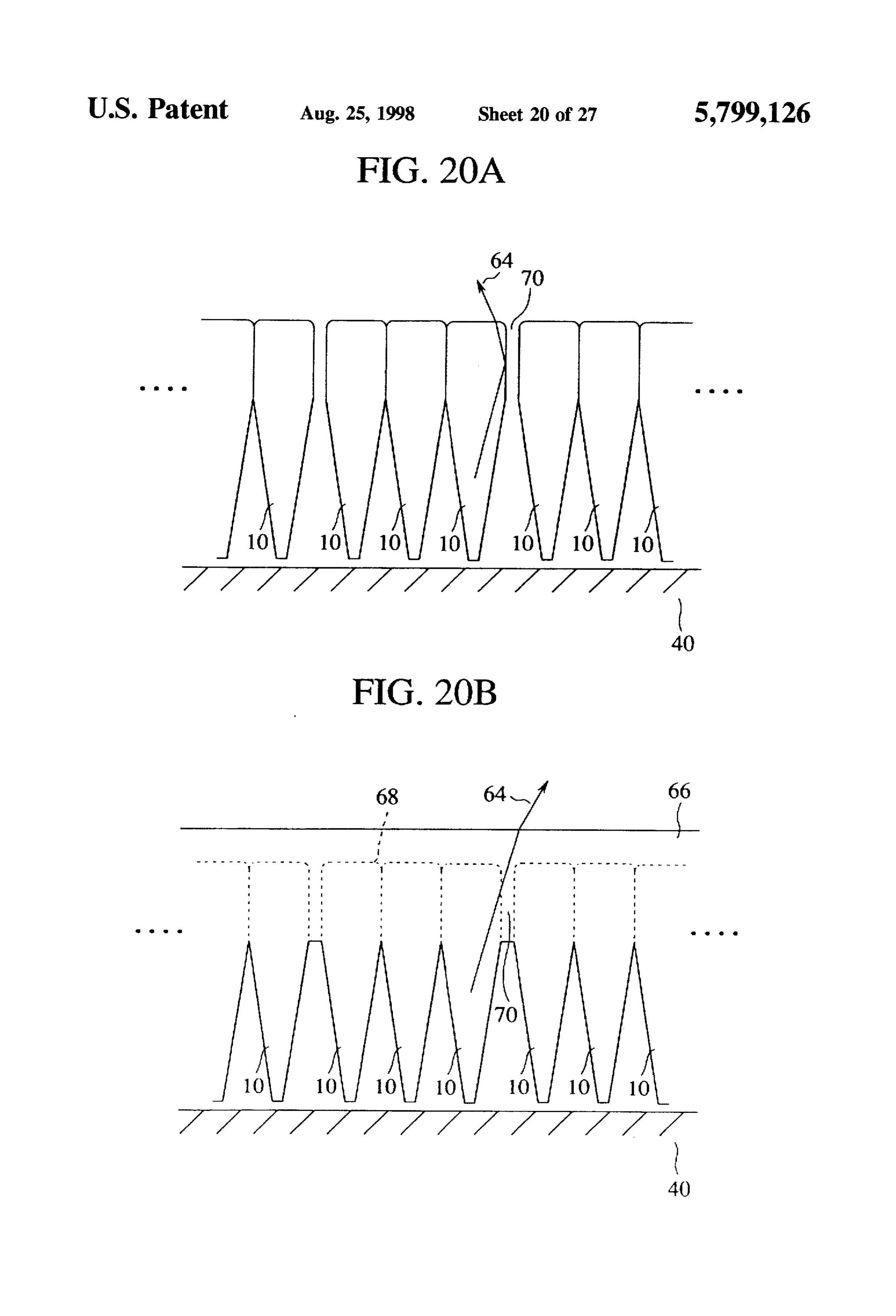
FIGS. 19A to 19C are views (part 2) explanatory of the 25 Thus, according to the first embodiment, the cylindrical method for fabricating the light source device according to transparent light guide device 10 is used, and light is the twelfth embodiment of the present invention. incident on the smaller-area incident end surface 12, FIGS. 20A and 20B are views explanatory of the opera whereby even the incident light is diffused light, highly tion of the light source device according to the twelfth 30 directive light rays 18 can exit at the exit end surface 14 with embodiment of the present invention. high efficiency.
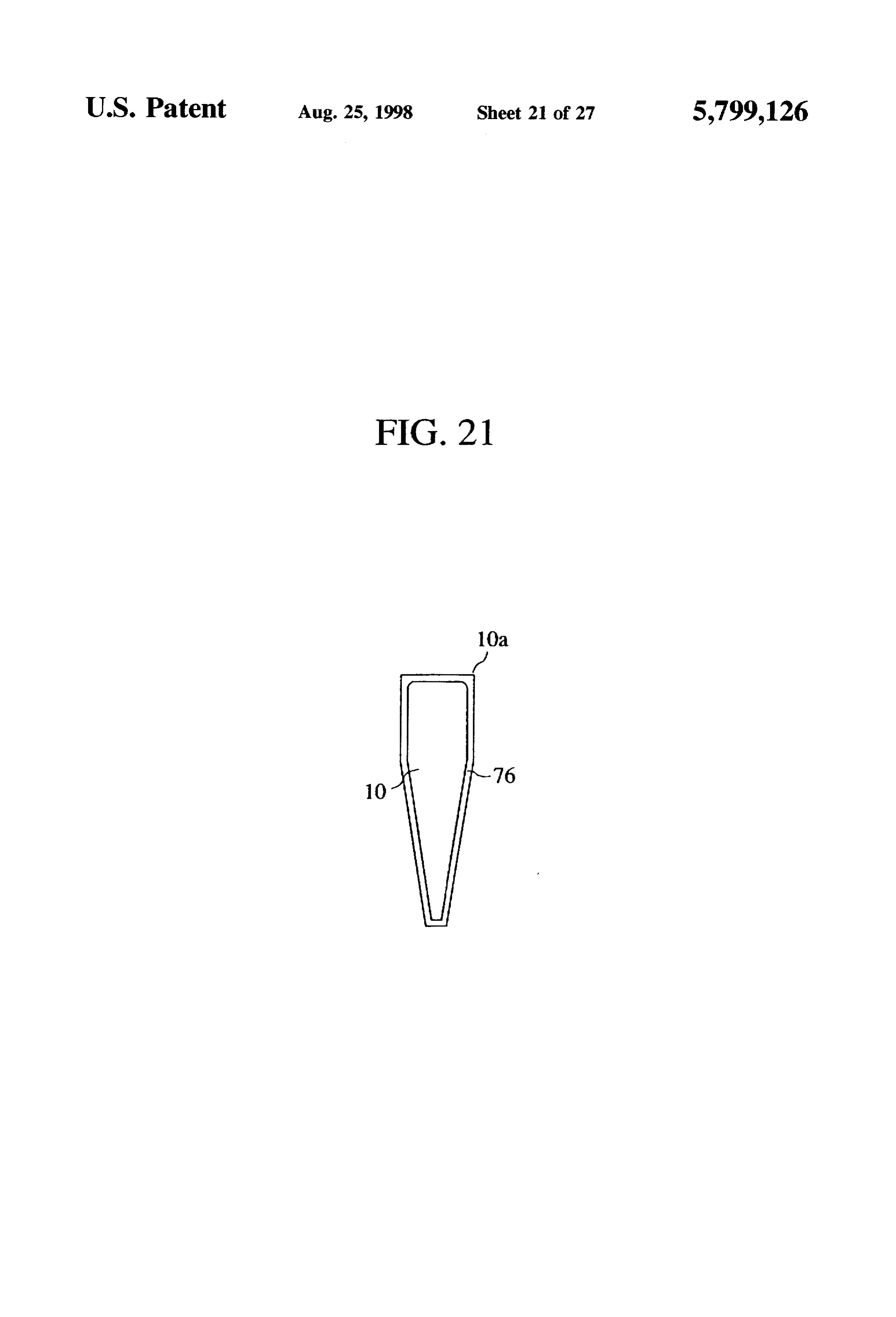
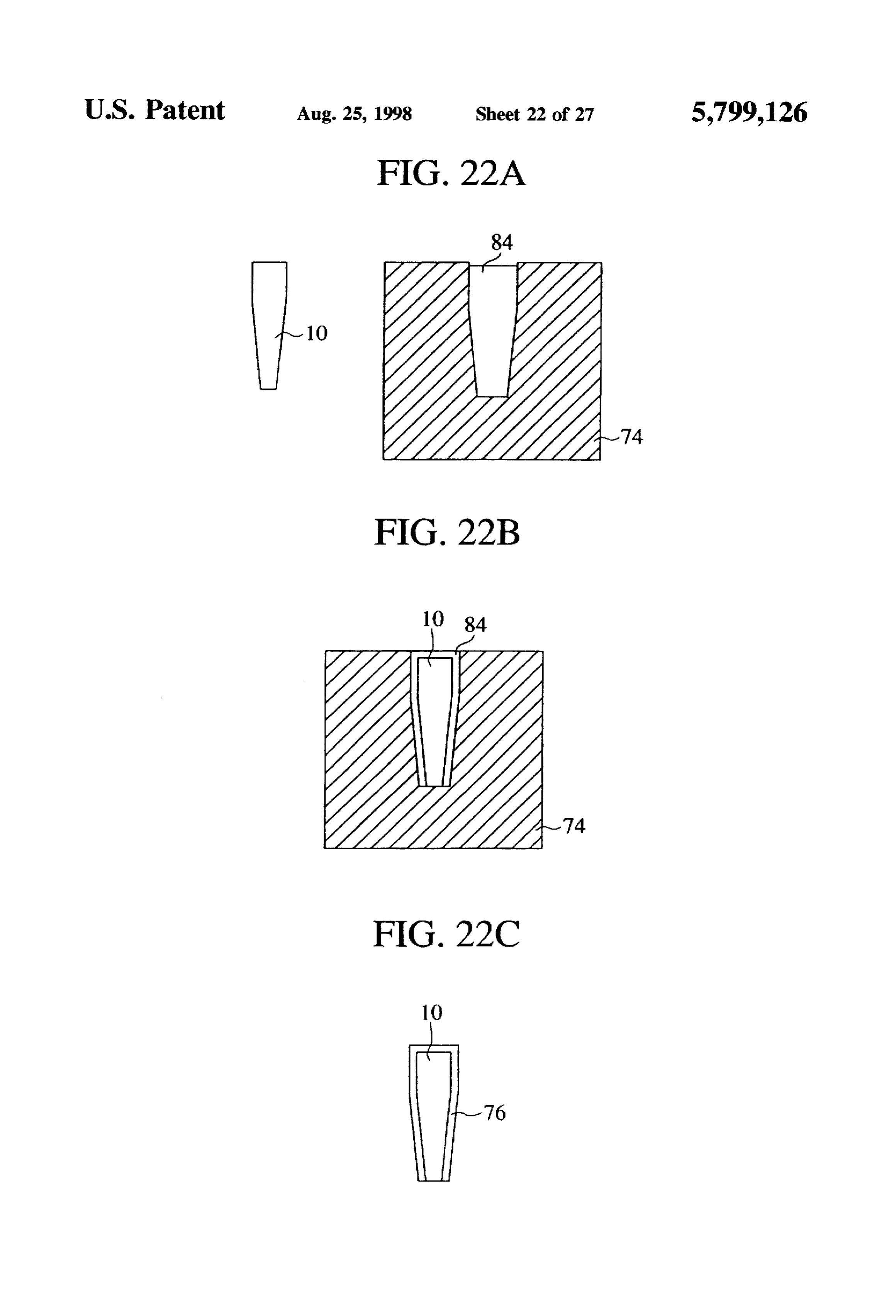
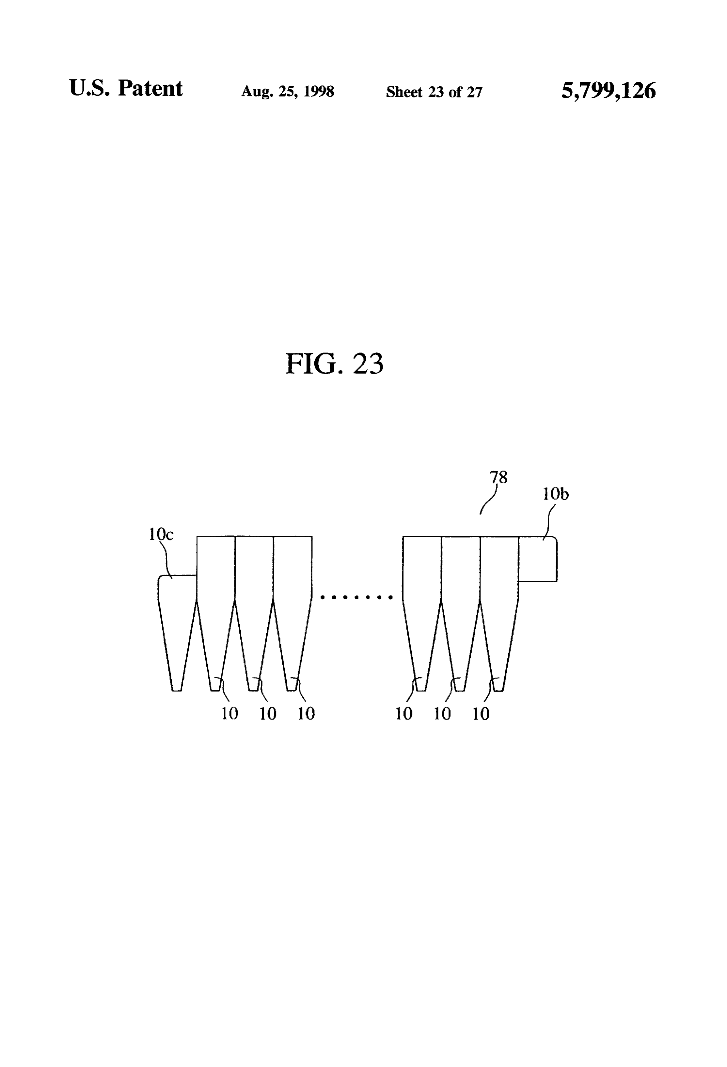
FIG. 21 is a sectional view of the light guide device In the first embodiment the light guide device 10 is a according to a thirteenth embodiment of the present inven transparent cylindrical body but it is not limited to this tion. shape. The light guide device 10 may be, as exemplified in FIGS. 22A to 22C are views explanatory of the method 35 FIG. 2A, generally cylindrical and a square pole only near for fabricating the light guide device according to the the incident end surface 12. As shown in FIG. 2B, the light thirteenth embodiment of the present invention. guide device 10 may be a hexagonal pole only near the exit FIG. 23 is a side view of the light guide device according end surface 14. Although not shown, the light guide device to a fourteenth embodiment of the present invention. 10 may be generally a polygonal pole. FIG. 24 is a view of a layout of a plurality of the light Thus variations of the light guide device 10 can be guide devices according to the fourteenth embodiment. proposed, and an optimum shape may be selected so that FIG. 25 is a sectional view of the liquid crystal display maximum incidence efficiency can be provided in optical device according to a fifteenth embodiment of the present coupling when the light guide device is combined with other invention. optical systems to constitute a light source device. FIG. 26 is a sectional view of the liquid crystal display 45 Next, FIG. 3 shows characteristic curves explaining the device according to a sixteenth embodiment of the present relationships between the shape of the light guide device 10 invention. of FIG. 1 and directivity of the directive light rays 18. FIG. 27 is a schematic sectional view of the conventional As apparent from the characteristic curves, as an area ratio light source device. 50 between the exit end surface 14 of the light guide device 10 and the incident end surface 12 is increased, directivity of
DETALED DESCRIPTION OF THE the directive light rays 18 is sharply improved. The rise of INVENTION the directivity is saturated around at an area ratio of 100. The present invention will be explained by means of When an area ratio exceeds 100, the directivity tends to be
oppositely decreased a little.
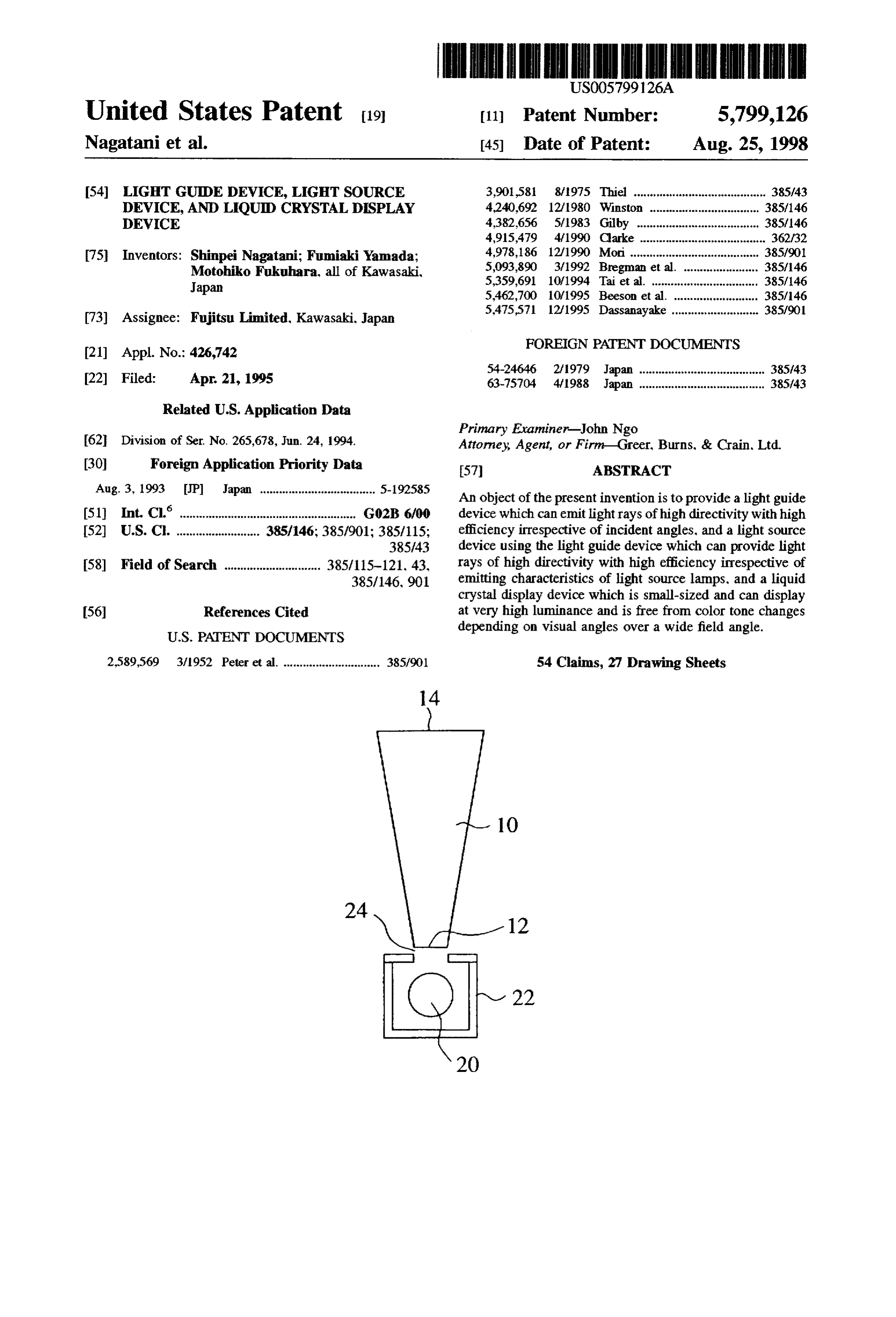
FIG. 1A is a perspective view of the light guide device Accordingly an optimum shape of the light guide device according to a first embodiment of the present invention. 10, especially an area ratio between the exit end surface 14 FIG. 1B is a sectional view of the light guide device of FIG. and the incident end surface 12 is selected for a required 1A. directivity on the characteristic curves of FIG. 3. The A light guide device 10 is a cylindrical transparent body directivity of the exit light rays can be improved up to the of, e.g., acrylic resin. One of two parallel end surfaces with practical level by setting an area of the exit end surface 14 each other is an incident end surface having a smaller area at 3 or more for an area 1 of the incident end surface 12. and a 1 mm-diameter, and the other is an exit end Surface Then the light source device according to a second having a larger area and a 6.2 mm-diameter. The length of embodiment of the present invention will be explained with the light guide device 10 is 100 mm. 65 reference to FIG. 4.
A method for providing high directivity by the use of this FIG. 4 shows a schematic sectional view of the light light guide device will be explained. source device according to the second embodiment.
Page 33
A substantial point light source 20, e.g., a metal halide at the plural exit end surfaces 14 in directive light rays lamp, is contained in a reflection box 22 having the inside respectively of high directivity oftl0°. wall covered with, e.g., a silver reflecting surface. An Thus in the light source device according to the third opening 24 in the form of a pinhole is formed in a surface embodiment using the light guide device 10 according to the of the reflecting box. 22. first embodiment, a substantial point light source 20, and the In the opening 24 in the form of an pinhole the light guide incident end surfaces 12 of a plurality of the light guide device 10 of FIG. 1 is disposed with the incident end surface devices 10 are optically coupled to each other through the 12 opposed to the substantial point light source 20 in the opening 26 in the form of a slit, whereby a plurality of light reflecting box. 22. It is preferable that a shape of the opening rays of high directivity can exit with high efficiency. 24 in the form of a pinhole agrees with a shape of the O Next the light source device according to a fourth embodi incident end surface 12 of the light guide device 10. ment of the present invention will be explained with refer Next, the operation of the light source device of FIG. 4 ence to FIG. 6.
will be explained. FIG. 6 is a schematic sectional view of the light source Light emitted from the substantial point light source 20 15 device according to the fourth embodiment of the present repeats reflection on the silver reflecting surface on the invention. Common members of the light source device inside wall of the reflection box. 22 and finally exits through according to the fourth embodiment with that of FIG.S have the opening 24 in the form of a pinhole to be incident on the common reference numerals not to repeat their explanation. incident end surface of the light guide device 10. As The light source device according to this embodiment is described above, the light which has entered the light guide 20 characterized in that a reflecting mirror is disposed outside device 10 exits at the exit end surface 14 in directive light the light source device according to the fourth embodiment. rays of directivity as high as +10°. An opening in the form of a slit is formed in a surface of Thus in the light source device according to the second a reflection box 28 containing a substantial point light source embodiment using the light guide device 10 according to the 20, and a plurality of the light guide devices 10 are arranged first embodiment, optical coupling between the incident end 25 adjacent to each other in a fan-shape along the slit. The surface 12 of the light guide device 10 and the substantial reflecting mirror 30 which is extended beyond the exit end point light source 20 through the opening 24 in the form of surfaces 14 of the light guide devices 10 are formed in a pinhole can realize a light source device which can emit one-piece with each other.
highly directive light rays with high efficiency. Then the operation of the light source device of FIG. 6 Then the light source device according to a third embodi 30 will be explained.
ment of the present invention will be explained with refer Light emitted from the substantial point light source 20 is ence to FIG. 5.
condensed in the opening in the form of a slit by the
FIG. 5A is a sectional front view of the light source device reflection box 28 to enter the incident end surfaces 12 of the according to the third embodiment. FIG. 5B is a sectional plural light guide devices 10, and exits at the plural exit end side view of the light source device according to the third 35 surfaces 14 as highly directive rays respectively of about embodiment. Common members of the light source device t10°. These exit rays respectively have high directivity but according to the third embodiment with that of FIG. 4 have are very divergent in the direction of propagation of their common reference numerals not to repeat their explanation. principal rays.
The light source device according to this embodiment is But exit light rays which are very divergent in the characterized in that the opening 24 in the form of a pinhole direction of propagation of the principal rays are reflected on of the second embodiment is replaced by an opening in the the reflecting mirror 30 into substantially parallel rays 31. form of a slit, and a plurality of light guide devices are because the reflecting mirror 30 extended beyond the exit disposed in the opening in the form of a slit. end surfaces 14 of the light guide devices 10 has surface That is, the opening 26 in the form of a slit is formed in 45 angles suitably set at parts thereof. a surface of a reflection box 22 containing a substantial point In the light source device according to the fourth embodi light source 20. The opening 26 in the form of a slit has a ment using the light guide devices 10 according to the first width equal to a size of the incident end surface of each light embodiment, the incident end surfaces 12 of a plurality of guide device 10 and a length some times the size. In the light guide devices 10 and the substantial point light source opening 26 in the form of a slit a plurality of the light guide 20 are optically coupled to each other through the opening devices 10 are disposed adjacent to each other in a fan-shape 50 26 in the form of a slit. and the reflecting mirror 30 is along the slit with the incident end surfaces 12 opposed to provided for reflecting the exit light rays from the exit end the substantial point light source 20 in the reflection box 22. surfaces 14, whereby substantial parallel rays 31 of high Next the operation of the light source device of FIG.5 will directivity can be emitted with high efficiency. The presence be explained. 55 of the reflecting mirror 30 allows the light source device Light emitted from the substantial point light source 20 itself to be small-sized because the light guide device 10 is repeats reflection on a silver reflection surface on the inside sufficiently small.
surface of the reflection box 22 as in the second In the fourth embodiment, exit light rays of high direc embodiment, and exits through the opening 26 in the form tivity whose principal light rays are very divergent are of a slit. The opening 26 in the form of a slit, which is larger formed into substantial parallel rays 31 by the reflecting than the opening 24 in the form of a pinhole, facilitates the mirror 30. But in the case that the principal light rays from exit of the light source light. That is, reduction of times of the plural exit end surfaces 14 are relatively less divergent, the reflection within the reflection box 22 decreases light assistant members 32 in the form of prisms provided by absorption by the silver reflecting surface. The efficiency of transparent bodies in various shapes as shown in FIG.7 may incidence of the light on the incident end surfaces 12 of the 65 be disposed, in place of the reflecting mirror 30, on the plural light guide devices 10 is accordingly improved. The forward ends of the exit end surfaces 14 of the respective light which has entered the plural light guide devices 10 exit light guide devices 10.
Page 34
That is, in the case that the principal exit light rays are too surface of an about 45 point angle on which an A1 divergent, and the exit principal light rays from those of the reflecting surface 36 is formed by, e.g., A1 evaporation so light guide devices 10 on the ends are largely inclined, the that light passing through the rectangular pole-shaped light exit light rays are totally reflected at diffraction points, e.g., guide member 34 is normally reflected. Above the A1 at the point A in FIG. 7. in directions where they are made reflecting surface 36 there is disposed the light guide device ineffective. But in the case that the principal light rays are 10 with the incident end surface 12 opposed to the A1 relatively less divergent, the assistant members 32 in the reflecting surface 36. Thus a substantial point light source 20 form of a prism of a triangle pole or rectangular pole and the incident end surface 12 of the light guide device 10 selected in accordance with inclinations of the principal exit are optically coupled with each other. light rays are provided on the forward ends of the exit end O A length of the rectangular pole-shaped light guide mem surfaces 14 of the respective light guide devices 10, whereby ber 34 is shortened or elongated, whereby a positional directions of the principal exit light rays of the exit light rays relationship between the light guide device 10 and the from the exit end surfaces 14 of the respective light guide substantial point light source 20 can be varied within a range devices 10 can be corrected to be substantially parallel rays which is not so wide as that provided by the optical fiber 33.
In the light source device according to the sixth embodi
Then the light source device according to a fifth embodi ment using the light guide device 10 according to the first ment of the present invention will be explained with refer embodiment, the rectangular pole-shaped light guide mem ence to FIG. 8. ber 34 is disposed as a light guide component for optically FIG. 8 is a schematic sectional view of the light source coupling the incident end surface 12 of the light guide device device according to the fifth embodiment. Common mem 10 with the substantial point light source 20, and a length, bers of the fifth embodiment with the light source device of etc. of the light guide member are adjusted, whereby light FIG. 4 have common reference numerals not to repeat their rays of high directivity can be emitted from a set position explanation. distant from the substantial point light source 20 with high The light source device according to the fifth embodiment 25 efficiency.
is characterized in that a flexible optical fiber is disposed, as Thus, in the light source device according to the sixth a light guide component, between the opening 24 in the form embodiment using the light guide device 10 according to the of a pinhole of the light source device according to the first embodiment, the rectangular pole-shaped light guide above-described second embodiment, and the incident end member 34 as a light guide component which optically surface 12 of the light guide device 10, which optically 30 couples the incident end surface 12 of the light guide device couples both members 24, 10. 10 with the substantial point light source 20, and a length of That is, the optical fiber 33 as a light guide component is which are adjustable is disposed, whereby light rays of high disposed between the pinhole-shaped opening 24 and the directivity can be emitted with high efficiency in a pre incident end surface 12 of the light guide device 10 to scribed direction at a prescribed position distant from the optically couple with each other. The optical fiber 33 is 35 substantial point light source 20.
flexed, or a length of the optical fiber 33 is shortened or As shown in FIG. 9A, the A1 reflecting surface 36 is elongated, whereby an optimum positional relationship provided on the slant surface on the forward end to change between the light guide device 10 and a substantial point a direction of light transmitted the rectangular pole-shape light source 20 can be set as required. light guide member 34, but in place of the A1 reflecting Thus, in the light source device according to the fifth surface 36 a right angle prism 38 having an A1 reflecting embodiment using the light guide device 10 according to the surface 36 formed on the slant surface by A1 evaporation first embodiment, the optical fiber 33 as a light guide may be provided on the end surface of the rectangular component which optically couples the incident end surface pole-shaped light guide member 34. The experiment con 12 of the light guide device 10 with the substantial point ducted by the inventors of the present invention shows that light source 20, and a length and flexure of which are 45 the case of FIG.9B where the right angle prisms 38 with the adjustable is disposed, whereby light rays of high directivity A1 reflecting surface 36 on the slant surface is provided on can be emitted with high efficiency in a prescribed direction the forward end surface of the rectangular pole-shaped light at a prescribed position distant from the substantial point guide member 34 could provide exit light rays with high light source 20. efficiency than the case of FIG. 9A where the A1 reflecting Then the light source device according to a sixth embodi 50 surface 36 is formed on the slant surface on the forward end ment of the present invention will be explained with refer of the rectangular pole-shaped light guide member 34. ence to FIG. 9. In these case's, taking into consideration optical coupling FIG. 9A shows a schematic sectional view of the light of the rectangular pole-shaped light guide member 34 with source device according to the sixth embodiment, and FIG. the right angle prism 38 it is preferable that the light guide 9B shows a schematic sectional view of a variation of the 55 device 10 has a rectangular pole shape only near the incident sixth embodiment. Common members of the light source end surface as shown in FIG. 2A.
device according to this embodiment with the light source The light source device according to a seventh embodi device of FIG. 8 are represented by common reference ment of the present invention will be explained with refer numerals not to repeat their explanation. ence to FIG. 10.
The light source device according to this embodiment is FIG. 10A is a front sectional view of the light source characterized by the use of a rectangular shaped-light guide device according to the seventh embodiment, and FIG. 10B member as a light guide component in place of the optical is a side sectional view thereof. Common members of the fiber 33 of the light source device according to the fifth light source device according to this embodiment with that embodiment. of FIG. 4 are represented by common reference numerals not That is, the rectangular pole-shaped light guide member 65 to repeat their explanation.
34 contacts an opening 24 in the shape of a pinhole on one The light source device according to the seventh embodi end surface, and has the other end surface formed in a slant ment is characterized in that a linear light source is used in
Page 35
place of the substantial point light source 20 of the second 40 in the same direction of the linear light source 40. The embodiment, and a plurality of openings in the shape of a stripe-shaped opening 44 has a width some times a size of pinhole are arranged along the linear light source. the incident end surfaces 12 of the light guide devices 10 and That is, the linear light source 40 in the form of a is extended along the linear light source 40 depthwise of the fluorescence tube is contained in a reflection box 42 having 5 drawing.
the inside wall coated with a silver reflecting surface. A The main cause for lowering efficiency of source light plurality of openings 24 in the shape of a pinhole are formed emission from the reflection box is increases in light absorp at a certain interval in a surface of the reflection box 42 along tion which take place due to multiple reflection in the the linear light source 40. reflection box when the source light reflects on the reflecting Light guide devices 10 are disposed respectively in the 10 mirror. The stripe-shaped opening 44 structurally has a plural pinhole-shaped openings 24 with the incident end larger opening, so that the source light has less reflecting surfaces 12 opposed to the linear light source 20 in the times within the reflection box 42, which facilitates the reflection box. Accordingly a plural number of the exit end emission of the source light out of the reflection box 42 more surfaces 14 of the plural light guide devices 10 are arranged than through the pinhole-shaped openings 24 and the slit linearly on a set level. Light rays of high directivity are 15 shaped openings 26. Accordingly higher efficiency and emitted with high efficiency from the respective plural exit higher luminance can be provided.
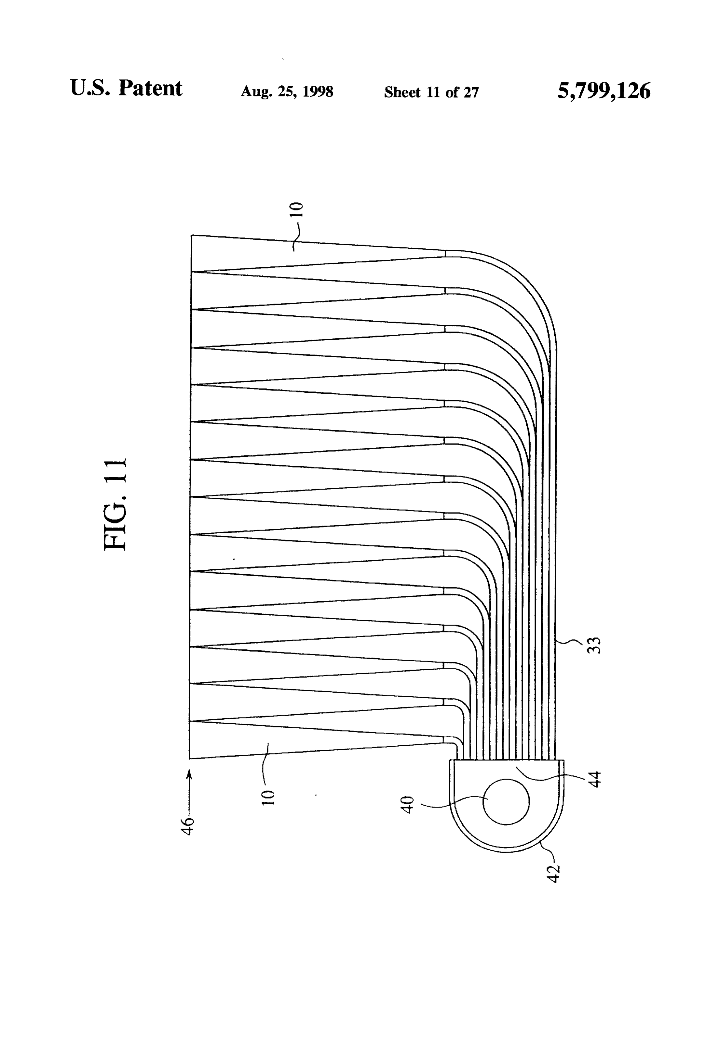
end surfaces 14 linearly arranged. A plurality of bundles of the optical fiber 33 are disposed In the light source device according to the seventh in the stripe-shaped opening 44 and optically couple the embodiment using the light guide devices 10 of the first stripe-shaped opening 44 and the incident end surfaces 12 of embodiment, the linear light source 40 is used as the light the plural light guide devices 10. The respective optical source, and the incident end surfaces 12 of the plural light fibers of each bundle are adjusted in terms of elongation and guide devices 10 and the linear light source 40 are optically flexure so that the exit end surfaces 14 of the plural light coupled with each other through the plural pinhole-shaped guide devices 10 are arranged in a matrix, and the exit end openings 24 formed along the linear light source 40, surfaces 14 are on a set level. In other words, the plural exit whereby light rays of high directivity can be emitted with 25 end surfaces 14 in the matrix define a single plane exit high efficiency from the plural end surfaces 14 arranged surface 46.
linearly on a set level. In the light source device according to the eighth embodi In place of the plural pinhole-shaped openings 24 in the ment using the light guide devices according to the first seventh embodiment, a plurality of the openings in the shape 30 embodiment, the stripe-shaped opening 44 with a large of a slit may be opened normal to the linear light source 40 opening area is used, whereby light rays of directivity can be and at a set interval along the linear light source 40. more efficiently emitted from the exit end surfaces 14 and In this case a plurality of light guide devices 10 are fibers can have higher luminance, while the respective optical disposed adjacent to each other in each of the slit-shaped 33 optically coupling the linear light source 40 and the opening 26, and in addition a plurality of light guide devices 35 plural light guide devices 10 are adjusted in terms of 10 are disposed along the linear light source 40, so that a 14 arrangedand elongation flexure, whereby the plural exit end surfaces in a matrix can define a single plane exit surface plurality of the exit end surfaces 14 of the light guide devices 46.
10 are arranged in a matrix. Light rays of high directivity are emitted with high efficiency from the respective plural exit In this case, to arrange the exit end surfaces 14 in a matrix end surfaces 14 arranged in a matrix. without any gap between each of the exit end surfaces and its adjacent
But although the exit light rays from the plural exit end 10 has a hexagonal one, it is preferable that each light guide device surfaces 14 arranged in a matrix respectively have high shape or a rectangular shape only near directivity, their primary light rays are widely diverged, and the incident end surface 12.
it is preferable to dispose a reflecting mirror on the outside ofThe light source device according to a ninth embodiment of the light source device to convert the light rays into FIGS. 12 and invention 45 the present
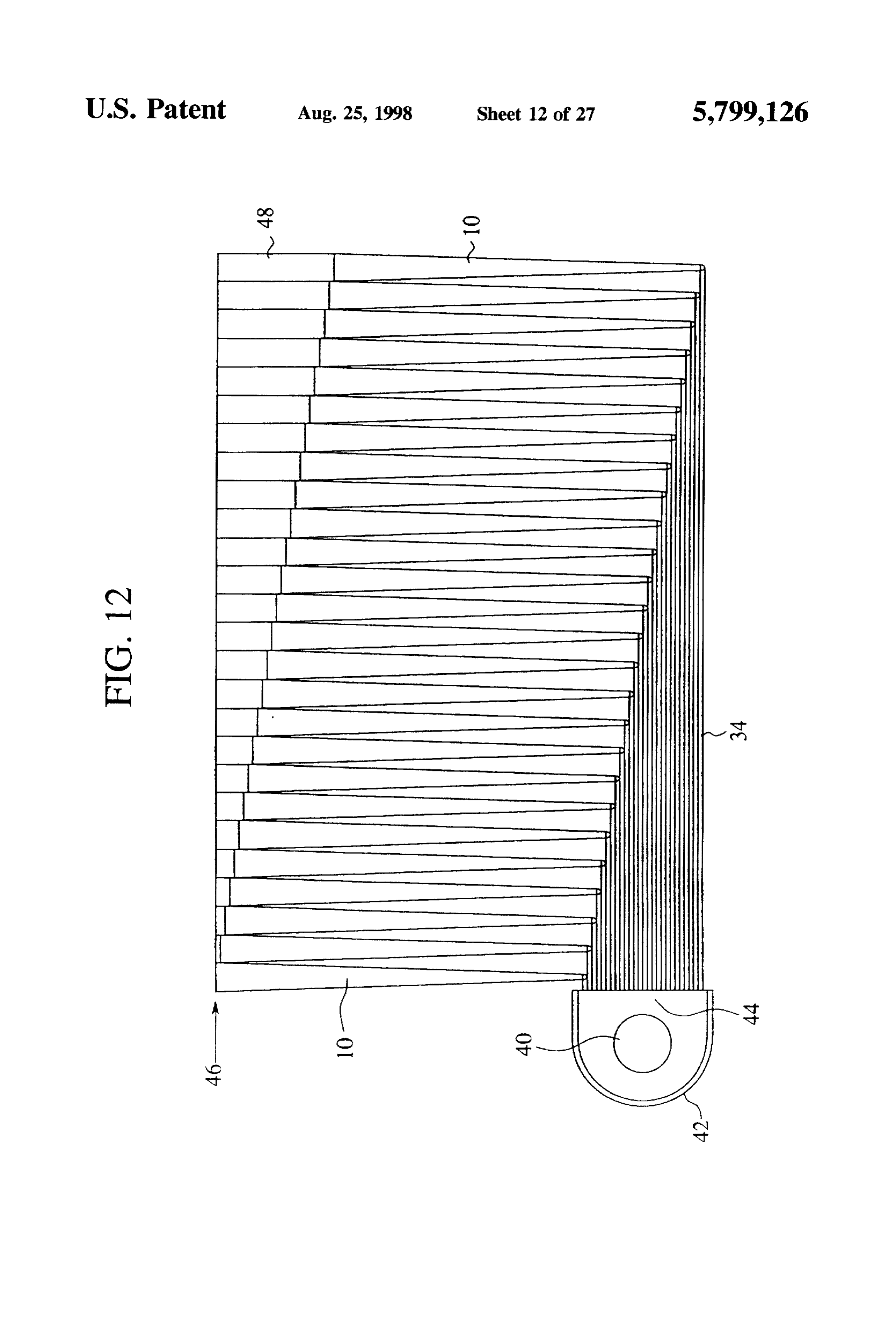
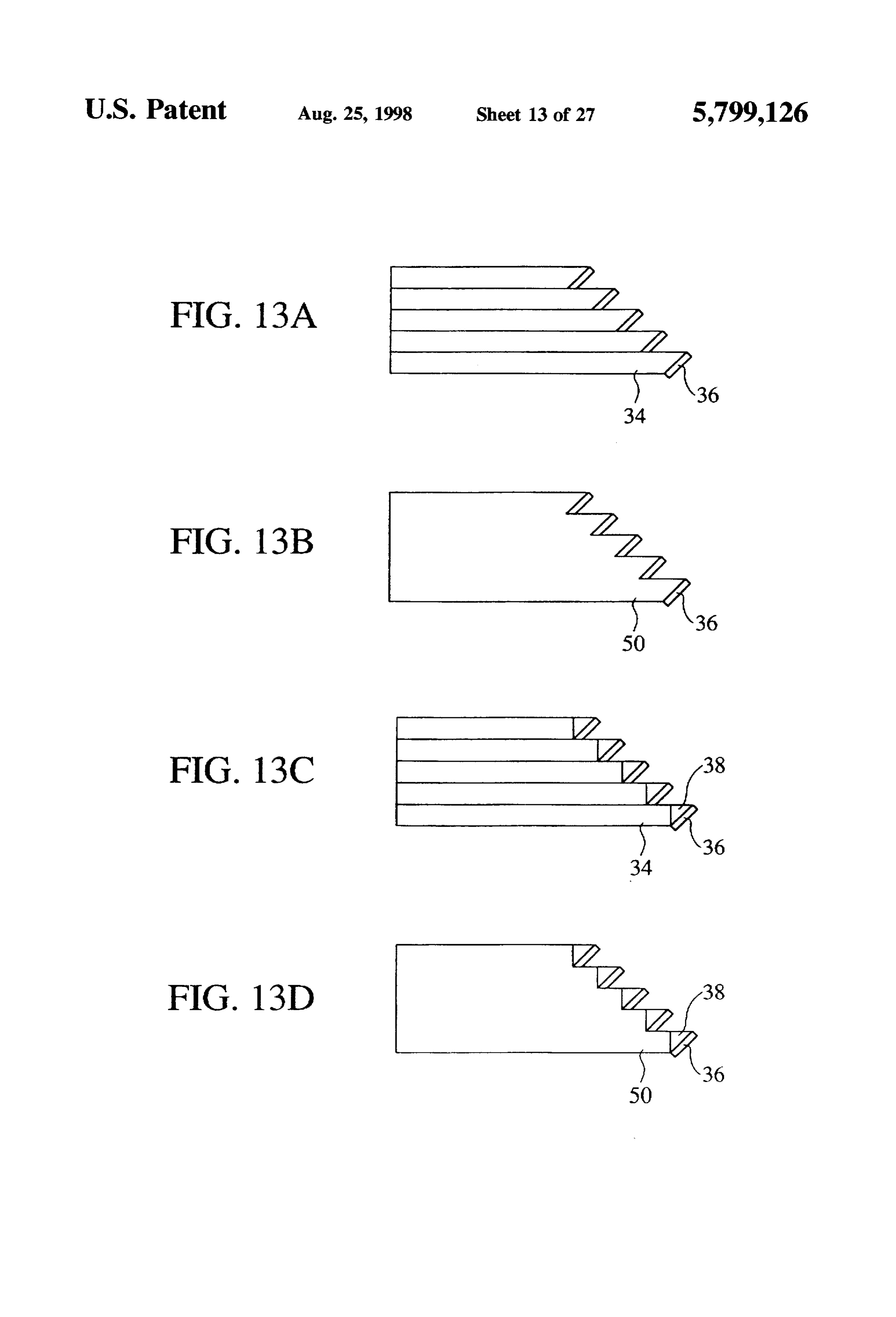
will be explained with reference to substantially parallel rays, as is done in the fourth embodi ment. FIG. 12 is a schematic sectional view of the light source Then the light source device according to an eighth partial device according to the ninth embodiment. FIG. 13A is a embodiment of the present invention will be explained with 50 memberenlarged of the view of a rectangular pole light guide light guide device, and FIGS. 13B to D are reference to FIG. 11.
variations of the rectangular pole light guide member. Com
FIG. 11 is a schematic sectional view of the light source mon members of the ninth embodiment with the light source device according to the eighth embodiment of the present devices of FIGS. 9 and 11 are represented by common invention. Common members of the light source device reference numerals not to repeat their explanation. according to this embodiment with the light source devices 55 The light source device according to the this embodiment of FIGS. 8 and 10 are represented by common reference is characterized in that a plurality of the rectangular pole numerals not to repeat their explanation. light guide members 34 of the fifth embodiment are arranged The light source device according to the eighth embodi in place of the optical fibers 33 of the eighth embodiment. ment is characterized in that an opening in the shape of a That is, a plurality of the rectangular pole light guide stripe is formed in place of a plurality of pinhole-shaped members 34 are arranged adjacent to each other without any openings 24 of the seventh embodiment, and a plurality of gap between each of the light guide members 34 and its bundles of the optical fibers 33 as light guide members of the adjacent one in a stripe-shaped opening 44 formed in a fifth embodiment are arranged between the stripe-shaped surface of a reflection box 42 containing a linear light source opening and the incident end surfaces 12 of a plurality of the 40 normal to the linear light source 40. light guide devices 10. 65 As shown in FIG. 13A, the A1 reflecting surface 36 of That is, the stripe-shaped opening 44 is formed in a FIG. 9A is formed on an about 45°-slant surface on the surface of a reflection box 42 containing a linear light source forward end of each of the rectangular pole light guide
Page 36
members 36. Light from the linear light source 40 through source light to increase luminance of exit light rays. A the rectangular pole light guide members 34 reflects on the plurality of rectangular pole-shaped light guide members 34 A1 reflecting surfaces 36 to be incident on the incident end are arranged in two directions normal to the stripe of the surfaces of a plurality of the light guide devices 10 arranged stripe shaped opening 44 formed in a surface of a reflection above the A1 reflecting surfaces 36. The rectangular pole box 42 from the opening 44.
light guide member 34 are respectively adjusted in terms of On both end surfaces of each rectangular pole-shaped length, so that the exit end surfaces 14 of the plural light light guide member 36 there are provided right angle prisms guide devices 10 are arranged in a matrix. 38 having the A1 reflecting surfaces 36 of, e.g., FIG. 13C A transparent assistant member 48 in the shape of a pole provided on a slant surface, so that light from the linear light is provided on the forward end of the exit end surface 14 of O source 40 which has passed through the rectangular pole each light guide device 10. The assistant members 48 are shaped light guide member 34 is incident on the incident end adjusted in terms of length to be on the same level so as to surfaces 12 of the light guide devices 10 arranged above the define a single plane exit surface 46. right angle prisms 38.
In the light source device according to the ninth embodi As in the ninth embodiment, the respective rectangular ment of the present invention using the light guide devices 15 pole-shaped light guide members 34 are adjusted in terms of 10 of the first embodiment, the stripe-shaped opening 44 is length, so that the exit end surfaces 14 of the plural light used, the linear light source 40 and the incident end surfaces guide devices 10 are arranged in a matrix. 12 of the plural light guide devices 10 are optically coupled As in the ninth embodiment, assistant members 48 in the with each other by the rectangular pole light guide members form of transparent poles are disposed on the forward 34, while lengths of the pole-shaped assistant members 48 20 portions of the exit end surfaces 14 of the light guide devices on the forward ends of the exit end surfaces 14 are adjusted 10 and are adjusted to have set lengths, so that the pole so that the members 48 are on the same level, whereby, as shaped assistant members 48 are on a set level and define a is in the eighth embodiment, the plural exit end surfaces 14 single plane exit surface 46.
arranged in a matrix define a single plane exit surface 46. In the light source device according to the tenth embodi In the ninth embodiment, in place of a plurality of 25 ment of the present invention using the light guide devices rectangular pole-shaped light guide members 34 arranged 10 of the first embodiment, the plural rectangular pole adjacent to each other without any gap in FIG. 13A, a light shaped light guide members 34 are arranged even in two guide member 50 having the rectangular pole-shaped light directions from the stripe-shaped opening 44, but the light guide members 34 formed in one-piece in FIG. 13B may be source device can still achieve the same advantageous used. In this case as well, it is necessary that the forward effects as the ninth embodiment. In this case, since the ends of the light guide member 50 optically coupled with the 30 reflection box 42 containing the plural linear light sources 40 incident end surfaces 12 of the plural light guide devices 10 is disposed below the plural light guide devices 10, the are formed in about 45 slant surfaces on which A1 reflect reflection box 42 can be invisibly hid behind the plural light ing surfaces 36 are respectively. guide devices 10 as viewed on the side of the exit surface 46. As shown in FIG. 13C, the right angle prisms 38 having 35 That is, the light source device has an advantage that the the A1 reflecting surfaces 36 on the slant surfaces in FIG.9B device as a whole can be diminished in size in the surround may be disposed on the forward surfaces of the rectangular ings as the non-light emitting part.
pole-shaped light guide members 36 in place of the A1 In the ninth and the tenth embodiments, taking into reflecting surfaces 36 on the forward slant surfaces of the consideration that the pole-shaped assistant members 48 rectangular pole-shaped light guide members 36 in FIG. arranged in a matrix to define the single exit surface 46 it is 13A. preferable that the pole-shaped assistant members 48 are As shown in FIG. 13D. in place of the plural rectangular hexagonal pole-shaped or rectangular pole-shaped at least pole-shaped light guide members 34 disposed adjacent to near the exit end surfaces 46.
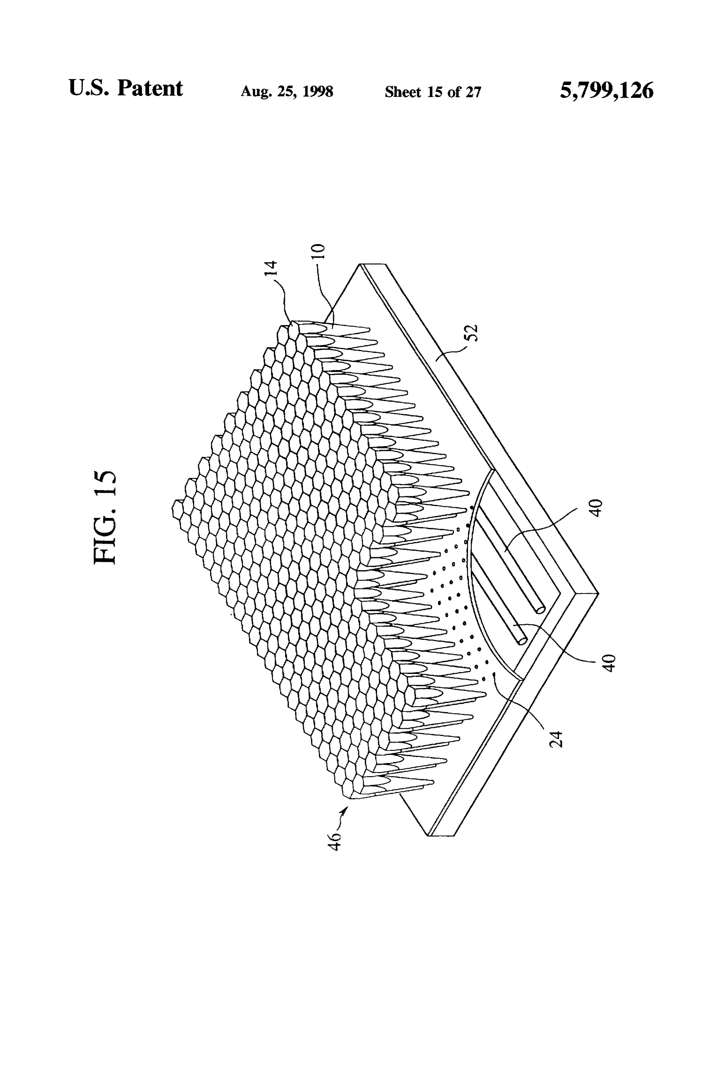
each other without any gap therebetween in FIG. 13C, a light The light source device according to an eleventh embodi guide member 50 with the rectangular pole-shaped light 45 ment of the present invention will be explained with refer guide members 34 formed in one-piece may be used. In this ence to FIG. 15.
case as well, it is necessary that right angle prisms 38 FIG. 15 is a perspective view of the light source device respectively with the A1 reflecting surfaces 36 formed on the according to the eleventh embodiment. Common members slant surfaces are disposed on the forward surfaces optically of the light source device according to this embodiment with coupled with the incident end surfaces of the plural light 50 that of FIG. 10 are presented by common reference numerals guide devices 10. not to repeat their explanation.
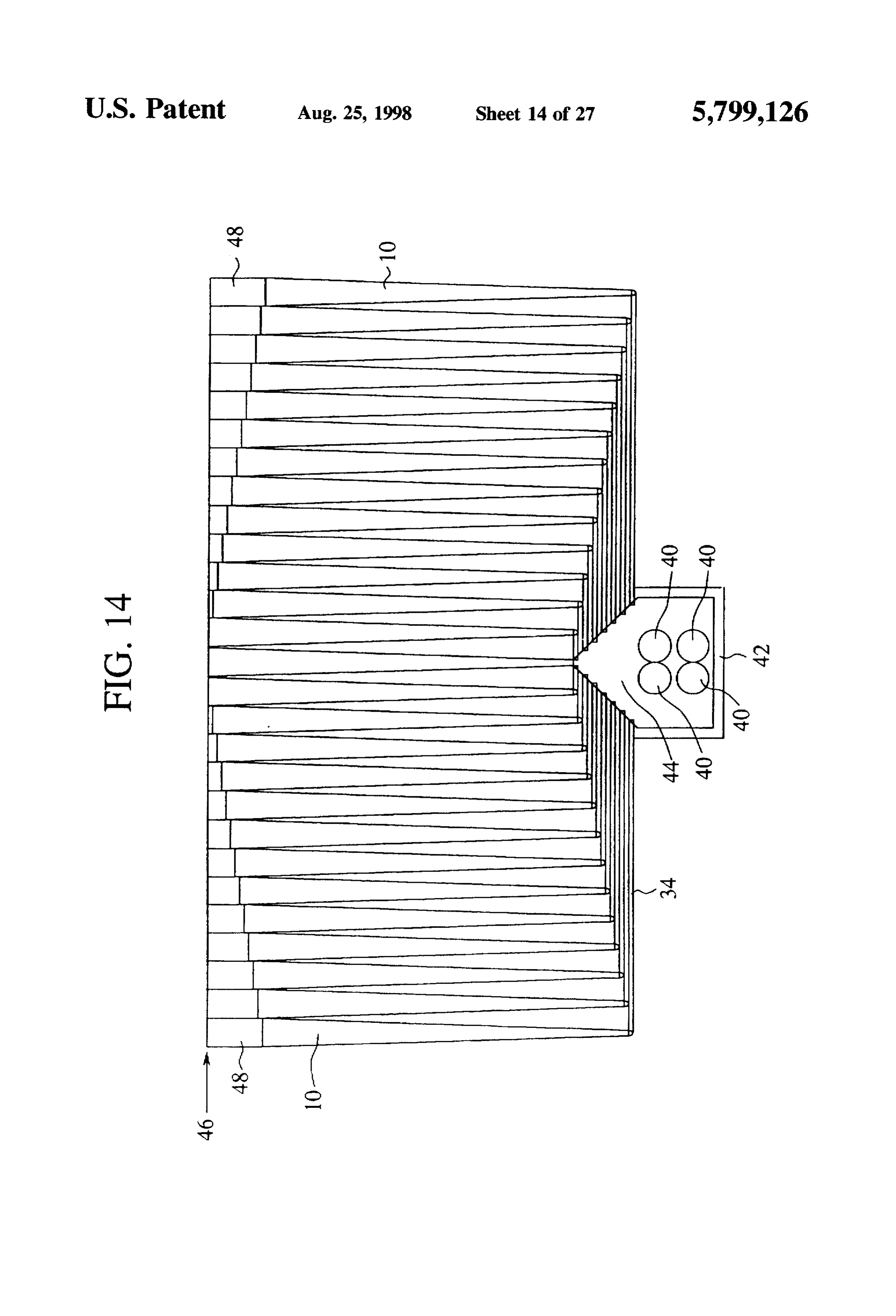
Then the light source device according to a tenth embodi The light source device according to this embodiment is ment of the present invention will be explained with refer characterized in that the pinhole-shaped openings 24 of the ence to FG, 14. seventh embodiment, which are linearly formed, are formed FIG. 14 is a schematic sectional view of a light source 55 in matrix.
device according to the tenth embodiment. Common mem That is, a plurality of parallel lines of light sources 40 are bers of the light source device according to this embodiment contained in a reflection box. 52 having the inside wall with that of FIG. 12 are represented by common reference coated with a silver reflecting surface. A number of pinhole numerals not to repeat their explanation. shaped openings 24 are formed in a surface of the reflection In the ninth embodiment the plural rectangular pole box 52. In the respective pinhole-shaped openings 24 there shaped light guide members 34 are extended in one direction are disposed light guide devices 10 with the incident end from the stripe-shaped opening 44, but in this embodiment surfaces 12 opposed to a linear light source 40 in the rectangular pole-shaped light guide members 34 are reflection box 52. The exit end surfaces 14 of the plural light extended in two directions from a stripe-shaped opening 44. guide devices 10 are on the same level to define a single This is characteristic of this embodiment. 65 plane exit surface 46.
That is, a plurality of linear light sources 40 are contained The light guide devices 10 are, as shown in FIG. 2B, in a reflection box 42. This is intended to raise luminance of hexagonal near the exit end surfaces 14, and the exit end
Page 37
surfaces 14 defining the exit surface 46 are arranged in a Then, a specular plate 72 which is made from nonadhe matrix without any gap therebetween. sive material to acrylic resin is put on the exit surface 46 In the light source device according to the eleventh with acrylic resin applied to (FIG. 18B). Then UV is radiated embodiment of the present invention using the light guide to solidify the acrylic resin, and next the specular plate 72 is devices 10 of the first embodiment, a number of light guide put off. Thus the light guide device according to the twelfth devices 10 are disposed in a matrix in a number of pinhole embodiment is fabricated (FIG. 18C).
shaped openings 24 formed in the surface of the reflection The acrylic resin layer 66 may be integrated by acrylic box 52 containing the parallel plural linear light sources, polymerization adhesion as shown in FIG. 19. whereby the plural exit end surfaces 14 arranged in a matrix In this case, first the light guide devices 10 are arranged define the single plane exit surface 46 without the use of O in plane (FIG. 19A). A mixed liquid 80 of acrylic monomer light guide members. and a hardener is placed in a vessel 82 having the inside Next, the light guide device and the light source device bottom formed in speculum. Then the light guide devices 10 according to a twelfth embodiment of the present invention arranged with the exit surfaces faced downward (FIG. 19B). will be explained with reference to FIGS. 16 to 20. FIG. 16 15 The hardener is exemplified by, e.g., "Acryl Bond" by is a perspective view of the light source device according to Mitsubishi Rayon. Then the container is left at the room the twelfth embodiment. FIG. 17 is a partially enlarged temperature to let the polymerization adhesion start. After sectional view of the light source device according to the the acrylic resin layer 66 has been solidified, the container eleventh embodiment. FIG. 18 is a view explaining the 82 is put off, and the light guide device is formed (FIG. method for fabricating the light guide device according to 19C), the twelfth embodiment. FIG. 19 is a view explaining a 20 Next the operation of the light source device according to method for fabricating a light guide device using acrylic the twelfth embodiment will be explained with reference to polymerization adhesion. FIG. 20 is a view explaining the FG. 20.
operation of the light source device according to the twelfth In the case that the acrylic resin layer 66 is not provided embodiment.
As shown in the eleventh embodiment, since the exit 25 betweenon the exit surface 46 (FIG.20A), when gaps 70 are present surface 46 defined by the light guide devices 10 is consti the light the light guide devices 10, light which has entered guide devices 10 are totally reflected on the side tuted by hexagonal pole-shaped light guide devices 10, a surfaces of matrix layout can be made. But the exit end surface of the exits in the the gaps light guide devices 10. Accordingly no light 70 between the light guide devices 10. In respective light guide devices have fine curved surfaces 68 30 contrast to this case, in the case that the acrylic resin layer as shown in FIG. 17, and subtly varied sizes of the light guide devices occurring in their manufacturing process. 66 is formed integrally (FIG. 20B), because of a small Accordingly there is a possibility that the exit surface 46 refractive index difference between the light guide devices 10 and the acrylic resin layer 66, incident light is not totally may have gaps 70. reflected but can exit also at the gaps 70. Thus the exit Because of such fine curved surfaces 68 of the light guide 35 surface 46 can be free from disuniformity of luminances devices 10, a refractive index of light is changed in the fine which depend on the gaps 70 between the light guide devices curved surfaces 68, and directivity of the light is deterio 10.
rated. Because of gaps 70, the gaps 70 between the light Since the fine curved surfaces 68 of the light guide guide devices 10 are non-light emitting parts, and disuni devices 10 are planarized by application of acrylic resin, no formity of a luminance takes place on the exit surface 46. change is made to the refracting surface, and accordingly The light source device according to the twelfth directivity provided by the light guide devices 10 is not lost. embodiment, is characterized by an acrylic resin layer 66 on In addition, when the acrylic resin layer 66 is solidified, the the exit surface 46 defined by the light guide devices 10 specular plate is placed on the surface of the light guide formed in one-piece with the light guide devices 10 so as to devices 10, which prevents generation of fine convexities solve the above-described problems of the eleventh embodi 45 and concavities therein.
ment.
That is, a plurality of linear light sources 40 arranged in resin Thus according to the twelfth embodiment, the acrylic parallel with each other are accommodated in a reflection as thelayer 66 having substantially the same refractive index acrylic resin of the light guide devices 10 is provided box. 52 having the inside surface covered with a silver integral with the reflecting surface. A number of pinhole-shaped openings 24 50 46 defined by thelight guide devices 10 on the exit surface light guide devices 10. Accordingly the are formed in the surface of the reflection box 52. In the respective pin hole-shaped openings 24 the light guide light nance source device can have little disuniformity of a lumi and good directivity.
devices 10 are disposed with the exit end surfaces 12 directed to the liner light source 40 in the reflection box 52. To obtain the products of the light guide device which An about hundreds pum-thickness acrylic resin layer 66 is 55 have the directivity below about +20, it is preferable that a provided on a single flat exit surface 46 defined by the exit refractive index ratio between the resin layer and the light end surfaces 14 of the plural light guide devices 10. guide device is above about 0.97. Then the method for fabricating the light guide device Then, the light guide device according to a thirteenth according to the twelfth embodiment will be explained with embodiment of the present invention will be explained with reference to FIG. 18. reference to FIGS. 21 and 22.
First the light guide devices 10 are arranged in plane. FIG. 21 is a sectional view of the light guide device Then a UV solidifying acrylic resin having a substantially according to the thirteenth embodiment. FIG. 22 is view equal refractive index to that of an acrylic resin forming the explaining the method for fabricating the light guide device light guide devices is applied to the exit surface 46 defined according to the thirteenth embodiment. by the light guide devices 10 (FIG. 18A). The UV solidi 65 The light guide device 10a according to the thirteenth fying acrylic resin is exemplified by, e.g., "3018" by Three embodiment is characterized in that the light guide device 10 Bond. according to the above-described first embodiment has the
Page 38
exterior surface covered with a coating layer 76 of a trans stituted by the end 10bhaving the upper shape, and the end parent silicone material of a lower hardness than the light 10c having the lower shape can have the same characteris guide device 10. tics as the other light guide devices. Accordingly no lumi The method for fabricating the light guide device accord nance disuniformity takes place.
ing to the thirteenth embodiment will be explained with Thus according to the fourteenth embodiment, a plurality reference to FIG. 22. of the light guide devices 10 are interconnected to each other First the light guide device 10 is formed of transparent in a line of the light guide devices 78. Accordingly non-light acrylic resin. Next, a mold 74 for the light guide device, emitting parts are absent, and groups of the light guide which is larger than the same by, e.g., about 0.5 mm is devices having a uniform luminance on the surface can be prepared, and then liquid silicone 84 is poured into the mold formed.
74 (FIG.22A). Next, the light guide device 10 is put in the In the fourteenth embodiment both ends 10b, 10c of a line mold 74 with the transparent silicone 84 loaded in, and in of the light guide devices 78 have partial shapes of the light this state the silicone is solidified (FIG.22B). Thus the light guide device, but it is possible that either one of both ends guide device 10a covered with the coating layer 76 of 15 of the line of the light guide devices has a partial shape of transparent silicone is completed (FIG.22C). the light guide device 10.
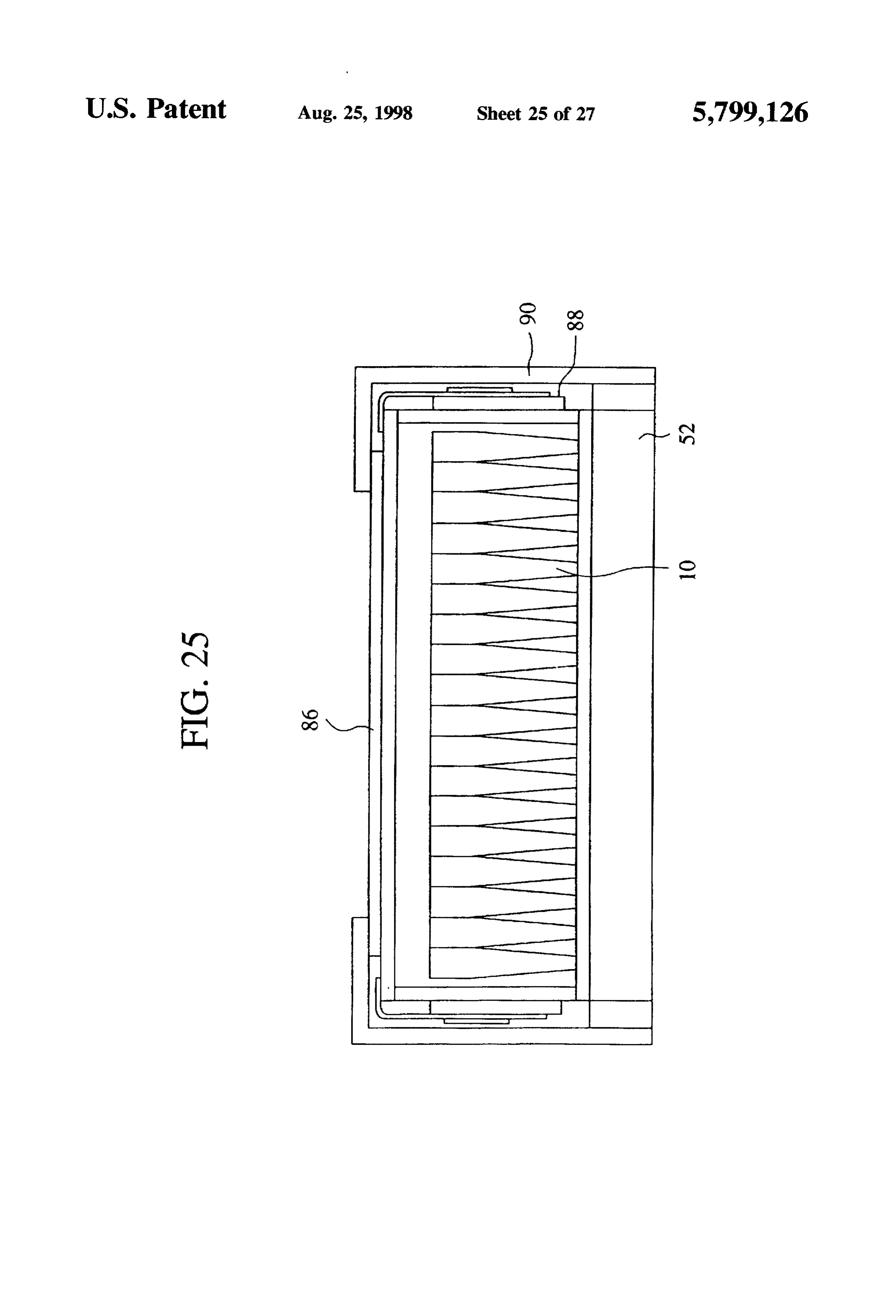
The arrangement of a plurality of the light guide devices The liquid crystal display device according to a fifteenth as in the above-described embodiment has a risk of forming embodiment will be explained with reference to FIG. 25. gaps 70 between each light guide device 10 and its adjacent FIG. 25 is a sectional view of the liquid crystal display ones. But coating a group of the light guide devices 10a of device according to the fifteenth embodiment. acrylic resin with the coating layer 76 as in the thirteenth The liquid crystal display device according to the present embodiment, the transparent silicone material forming the embodiment has a liquid crystal panel 86 disposed on an exit coating layer 76 is flexible enough to fully bury the gaps between each of the arranged light guide devices 10a and its end surface of a light source device of the eleventh embodi ment.
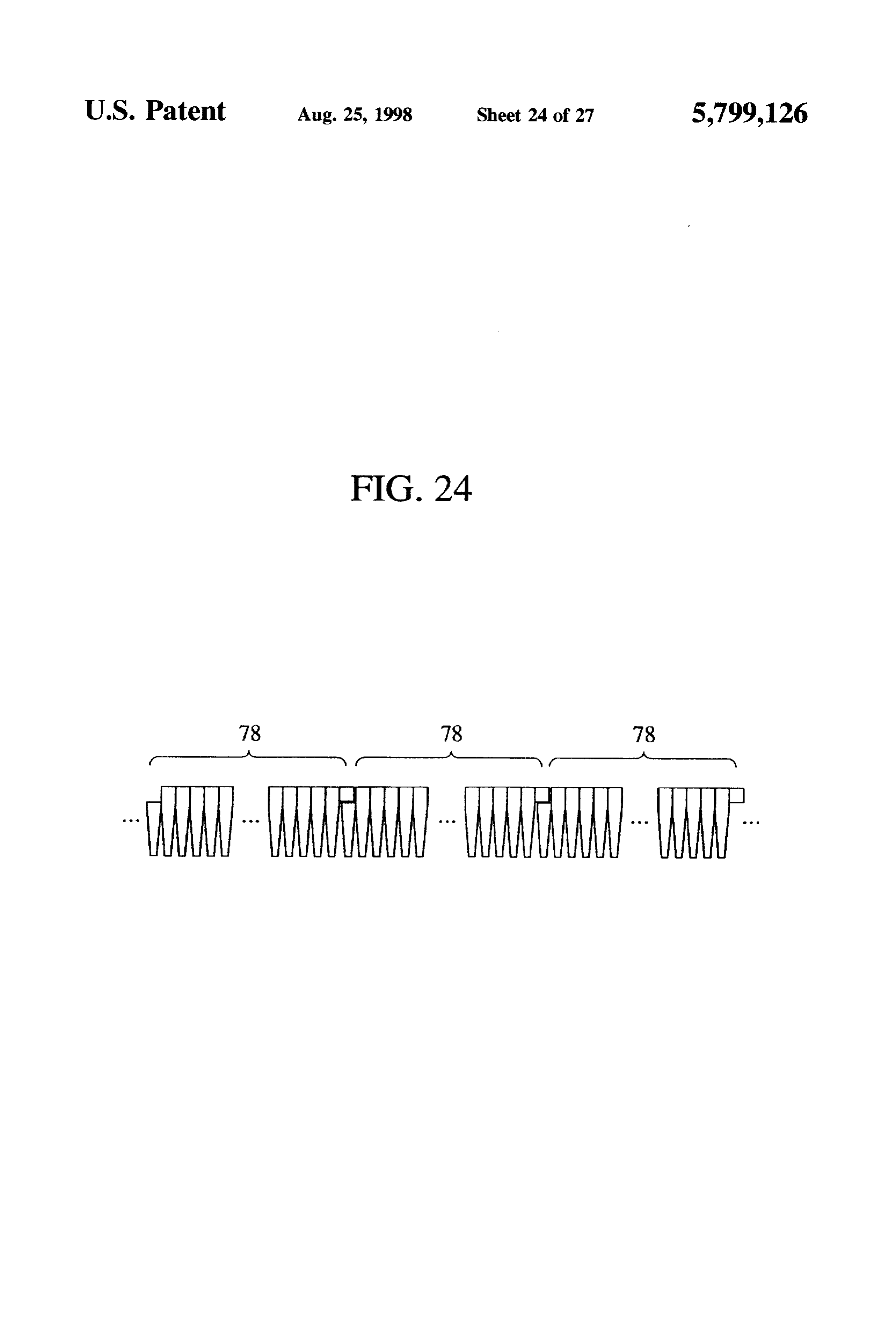
adjacent ones 10a. 25 That is, a plurality of parallelly arranged linear light Thus according to the thirteenth embodiment, the exterior sources (not shown) are accommodated in a reflection box surface of the light guide devices 10 are coated with the 52 having the inside surface coated with a silver reflecting coating layer 76 of a lower hardness, and the light source surface. A number of openings (not shown) in the form of device can have little luminance disuniformity. pinholes are formed in a surface of the reflection box 52 in Next, a fourteenth embodiment of the present invention 30 a matrix. In the respective openings in the form of pinholes will be explained with reference to FIGS. 23 and 24. there are disposed light guide devices 10 with the incident FIG. 23 is a side view of a light guide device according end surfaces opposed to the linear light sources in the to the fourteenth embodiment, and FIG. 24 is a view of a reflection box 52. The exit end surfaces of the plurality of layout of a plurality of the light guide devices according to light guide devices 10 define a single flat exit surface on the the fourteenth embodiment. 35 same level.
The light source device according to the fourteenth On the exit end surfaces of the respective light guide embodiment is characterized in that a plurality of the light devices there is sealed a liquid crystal material between two guide devices 10 are interconnected to each other in a line sheets of glass, and voltages are applied to electrodes of light guide devices 78 so as to solve the problem of the between the sheets of glass. Thus a liquid crystal panel 86 eleventh embodiment. which functions as a display device is formed. The liquid That is, the light guide devices 10 according to the first crystal panel 86 is connected to a liquid crystal drive circuit embodiment are interconnected to each other in a line, and 88. The liquid crystal display device has the exterior covered both ends of the line have partial shapes. A partial shape of by a metallic vessel 90.
one end 10b, and a partial shape of the other end 10c are 45 Thus, the liquid crystal display device according to the combined into substantially the same shape of the light fifteenth embodiment has the small-sized light source device guide devices 10. In each line of the light guide devices 78 which can emit highly directive light beams at high of FIG. 23, one end 10b has the upper one of the light guide efficiency, whereby the liquid crystal display device can be device divided in an upper and a lower part, and the other small in size and can display at very high luminance of end 10c has the lower one. above ten thousands cd/m. Such a liquid crystal display device is applicable to outdoor display boards, display
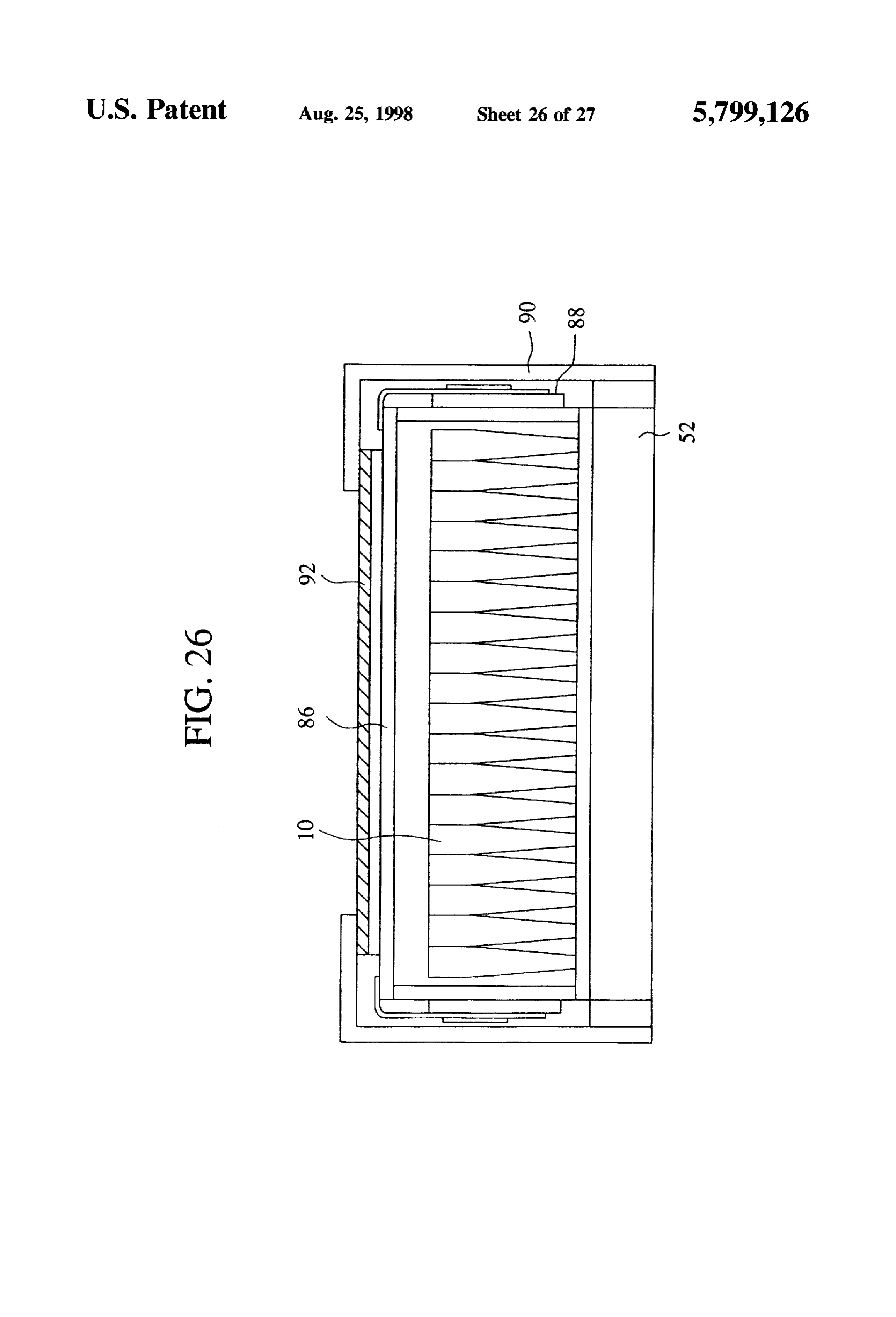
Such lines of the light guide devices 78 are sequentially boards arranged as in FIG. 24 to form a group of the light guide which have to be looked from a distance, etc. devices, and each group of the light guide devices 78 can be The liquid crystal display device according to a sixteenth made up. At the connection between each line of the light embodiment will be explained with reference to FIG. 26. guide devices 78 and its adjacent one, one light guide device 55 FIG. 26 shows a sectional view of the liquid crystal made up by the ends 10b, 10c is formed. display device according to the sixteenth embodiment. Then the operation of the light guide device constituted by The liquid crystal display device according to the present the ends 10b, 10c of each line of the light guide devices will embodiment is characterized in that a light diffusing sheet 92 be explained. is provided on the surface of the liquid crystal display device Light which has been incident on the lower part of the according to the fifteenth embodiment.
light guide devices 10 passes through the interior of the light That is, a plurality of parallelly arranged linear light guide device, increasing directivity. When the lightarrives at sources (not shown) are accommodated in a reflection box the joint surface with the end 10b having the upper shape of 52 having the interior surface coated with a silver reflecting the light guide device 10, the light is substantially perpen surface. In a surface of the reflection box there are formed dicular to the joint surface, and accordingly the light passes 65 a number of openings (not shown) in the form of pinholes in through the joint surface without lowering its intensity to be a matrix. Light guide devices 10 are provided in the number incident on the end 10b. Thus the light guide device con of openings in the form of pinholes with the incident end
Page 39
surfaces opposed to the linear light source in the reflection a first connection disposed on one end of the line of the box 52, so that a single flat exit surface. light guide devices, and having a partial shape of the On the exit end surfaces of the light guide devices 10 a light guide devices; and liquid crystal material is sealed between two sheets of glass, a second connection disposed on another end of the line and voltages are applied to respective electrodes between the 5 of the light guide devices, having a partial shape of the sheets of glass. Thus a liquid crystal panel 86 functioning as light guide devices which is different from that of the a display device is provided. Liquid crystal drive circuit 88 first connection, the second connection making up is connected to the liquid crystal panel 86 for driving the together with the first connection a shape substantially liquid crystal panel. On the liquid crystal panel 86 there is the same as that of the light guide device. provided a light diffusing sheet 92 for diffusing light beams 10 10. A light guide device according to claim 2, further of directivity which have exited from the light guide devices comprising a line of the light guide devices arranged in 10 and passed the liquid crystal panel. The liquid crystal parallel with each other, and formed integral to each other; display device has the exterior covered by a metallic vessel a first connection disposed on one end of the line of the
light guide devices, and having a partial shape of the
Thus, according to the sixteenth embodiment, the light 15 light guide devices; and diffusing sheet 92 is provided on the liquid crystal panel 86, a second connection disposed on another end of the line whereby directive beams which have exited the light guide of the light guide devices, having a partial shape of the devices 10 and passed through the liquid crystal panel are light guide devices which is different from that of the diffused, whereby the liquid crystal display device can be first connection, the second connection making up free from color tone changes depending on visual angles 20 together with the first connection a shape substantially over a wide field angle. the same as that of the light guide device. In the fifteenth and the sixteenth embodiments, the liquid 11. A light guide device according to claim 3, further crystal display devices use the light source device of the comprising a line of the light guide devices arranged in eleventh embodiment, but liquid crystal display devices can parallel with each other, and formed integral to each other; be fabricated by using directive light source devices which 25 a first connection disposed on one end of the line of the can emit light beams in plane. Liquid crystal display devices light guide devices, and having a partial shape of the can include the light source device of any one of the light guide devices; and above-described embodiments.
What is claimed is: a second connection disposed on another end of the line 1. A light guide device comprising a pole-shaped trans 30 of the light guide devices, having a partial shape of the parent cylindrical body having an incident end surface light guide devices which is different from that of the receiving light from a light source, and an exit end surface first connection, the second connection making up at which the light exits in light rays, said exit end surface together with the first connection a shape substantially having a larger area than said incident end surface, at least the same as that of the light guide device.
one of the incident end surface and exit end being polygonal. 35 1ng: A light device according to claim 1 further compris 2. A light guide device according to claim 1, wherein a light guide unit including light guide devices arranged an area of the exit end surface is three times or more than that of the incident end surface. in rows or planes and 3. A light guide device according to claim 1, wherein a resin layer formed on the exit end surfaces of the the pole-shaped transparent body is cylindrical near at arranged light guide devices in one piece therewith. least one of the incident end surface and the exit end 13. A light guide device according to claim 12, wherein surface and polygonal near the other of the incident end a refractive index ratio between the resin layer and the and exit end surface. light guide devices is greater than approximately 0.97. 4. A light guide device according to claim 2, wherein 14. A light guide device according to claim 2, further the pole-shaped transparent body is cylindrical near at 45 comprising:
a light guide unit including light guide devices arranged least one of the incident end surface and the exit end surface and polygonal near the other of the incident end in rows or planes; and and exit end surface. a resin layer formed on the exit end surfaces of the 5. A light guide device according to claim 1, further arranged light guide devices in one piece therewith. comprising a prism shaped assistant member disposed on the 50 15. A light guide device according to claim 14, wherein exit end surface of the light guide device, for correcting a a refractive index ratio between the resin layer and the direction of the exit light ray. light guide devices is greater than approximately 0.97. 6. A light guide device according to claim 1, comprising 16. A light guide device according to claim 3, further a coating layer disposed on an outer circumferential portion comprising:
of the pole-shaped transparent body and having a hardness 55 a light guide unit including light guide devices arranged below the pole-shaped transparent body. in rows or planes; and 7. A light guide device according to claim 2, comprising a resin layer formed on the exit end surfaces of the a coating layer disposed on an outer circumferential portion arranged light guide devices in one piece therewith. of the pole-shaped transparent body and having a hardness 17. A light guide device according to claim 16, wherein below the pole-shaped transparent body. a refractive index ratio between the resin layer and the 8. A light guide device according to claim 3, comprising light guide devices is greater than approximately 0.97. a coating layer disposed on an outer circumferential portion 18. A light guide device according to claim 1, wherein of the pole-shaped transparent body and having a hardness light from a light source is generally incident on only said below the pole-shaped transparent body. incident end surface and exits the light guide device gener 9. A light device according to claim 1, further comprising 65 ally only from said exit end surface. a line of the light guide devices arranged in parallel with 19. A method for fabricating a light guide device com each other, and formed integral to each other; prising a pole-shaped transparent body having an incident
Page 40
end surface on which light is incident having a smaller area, resin layer, and the light guide devices is greater than and an exit end surface at which the light exits in light rays approximately 0.97.
having a larger area, the method comprising the steps of: 31. A method for fabricating a light guide device accord arranging a plurality of the light guide devices in a plane; ing to claim 20 wherein said light guide device further applying a UV solidifying resin having substantially the comprising a light guide unit including light guide devices same refractive index and light transmittance as the arranged in rows or planes, and a resin layer formed on the light guide devices onto the exit end surface defined by exit end surfaces of the arranged light guide devices in one the plural light guide devices; and piece therewith.
solidifying the UV solidifying resin by UV radiation to 32. A method for fabricating a light guide device accord form the resin layer formed integrally with the plural O resin ing to claim 21 wherein a refractive index ratio between the light guide devices. layer and the light guide devices is greater than 20. A method for fabricating a light guide device accord approximately 33. A method
for fabricating a light guide device accord ing to claim 19, further comprising the step of: ing to claim 20 wherein an area of the exit end surfaces is applying UV radiation with a specular plate placed on the three times or more than that of the incident end surface. surface of the UV solidifying resin, when the UV 15 34. A method for fabricating a light guide device accord solidifying resin is solidified.
21. A method for fabricating a light source device con ing to claim 33 wherein said light guide device further comprising a light guide unit including light guide devices prising a pole-shaped transparent body having an incident arranged in rows or planes, and a resin layer formed on the end surface on which light is incident having a smaller area, exit end surfaces of the arranged light guide devices in one and an exit end surface at which the light exits in light rays piece therewith.
having a larger area, the method comprising the steps of: 35. A method for fabricating a light guide device accord arranging a plurality of the light guide devices in a plane; ing to claim 34 wherein a refractive index ratio between the placing the exit end surface of the arranged light guide resin layer and the light guide devices is greater than devices in a vessel holding a polymerization adhesive approximately 0.97.
having substantially the same refractive index and light 25 36. A method for fabricating a light guide device accord transmittance as the light guide devices, and polymer ing to claim 20 wherein the pole-shaped transparent body is ization adhering, in this state, the resin to the light guide cylindrical and polygonal near at least one of the incident devices, whereby the resin layer is formed integrally end surface and the exit end surface.
with the plural light guide devices. 37. A method for fabricating a light guide device accord 22. A method for fabricating a light source device accord 30 ing to claim 36 wherein said light guide device further ing to claim 21, wherein the vessel has a speculum formed comprising a light guide unit including light guide devices surface. arranged in rows or planes, and a resin layer formed on the 23. A method for fabricating a light guide device accord exit end surfaces of the arranged light guide devices in one ing to claim 19 wherein said light guide device further piece therewith.
comprising a light guide unit including light guide devices 35 38. A method for fabricating a light guide device accord arranged in rows or planes, and a resin layer formed on the ing to claim 37 wherein a refractive index ratio between the exit end surfaces of the arranged light guide devices in one resin layer and the light guide devices is greater than piece therewith. approximately 0.97.
24. A method for fabricating a light guide device accord 39. A method for fabricating a light guide device accord ing to claim 23 wherein a refractive index ratio between the ing to claim 21 wherein said light guide device further resin layer and the light guide devices is greater than comprising a light guide unit including light guide devices approximately 0.97. arranged in rows or planes, and a resin layer formed on the 25. A method for fabricating a light guide device accord exit end surfaces of the arranged light guide devices in one ing to claim 19 wherein an area of the exit end surfaces is piece therewith.
three times or more than that of the incident end Surface. 45 40. A method for fabricating a light guide device accord 26. A method for fabricating a light guide device accord ing to claim 39 wherein a refractive index ratio between the ing to claim 25 wherein said light guide device further resin layer and the light guide devices is greater than comprising a light guide unit including light guide devices approximately 0.97.
arranged in rows or planes, and a resin layer formed on the 41. A method for fabricating a light guide device accord exit end surfaces of the arranged light guide devices in one 50 ing to claim 21 wherein an area of the exit end surfaces is piece therewith. three times or more than that of the incident end surface. 27. A method for fabricating a light guide device accord 42. A method for fabricating a light guide device accord ing to claim 23 wherein a refractive index ratio between the ing to claim 41 wherein said light guide device further resin layer and the light guide devices is greater than comprising a light guide unit including light guide devices approximately 0.97. 55 arranged in rows or planes, and a resin layer formed on the 28. A method for fabricating a light guide device accord exit end surfaces of the arranged light guide devices in one ing to claim 19 wherein the pole-shaped transparent body is piece therewith.
cylindrical and polygonal near at least one of the incident 43. A method for fabricating a light guide device accord end surface and the exit end surface. ing to claim 42 wherein a refractive index ratio between the 29. A method for fabricating a light guide device accord resin layer and the light guide devices is greater than ing to claim 28 wherein said light guide device further approximately 0.97.
comprising a light guide unit including light guide devices 44. A method for fabricating a light guide device accord arranged in rows or planes, and a resin layer formed on the ing to claim 21 wherein the pole-shaped transparent body is exit end surfaces of the arranged light guide devices in one cylindrical and polygonal near at least one of the incident piece therewith. 65 end surface and the exit end surface. 30. A method for fabricating a light guide device accord 45. A method for fabricating a light guide device accord ing to claim 29 wherein a refractive index ratio between the ing to claim 44 wherein said light guide device further
Page 41
comprising a light guide unit including light guide devices arranged in rows or planes, and a resin layer formed on the arranged in rows or planes, and a resin layer formed on the exit end surfaces of the arranged light guide devices in one exit end surfaces of the arranged light guide devices in one piece therewith.
piece therewith. 51. A method for fabricating a light guide device accord 46. A method for fabricating a light guide device accord 5 ing to claim 22 wherein a refractive index ratio between the ing to claim 45 wherein a refractive index ratio between the resin layer and the light guide devices is greater than resin layer and the light guide devices is greater than approximately 0.97.
approximately 0.97.
47. A method for fabricating a light guide device accord ing52.to Aclaim method for fabricating a light guide device accord 22 wherein the pole-shaped transparent body is ing to claim 22 wherein said light guide device further cylindrical and comprising a light guide unit including light guide devices end surface andpolygonal near at least one of the incident the exit end surface.
arranged in rows or planes, and a resin layer formed on the exit end surfaces of the arranged light guide devices in one 53. A method for fabricating a light guide device accord piece therewith. ing to claim 52 wherein said light guide device further 48. A method for fabricating a light guide device accord 5 comprising a light guide unit including light guide devices ing to claim 47 wherein a refractive index ratio between the arranged in rows or planes, and a resin layer formed on the resin layer and the light guide devices is greater than exit end surfaces of the arranged light guide devices in one approximately 0.97. piece therewith.
49. A method according to claim 22 for fabricating a light 54. A method for fabricating a light guide device accord guide device wherein an area of the exit end surfaces is three ing to claim 53 wherein a refractive index ratio between the times or more than that of the incident end surface. resin layer and the light guide devices is greater than 50. A method for fabricating a light guide device accord approximately 0.97.
ing to claim 49 wherein said light guide device further comprising a light guide unit including light guide devices
Provenance
- Collection
- Cited prior art
- Original PDF
- patentimages.storage.googleapis.com →
- Filed
- 1995-04-21
- Pages
- 41
- Method
- pdftotext (the PDF's own text layer) + pdftoppm 300dpi page scans
- Source
- Google Patents bibliographic record
- Granted
- 1998-08-25
- Inventors
- Shinpei Nagatani; Fumiaki Yamada; Motohiko Fukuhara; Fujitsu Ltd
- Transcribed from
- patentimages.storage.googleapis.com →