patent · US5862278
Laser system
19 January 1999
Page 1 — bibliographic record
United States Patent (19) 11 Patent Number: 5,862,278 Brauch et al. (45) Date of Patent: Jan. 19, 1999 54) LASER SYSTEM FOREIGN PATENT DOCUMENTS
75 Inventors: Uwe Brauch, Stuttgart; Helmut 32 14042 10/1983 Germany. Huegel, Sindelfingen; Hans Opower, 32 30 152 2/1984 Germany.
Krailling; Adolf Giesen, Renningen, all 41 05989 8/1992 Germany.
of Germany WO 94/17575 8/1994 WIPO.
73 Assignees: Deutsche Forschungsanstalt fuer
Luftund Raumfahrt e.V., Bonn; Primary Examiner Hemang Sanghavi
Universitaet Stuttgart Institut fuer Attorney, Agent, or Firm-Barry R. Lipsitz; Ralph F. Strahlwerkqeuge, Stuttgart, both of Hoppin
Germany
21 Appl. No.: 784,110 In order to improve a laser System comprising Several laser 22 Filed: Jan. 15, 1997 radiation Sources, each of which generates laser radiation 30 Foreign Application Priority Data which is coupled into a first end of a respective optical Single-mode fiber, wherein all optical Single-mode fibers
Jan. 29, 1996 DEI Germany ......................... 196 O3 111.7 form a fiber bundle and have second ends lying at a fiber bundle end, the laser radiation exiting from the Second ends (51) Int. Cl. ................................................. GO2B 6/32 and thereby forming a total laser radiation field, and further 52 U.S. Cl. ................................ 385/34; 385/35; 38.5/119 comprising an optical transformation means which trans 58 Field of Search ....................... 385/33–35, 116-119, forms the total laser radiation field onto an object, Such that 385/88-93; 372/75, 71, 101 a focal point with a highest possible power per area and per
Solid angle can be generated therewith, it is proposed that the 56) References Cited optical transformation means comprise a collimating ele
from each individual Second end of the Single-mode fibers 4,713,822 12/1987 Lee ............................................ 372/75 and forms a collimated radiation bundle therefrom, and that 4,962.988 10/1990 Swann ....................................... 385/34 the optical transformation means comprise a focusing ele 5,276,758 1/1994 Hughes ................ ... 385/116 ment which images the collimated radiation bundle as a 5,369,661 11/1994 Yamaguchi et al. ...................... 372/69 whole onto a focal point.
5,506,857 4/1996 Meinzer .................................... 375/55 5,518,863 5/1996 Pawluczyk ................................ 385/33 5,642,449 6/1997 Phillips ..................................... 385/33 25 Claims, 5 Drawing Sheets
Page 2
Drawing sheet — no readable text.
Page 3
Drawing sheet — no readable text.
Page 4
Drawing sheet — no readable text.
Page 5
Drawing sheet — no readable text.
Page 6
Drawing sheet — no readable text.
Page 7
LASER SYSTEM In the case of incoherently radiating individual Single BACKGROUND OF THE INVENTION mode fibers, a power density per area and per Solid angle which corresponds to the power density per area and per
The invention relates to a laser System comprising Several Solid angle in an individual Single-mode fiber can be laser radiation Sources, each of which generates laser radia achieved in the focal point.
tion which is coupled into a first end of a respective optical The precondition thereof is that the collimating element Single-mode fiber, wherein all optical Single-mode fibers and the focusing element constitute diffraction-limited form a fiber bundle and have second ends lying at a fiber optics.
bundle end, the laser radiation exiting from the Second ends, Owing to the constant product of radiation diameter and thereby forming a total laser radiation field, and further angle of divergence with diffraction-limited optics, it is comprising an optical transformation means which trans necessary-in order to obtain a focal point with a Smallest forms the total laser radiation field onto an object. possible diameter with a Specified angle of divergence-to Such laser systems are known, for example, from WO choose the diameter of the individual collimated laser beams 94/17575 or WO 94/17576. in the collimated radiation bundle as large as possible, and, In these known laser Systems, the optical transformation 15 the on the other hand, to keep as low as possible the diameter of means is an optical imaging means which images the Second the collimated radiation bundle which is then decisive for ends of the Single-mode fibers into an imaging plane onto an this can be achieved angle total convergence in the focusing. In particular, by the individual collimated laser object.
The problem herein is that the single-mode fibers have a beams in the collimated total radiation bundle lying So close together that they essentially almost touch one another.
core and a sheathing and, therefore, the Spacings between In the case of coherent, collimated laser beams forming the individual cores from which the laser radiation finally the collimated radiation bundle, it is also desirable to exits are large. If, as described in the publications mentioned achieve a total laser radiation field which is as homogeneous hereinabove, an optical imaging means is used as optical as possible and which can then be focused onto a focal point. transformation means, with this optical imaging means only In the ideal case, the radiation density in the focal point can the locations at which the laser radiation exits at the fiber 25 then be increased by a factor N, N being the number of bundle end can be transformed onto the image plane as combined laser radiation Sources, Since, in this case, the points likewise lying alongside one another. diameter of the focal point is determined by the convergence The obtainable power density is, therefore, limited and so angle during the focusing of the total coherent collimated the advantage of these known Solutions, namely that of radiation bundle, whereas in the case of incoherent, colli generating a highest possible laser power by a plurality of mated laser beams forming the collimated radiation bundle, individual laser radiation Sources and uniting their laser the diameter of the focal point is determined by the conver gence angle during the focusing of each individual colli radiation to a total laser radiation field, cannot be exploited mated laser beam.
to the full eXtent.
In the
The object of the invention is, therefore, to So improve a can be focused present invention, the collimated radiation bundle laser System of the generic kind that a focal point with a mated laser beams 35 particularly advantageously when all colli highest possible brightness, i.e., power per area and per Solid have essentially theformingSame the collimated radiation bundle diameter and essentially the same angle, can be generated there with. divergence.
SUMMARY OF THE INVENTION In order to achieve as Stable relations as possible in the This object is accomplished in accordance with the inven 40 alignment of the individual Second ends of the Single-mode tion in a laser System of the kind described at the outset in fibers relative to the collimating element, provision is pref that the optical transformation means comprises a collimat erably made for the collimating element to be fixedly ing element which collimates the laser radiation exiting connected to each individual Single-mode fiber. divergently from each individual Second end of the Single This can, for example, be achieved by the Single-mode mode fibers and forms a collimated radiation bundle 45 fiber being held in a sleeve close to the Second end and by therefrom, and in that the optical transformation means the sleeve being connected to the collimating element. comprises a focusing element which images the collimated In this case, however, there is often an adjustment inac radiation bundle as a whole onto a focal point. curacy between the Second end and the collimating element. The advantage of the inventive Solution is to be seen in the For this reason, provision is advantageously made for the fact that the collimating element makes it possible, in Spite 50 Second end of each Single-mode fiber to rest with an end face of the considerable spacing between locations at which the against the collimating element So a defined position of the laser radiation exits at the fiber bundle end, owing to the Second end relative to the collimating element is achieved by expansion of the laser beam by the collimating element, to its contacting the collimating element.
create a collimated radiation bundle in which, with lower In order to obtain a defined collimation for the laser beam divergence, the Spaces between the individual colli 55 radiation from each individual Single-mode fiber, provision mated laser beams are Smaller than the Spaces between the is preferably made for the collimating element to have for locations at which the laser radiation exits at the fiberbundle each Second end a collimating optical means of its own. This end so the collimated laser beams in the collimated fiber means that each Second end has a collimating optical means bundle lie as close together as possible and the collimated of its own associated therewith and the collimating element fiber bundle, therefore, exhibits a high filling factor. Such a 60 comprises all collimating optical means for all Second ends collimated fiber bundle can then be focused onto a single of the Single-mode fibers.
focal point with the focusing element, and the Single focal The collimating optical means itself can vary greatly in point represents a Superimposition of all focal points which design. It is, for example, conceivable for the collimating can be generated by focusing each individual collimated optical means to comprise an optical lens.
laser beam. Owing to the focal points being essentially 65 On the other hand, it is also conceivable for the collimat Superimposed, the desired higher power density can be ing optical means to be designed as a So-called GRIN optical achieved. means or a diffractive optical means.
Page 8
Use of an optical lens means or a GRIN optical means or AS an alternative to this, provision is made for the Second a diffractive optical means is, however, not to be regarded as ends of the single-mode fibers to rest with their end faces alternatives which exclude one another. In a particularly against an end face of the Single optical elements and for the expedient Solution, provision is made for the collimating Single optical elements to rest with their other end face optical means to comprise a combined optical means con against the carrier means. In this Solution, the relative Sisting of an optical lens means and/or a GRIN optical means orientation between the end of each Single-mode fiber and and/or a diffractive optical means, as, in this case, it is the Single optical element is thus determined by the direct possible to compensate the errors of the one optical means contact between these, while the carrier means merely by the other optical means. ensures correct positioning of the Single optical elements To enable a collimated laser beam with a largest possible relative to one another.
diameter to be generated with each collimating optical AS an alternative to provision of a carrier means, provi means, provision is advantageously made for each collimat Sion is made in a further inventive Solution for the collimat ing optical means to generate a collimated laser beam which ing element to be formed by a plurality of Single optical essentially corresponds to an outer diameter of the respec tive collimating optical means. This means that the colli 15 elements connected to one another. In this case, there is no mating optical means is designed Such that its Outer diameter necessity for provision of a carrier means as the Single is essentially limited by a diameter of the collimated laser optical elements themselves form a coherent unit. beam. This is important, in particular, in all of the embodi This is preferably accomplished-in particular, in order to ments in which a collimated radiation bundle, the individual achieve Smallest possible Spacings between the collimated collimated laser beams of which have a Smallest possible laser beams in the collimated radiation bundle-by the spacing from one another and preferably extend essentially Single optical elements being joined together in the area of almost adjacent to one another in the collimated radiation their circumferential Surfaces, with the connection being bundle, is to be generated. effected, for example, by an embedding material or adhesive The design of the collimating optical means will now be Substance.
discussed in greater detail. In an advantageous embodiment, 25 Furthermore, the connection between the Second ends of provision is made for each collimating optical means to the Single-mode fibers and the Single optical elements is comprise a single optical element. In this case, the collimat made by the Second ends resting with their end faces at an ing optical means can be produced in a simple way for each end face of the Single optical elements. Second end of each Single-mode fiber and also adjusted in a In all embodiments using Single optical elements, in order Simple way relative to the end of the Single-mode fiber. to keep the Spacings between the collimated laser beams in In the case of Single optical elements, in order to position the collimated radiation bundle as minimal as possible, these as exactly as possible relative to one another, but, on provision is preferably made for the Single optical elements the other hand, to also arrange the Single optical elements as to rest with their respective Outer contour against one closely together as possible, in order to obtain Smallest another. In the Simplest case, the Single optical elements possible spacings in the collimated radiation bundle between 35 have a round outer contour. In this case, optimally close the collimated laser beams generated by the Single optical arrangement of the Single optical elements is then achieved elements, provision is preferably made for the collimating by the Single optical elements being oriented in an extremely element to comprise a carrier means which extends over the dense, hexagonal form.
entire croSS Section of the radiation bundle and by means of To enable arrangement of the Single optical elements, on which the Single optical elements are positioned in a defined 40 the one hand, as compactly as possible, but, on the other manner relative to one another. hand, in particular, in the case of a collimating element In a preferred Solution, provision is made for the carrier without a carrier means, in order to join the Single optical means to comprise a one-piece, light-permeable plate which elements as optimally as possible, and yet to provide a positions the Single optical elements in a defined manner largest possible croSS Section for the exiting collimated laser relative to one another and So exact alignment of the Single 45 radiation, provision is made for the Single optical elements optical elements relative to one another can be determined to have a hexagonal outer contour So that they can be set by the carrier means. against one another essentially without Spaces and thus This can be achieved in an advantageous way by, for produce an extremely dense, hexagonal package. example, the Single optical elements resting with their end In a further embodiment of an inventive solution, provi face against the carrier means, with the contact Surface 50 Sion is made for the collimating element to be of one-piece provided for the Single optical elements on the carrier means design and to form for each Second end a collimating optical determining an exact alignment of the Single optical ele means of its own, but which is integrated in the one-piece ments relative to one another. collimating element.
Herein it is particularly expedient for the carrier means to This collimating optical means can be a GRIN optical not only align the Single optical elements but for the carrier 55 means, an optical lens means or a diffractive optical means, means to also carry the Single optical elements. This can be and, in the last-mentioned case, a Surface of the collimating achieved in an advantageous way, for example, by the Single element is to be shaped in accordance with the desired lens optical elements being joined, for example, adhesively, via effect.
their end face to a contact Surface on the carrier means. In all embodiments, it is preferable, in the case where the The type of connection between the second ends of the 60 end face of the Second end of the Single-mode fiber rests Single-mode fibers and the collimating element comprising against the collimating element, for example, at the carrier a carrier means was not discussed in further detail in the means or the Single optical element or the collimating above explanation of this embodiment. In an advantageous element of one-piece design, and in the case where the Single Solution, provision is made for the Second ends of the optical element rests against the carrier means, for the Single-mode fibers to rest with their end faces against the 65 transition from one element to the other to occur in an carrier means So that the position of the Second end relative essentially reflection-free manner, i.e., either the one ele to the Single optical means is defined by the carrier means. ment continues directly into the other or they directly adjoin
Page 9
S 6 one another or antireflection coatings are provided or a The Second ends 22 preferably lie in a common plane medium adapting the refractive index, whether it be a liquid, which then also corresponds to the plane formed by the fiber an adhesive Substance or a cementing agent, is provided bundle end 24.
between both elements. The laser radiation exiting from each individual Second In a further, particularly advantageous embodiment in end 22 to 22 is focused by an optical transformation which Single optical elements are used, it is also conceivable means 26 according to the invention onto a focal point 28 to form the Single optical elements by continuation of the which forms the location at which the desired effect of the Single-mode fiber without a core and to optionally provide laser radiation is essentially exploited for the respective laser these with an optical lens means So that, in this case, the application.
Single optical elements are integrally connected to the The optical transformation means 26 comprises a colli Single-mode fiber, and, for example, in a special variant of mating element 30, which is arranged So as to follow on the this embodiment, differ from the single-mode fiber in that fiber bundle end 24 and forms a collimated radiation bundle the core is missing, which is, for example, achievable by 32 comprised of the laser radiation from all Second ends 22 diffusion processes. to 22. This collimated radiation bundle 32 then impinges on 15 a focusing element 34 which focuses the collimated radia
A further advantage of the inventive Solution is to be seen in the possibility of freely Selecting the spacing between the tion bundle onto the focal point 28. Single-mode fibers, at least within limits, and of arranging All laser radiation sources 10 are preferably driven by a the single-mode fibers in the area of the fiber bundle end common control means 36 which Supplies the laser radiation with their circumferential Surfaces contiguous to one another Sources 10, for example, in the case of Semiconductor lasers, or also at a spacing from one another, in order, for example, with the necessary power and also controls their operation. owing to the Spacing between the individual Single-mode Preferably-for reasons of simplest possible design of the fibers, to have the possibility of cooling these. laser System-the individual laser radiation Sources 10 are Further features and advantages of the invention are Set not coupled to one another with respect to the generated forth in the following description and the appended draw 25 laser radiation, but rather each laser radiation Source 10 ings of Several embodiments. generates the laser radiation independently of the other laser radiation Sources 10.
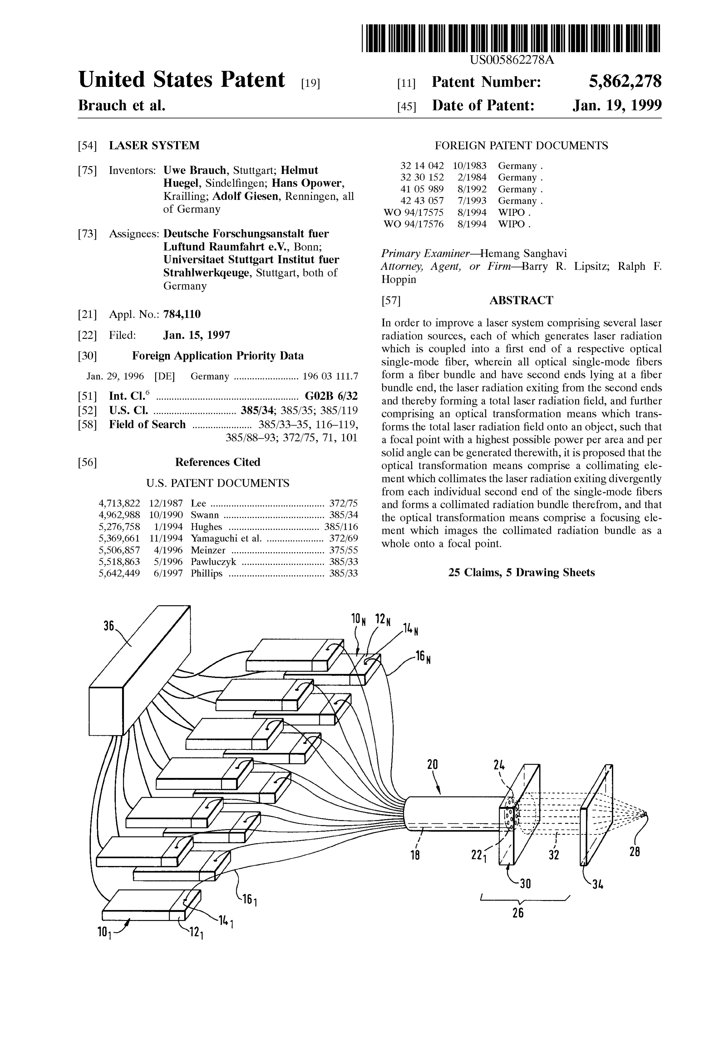
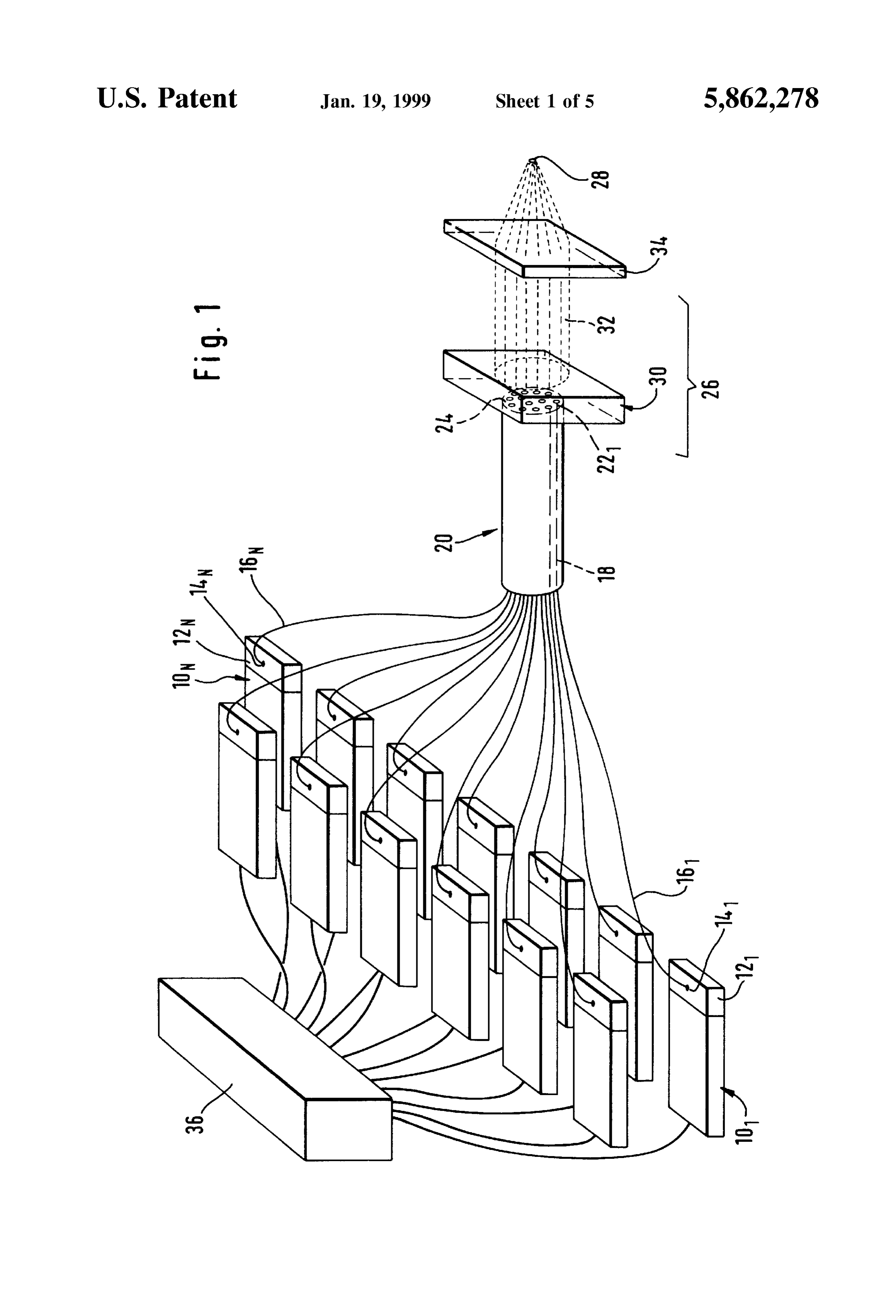
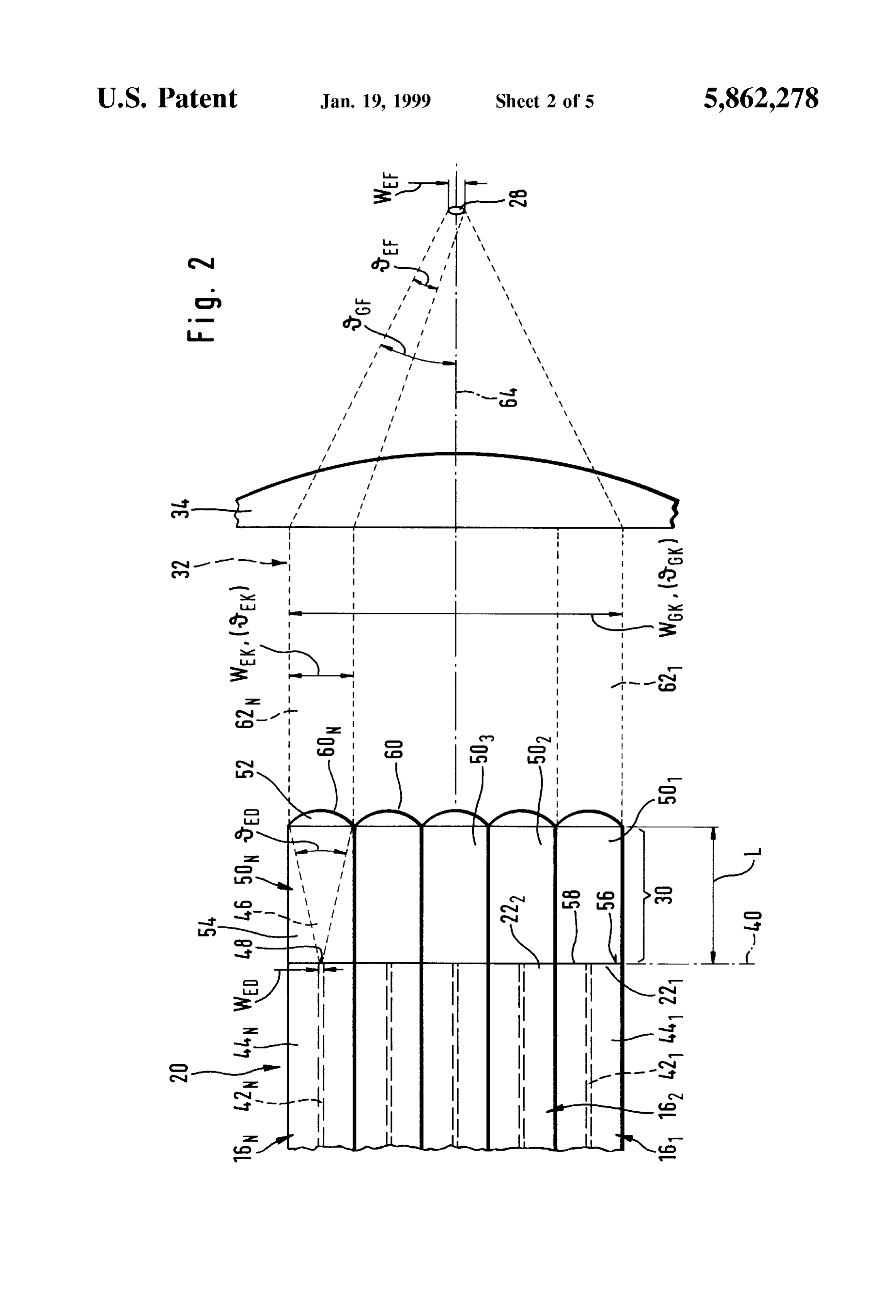
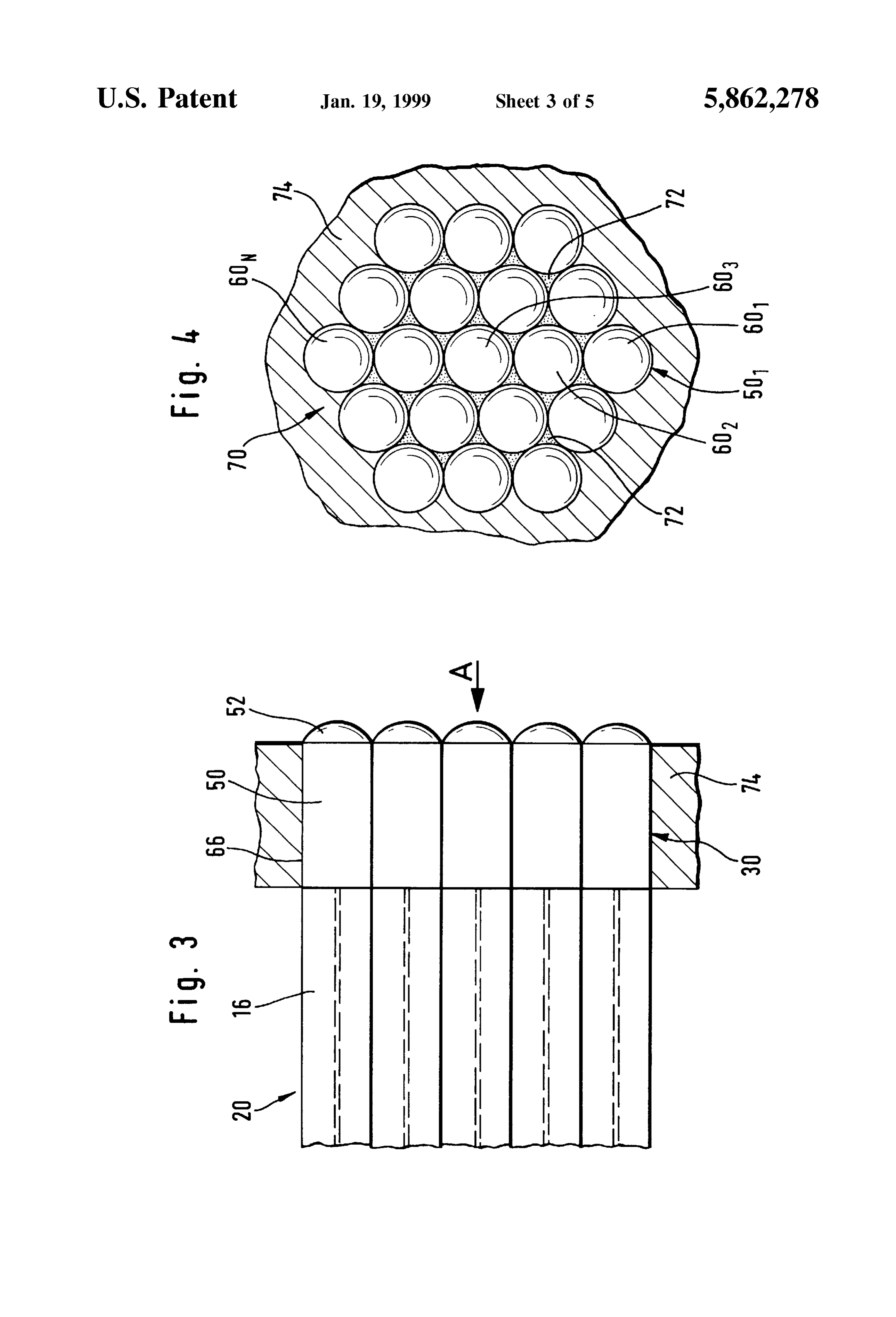
BRIEF DESCRIPTION OF THE DRAWINGS AS shown in part representation in FIG. 2, the Second ends FIG. 1 a Schematic representation of a laser System 22 of the single-mode fibers 16 preferably lie in the common according to the invention; plane 40 which is simultaneously the plane defined by the fiber bundle end 24.
FIG. 2 an optical transformation means according to the FIG. 2 also shows that each single-mode fiber 16 com invention with a first embodiment of a collimating element; prises a core 42 and a sheathing 44 Surrounding this core 42, FIG. 3 a representation of the first embodiment of the and the laser radiation is guided through the core 42 of the collimating element, Similar to FIG. 2, and a mechanical 35 single-mode fiber 16.
mounting thereof; Therefore, at the Second end 22 of the respective Single FIG. 4 a plan view in the direction of arrow A in FIG. 3 mode fiber 16, laser radiation exits in the form of a divergent with a part representation of the mounting of the collimating radiation cone 46 from each individual Surface 48 of each element; individual core 42.
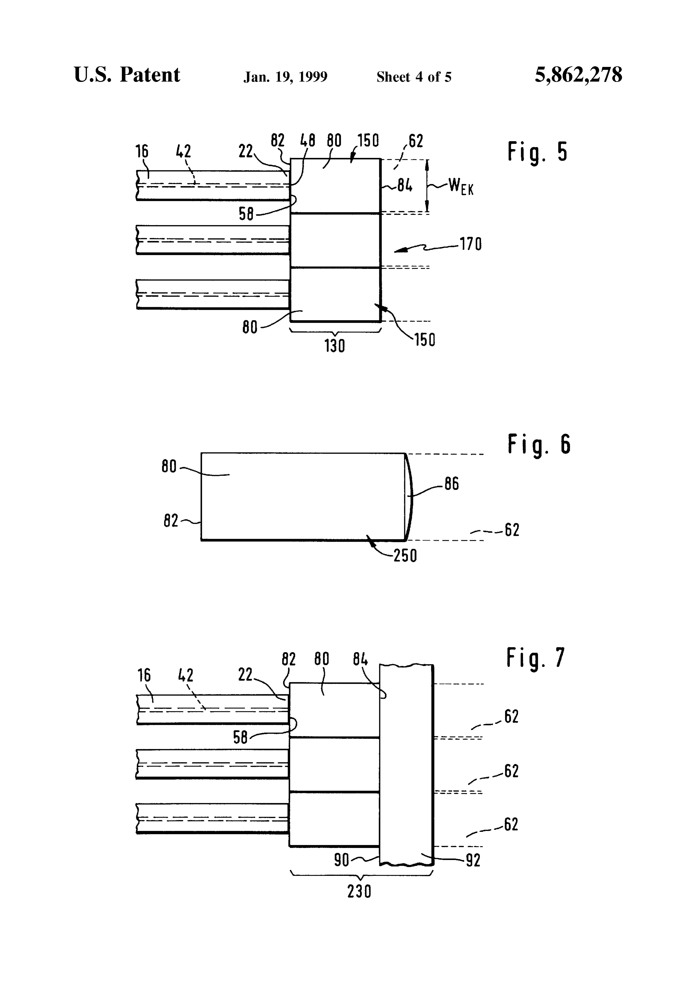
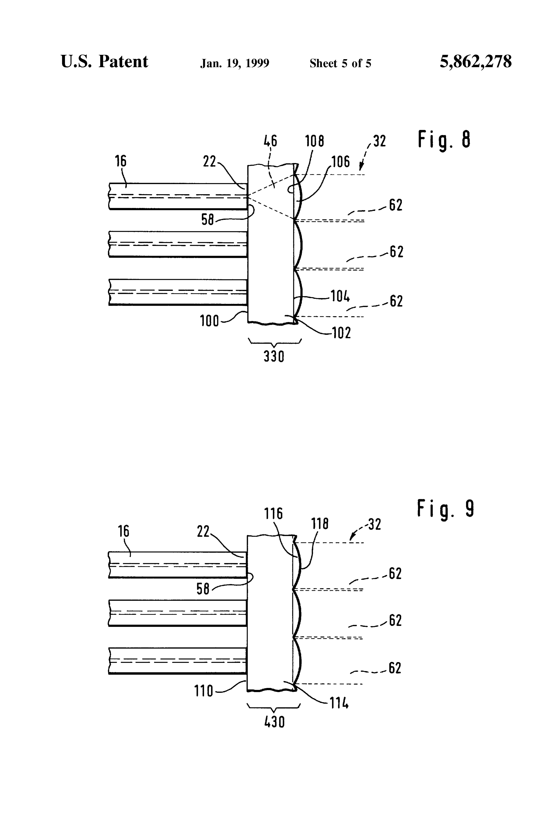
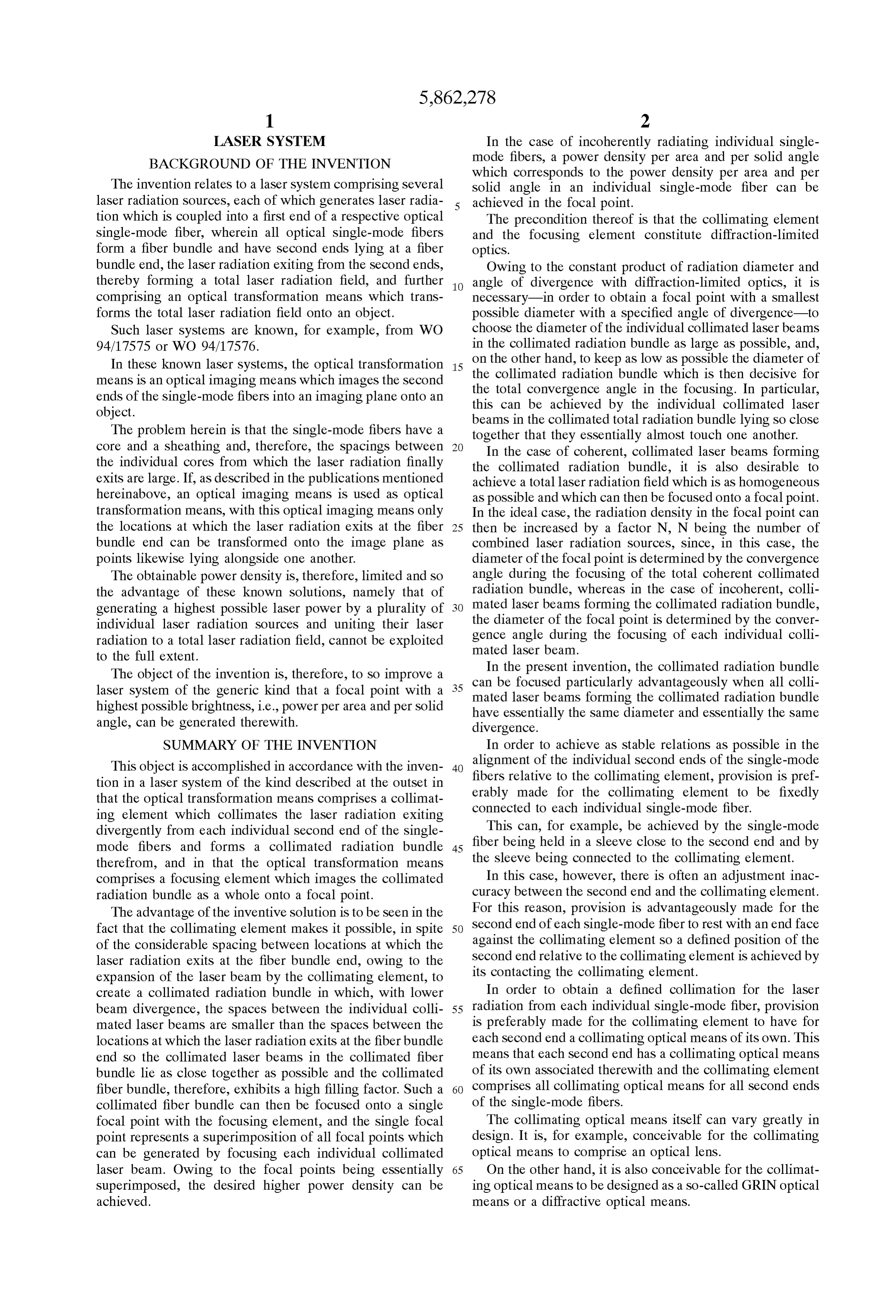
FIG. 5 a view, similar to FIG. 2, of a second embodiment 40 AS FIG. 2 also shows, a first embodiment of a collimating of the collimating element; element 30 comprises a plurality of Single optical elements FIG. 6 a Single representation of a variant of a Single 50 to 50, and each single optical element 50 comprises an optical element uSeable in the first or Second embodiment of optical lens 52 as collimating optical means. the collimating element; Each single optical element 50 is preferably made up of FIG. 7 a representation, similar to FIG. 2, of a third corresponds tofiber 45 a cylindrical piece 54 having a diameter which at least or is larger than the diameter of the Single embodiment of a collimating element; mode fiber 16. Such a cylindrical fiber piece 54 is placed at FIG. 8 a representation, similar to FIG. 2, of a fourth each end 22 of a single-mode fiber 16 in Such a way that its embodiment of a collimating element; end face 56 facing the Second end 22 of the Single-mode FIG. 9 a representation, similar to FIG. 2, of a fifth 50 fiber 16 rests essentially Surface-to-Surface against an end embodiment of a collimating element. face 58 of the respective single-mode fiber 16 forming the DETAILED DESCRIPTION OF THE Second end 22 and is optionally either welded or adhesively INVENTION bonded to the end 22 so that an essentially reflection-free optical contact exists between the material of the cylindrical
An embodiment of a laser System according to the 55 fiber piece 54 and the end face 48 of each core 42 so the laser invention, illustrated in FIG. 1, comprises a plurality of laser radiation passes essentially reflection-free from the core 42 radiation Sources 10 to 10 for example, a plurality of into the cylindrical fiber piece 54 and propagates in a Semiconductor lasers, each of which generates laser divergent manner therein in the form of the divergent radiation, which by means of a coupling unit 12 to 12, radiation cone 46.
each associated with an individual laser radiation Source 10, 60 In the case of the cylindrical fiber piece 54, the optical can be respectively coupled into a first end 14 of an optical lens 52 is formed preferably essentially integrally on the single-mode fiber 16. fiber piece 54 on the side opposite the end face 56 thereof so All of the single-mode fibers 16 lead away from the the cylindrical fiber piece 54 has a surface 60 curved individual coupling units 12 and form with their end regions approximately in the shape of a spherical cap on its side 18 remote from the first end 14 a fiber bundle, designated in 65 opposite the end face 56.
its entirety 20, and second ends 22 of the individual single A length L, which corresponds to a spacing of the optical mode fibers 16 together form a fiber bundle end 24. lens 52 from the end face 56, is selected Such that the
Page 10
divergent radiation cone 46, Starting from the end face 56, radiation is united by Single-mode fibers 16 being used, then has expanded to Such an extent on reaching the optical lens the power in the focal point 28 can be increased by approxi 52 that it attains approximately the diameter of the cylin mately the Same factor by which the product of Wis times drical fiber piece 54, and the optical lens 52 likewise having 0 increases when the individual collimated laser beams this diameter is thus capable of converting the laser radiation 62 to 62 lie as closely together as possible and essentially from the divergent radiation cone 46 into a collimated no spaces remain between them. For this reason, the Single individual laser beam 62, and the Sum of all collimated laser optical elements 50 are preferably arranged such that the beams 62 to 62 together forms the collimated radiation collimated laser beam 62 generated by each individual bundle 32. Single optical element 50 extends alongside, if possible, Each collimated laser beam 62 propagates as far as the touching, the next adjacent laser beam 62 in the collimated focusing element 34, which is, for example, a collecting lens radiation bundle 32.
detecting the entire collimated radiation bundle 32 and, However, this does not constitute a limitation for the therefore, focuses each individual collimated laser beam 62 diameter of the single optical elements 50. If it is chosen so to 62 onto the focal point 28, which, for reasons of as to be larger than that of the single-mode fibers 16, then the Simplicity, lies on an optical axis 64 representing an axis of 15 product Wis times 0 in the collimated radiation bundle symmetry of the collimated radiation bundle 32. 32 is still the same if the collimated laser beams 62 to 62. As the comparison in FIGS. 3 and 4 shows, the single lie as closely as possible alongside one another in the optical elements are arranged in the form of an extremely manner described hereinabove.
dense hexagonal package, with Outer circumferential Sur In a second embodiment of a collimating element 130, a faces 66 of the single optical elements 50 preferably lying so-called GRIN lens is respectively provided as single contiguously against one another and all of the Single optical optical element 150. The GRIN lens has a cylindrical body elements 50 to 50 forming a coherent unit 70 by the 80 within which the refractive index varies in the radial cylindrical fiber pieces 54 being bonded, for example, direction So the laser radiation is expanded and collimated in adhesively, to one another in the area of the Spaces 72 25 the GRIN lens. Such GRIN lenses, also called graded-index formed therebetween. rod lenses, are available, for example, from the Newport The entire unit 70 is then accommodated in a mounting 74 company, for example, in the form of a kit designated which is for precise mechanical positioning of the collimat F-GRK 1.
ing element 30 relative to the focusing element 34. The cylindrical body 80 has an end face 82 which faces AS an alternative to this, it is also possible to provide the single-mode fiber 16 and with which it rests directly cylindrical fiber pieces 54 with a hexagonal outer contour against the end face 58 of the respective end 22 so an instead of the circular-cylindrical outer circumferential Sur essentially reflection-free transition of the laser radiation faces 66, So that on account of their croSS Section, the from the end surface 48 of the core 42 into the cylindrical cylindrical fiber pieces 54 can lie Surface-to-Surface against body 80 of the GRIN lens is possible. Furthermore, the one another in the form of a regular hexagon and their 35 cylindrical body 80 also has opposite the end face 82 an end Surfaces can, for example, be adhesively bonded to one face 84 from which the respective collimated laser beam 62 another. exits in expanded form. The GRIN lenses are also of such The advantage of the Single optical elements 50 lying dimensions that the diameter W of the collimated laser close together is that the collimated laser beams 62 to 62 beam 62 corresponds essentially to the diameter of the in the collimated radiation bundle 32 also lie almost con 40 cylindrical body 80 in order to likewise avoid spaces tiguously against one another and, therefore, a total croSS between individual collimated laser beams 62. Sectional area of the collimated radiation bundle 32 deter Furthermore, all cylindrical bodies 80 form a coherent mining the total beam diameter W is insignificantly larger unit 170 which is held in a mounting in the same way as than the Sum of all cross-sectional areas of all collimated illustrated in the first embodiment of the collimating element laser beams 62 to 62 with the diameter W. 45 30.
Furthermore, both the collimating element 30 and the As illustrated in FIG. 6, it is, however, also possible, with focusing element 34 are designed Such that they form a single optical means 250, to provide a GRIN lens in the diffraction-limited optics So the laws of Gaussian optics cylindrical body 80, but to provide an additional optical lens apply. As a result of this, the product of beam diameter W. 86 on the side of the body 80 opposite the end face 82 so that times angle of divergence 0 is always a constant and at best 50 the combined effect of the GRIN lens formed by the cylin can be maintained by the respective optical elements. drical body 80 and the additional optical lens 86 generates If the laser radiation of a single laser radiation Source the collimated laser beam 62. Herein, lens errors can be exiting from the end surface 48 of each individual core 42 advantageously compensated by the optical lens 86 in com is considered, it then applies for the divergent radiation cone bination with the GRIN lens effect in the cylindrical body 46 that the angle of divergence 0 multiplied by the 55 80.
diameter W of the end Surface 48 is equal to the product In a further embodiment of an inventive collimating of the diameter W of the collimated laser beam 62 times element 230, illustrated in FIG. 7, a GRIN lens described the angle of divergence 0 and is equal to the product of the hereinabove and provided in the cylindrical body 80 adjoins diameter of the focal point W times the convergence angle the end face 58 of each end 22 of each single-mode fiber 16, Oer. 60 and the cylindrical bodies 80 of the GRIN lenses are not Furthermore, the product of the diameter of the focal point joined to one another at their circumferences but are Seated W, and the convergence angle 0 for the total radiation with their end face 84 on a surface 90 of a carrier plate 92 converging towards the focal point is equal to the product of and are firmly connected thereto. The carrier plate 92 the diameter W of the collimated radiation bundle 32 constitutes a common Stabilizing element for all cylindrical times the angle of divergence 0 thereof. If the power 65 bodies 80 of the GRIN lenses and thus fixes these and, in available in the focal point 28 is to be increased by a largest addition, via the GRIN lenses, the ends 22 of the individual possible number of laser radiation sources 10 whose laser single-mode fibers 16 contacting the end faces 82 of the
Page 11
GRIN lenses. With this carrier plate 92, for example, the 2. A laser System as defined in claim 1, wherein: collimating element 230 can then be mechanically posi all laser beams forming Said collimated radiation bundle tioned exactly relative to the focusing element 34 in a simple have essentially the same diameter (W) and essen way. tially the same divergence (0). In a further embodiment, illustrated in FIG. 8, the single 3. A laser System as defined in claim 1, wherein: mode fibers 16 directly contact a surface 100 of a carrier Said collimating optical means comprises an optical lens. plate 102 with their end faces 58 and are exactly positioned 4. A laser System as defined in claim 1, wherein: by the surface 100 of the carrier plate 102 and fixed on the Said collimating optical means comprises a GRIN optical carrier plate 102. The carrier plate 102 thus allows fixing of means or a diffractive optical means. the ends 22 of all Single-mode fibers in a defined manner 1O 5. A laser System as defined in claim 1, wherein: relative to one another and also relative to the collimating Said collimating optical means comprises a combined element 330. The collimating element 330 is formed not optical means comprising of at least one of an optical only by the carrier plate 102 but also by optical lenses 106 lens, a GRIN optical means, and a diffractive optical seated on this carrier plate 102 on a surface 104 opposite the CS.
surface 100. The optical lenses 106 have a plane base surface 15 6. A laser System as defined in claim 1, wherein: 108 with which they are joined in an essentially reflection Said collimating optical means generates a collimated free manner to the carrier plate 102 on the surface 104 laser beam, the diameter (W) of which corresponds thereof. essentially to an outer diameter of Said respective The spacing between the surfaces 100 and 104 of the collimating optical means.
carrier plate 102 is Selected Such that the divergent radiation 7. A laser System as defined in claim 1, wherein: cone 46 expands in the carrier plate 102 to the extent that its each collimating optical means comprises a single optical diameter corresponds to the diameter of the plane Surface element.
108 of the optical lens 106 so the optical lens 106 is, in turn, 8. A laser system as defined in claim 7, wherein: able to generate collimated laser beams 62 extending in the Said Single optical elements rest against one another in the collimated radiation bundle 32 and thereby essentially 25 area of their outer contour. touching one another. 9. A laser system as defined in claim 7, wherein: In a further embodiment of a collimating element 430, Said Single optical elements are arranged in a highly illustrated in FIG. 9, the carrier plate 114 is provided on one dense, hexagonal package in one plane. side thereof with a plane surface 110 which the ends 22 of 10. A laser System, comprising: all single-mode fibers 16 contact with their end faces 58 and Several laser radiation Sources, each of which generates on which they are fixed, for example, with adhesive, while laser radiation which is coupled into a first end of a a surface opposite the surface 110 has areas 116 with respective Single-mode optical fiber, spherical-cap-shaped Surfaces 118 so the areas 116 act in the Said respective Single-mode optical fibers forming a fiber Same way as the optical lenses 106, but are an integral bundle and having Second ends lying at a fiber bundle component of the carrier plate 114. 35 end, laid laser radiation exiting from Said Second ends
If, taking into consideration the index of refraction, the and thereby forming a total laser radiation field, and lens-shaped areas 116 and the curvatures of the Spherical an optical transformation means which transforms the cap-shaped Surface areas 118 are designed as in the embodi total laser radiation field onto an object, wherein: ment according to FIG. 8, collimated laser beams 62 which Said optical transformation means comprises a colli essentially touch one another in the collimated radiation 40 mating element which collimates Said laser radiation bundle 32 can Similarly be generated. exiting divergently from each individual Second end What is claimed is:
1. A laser System, comprising: of Said Single-mode fibers and forms a collimated radiation bundle therefrom,
Several laser radiation Sources, each of which generates 45 Said Second ends of Said optical Single-mode fibers rest laser radiation which is coupled into a first end of a with an end face against Said collimating element, respective Single-mode optical fiber, Said collimating element comprises a carrier, Said respective Single-mode optical fibers forming a fiber Said carrier comprises a one-piece, light-permeable bundle and having Second ends lying at a fiber bundle plate, end, Said laser radiation exiting from Said Second ends 50 Said collimating element comprises a different colli and thereby forming a total laser radiation field, and mating optical means for the Second end of each an optical transformation means which transforms the Single-mode fiber, total laser radiation field onto an object, wherein: a transition from Said collimating optical means to Said Said optical transformation means comprises a collimat carrier occurs in an essentially reflection-free ing element which collimates Said laser radiation exit 55 manner, and ing divergently from each individual Second end of Said Said optical transformation means further comprises a Single-mode fibers and forms a collimated radiation focusing element which imageS Said collimated bundle therefrom, radiation bundle as a whole onto a focal point. Said collimating element comprises a different collimating 11. A laser system as defined in claim 10, wherein: optical means for the Second end of each Single-mode 60 Said collimating element is fixedly connected to each fiber, individual Single-mode fiber.
each of Said collimating optical means is formed by 12. A laser system as defined in claim 10, wherein: continuation of the Single-mode fiber without a core, Said Second ends of Said Single-mode fiberS rest with their and end face against Said carrier means. Said optical transformation means further comprises a 65 13. A laser system as defined in claim 10, wherein: focusing element which imageS Said collimated radia Said Second ends of Said Single-mode fiberS rest with their tion bundle as a whole onto a focal point. end faces against an end face of Said Single optical
Page 12
elements, and Said Single optical elements rest with the Said respective Single-mode optical fibers forming a fiber other end face against Said carrier means. bundle and having Second ends lying at a fiber bundle 14. A laser system as defined in claim 10, wherein: end, Said laser radiation exiting from Said Second ends Said collimating element is of one-piece design and forms and thereby forming a total laser radiation field, and for each Second end a collimating optical means of its an optical transformation means which transforms the
total laser radiation field onto an object, wherein:
15. A laser system as defined in claim 10, wherein: Said optical transformation means comprises a collimat Said carrier means extends over an entire croSS Section of
Said collimated radiation bundle. ing element which collimates Said laser radiation exit ing divergently from each individual Second end of Said 16. A laser system as defined in claim 15, wherein: Single-mode fibers and forms a collimated radiation Said one-piece, light-permeable plate positions said Single bundle therefrom, optical elements in a defined manner relative to one Said collimating element is formed by a lens array, another.
wherein Said lens array comprises an individual lens 17. A laser system as defined in claim 16, wherein: 15 for each Second end of Said optical Single-mode fiber, Said Single optical elements rest with their end face which individually collimates Said laser radiation against Said carrier means. exiting divergently from each individual Second end, 18. A laser system as defined in claim 16, wherein: Said lens array is arranged on a carrier, Said carrier means carries Said Single optical elements. Said carrier comprises a one-piece, light-permeable 19. A laser system as defined in claim 10, wherein: plate,
Said collimating element is formed by a plurality of Single the transition from Said fiberbundle to Said plate occurs optical elements connected to one another. in an essentially reflection-free manner, and 20. A laser system as defined in claim 19, wherein: Said optical transformation means further comprises a Said Single optical elements are connected to one another 25 focusing element which imageS Said collimated in the area of their outer contour. radiation bundle as a whole onto a focal point. 21. A laser system as defined in claim 19, wherein: 24. A laser System as defined in claim 23, wherein: Said Second ends of Said Single-mode fiberS rest with their Said Second end of each Single-mode fiber rests with an end faces against an end face of Said Single optical end face against Said collimating element. elements. 25. A laser System, comprising: 22. A laser System, comprising:
Several laser radiation Sources, each of which generates Several laser radiation Sources, each of which generates laser radiation which is coupled into a first end of a laser radiation which is coupled into a first end of a respective Single-mode optical fiber, respective single-mode optical fiber, Said respective Single-mode optical fibers forming a fiber 35 Said respective Single-mode optical fibers forming a fiber bundle and having Second ends lying at a fiber bundle bundle and having Second ends lying at a fiber bundle end, Said laser radiation exiting from Said Second ends end, Said laser radiation exiting from Said Second ends and thereby forming a total laser radiation field, and and thereby forming a total laser radiation field, and an optical transformation means which transforms the an optical transformation means which transforms the total laser radiation field onto an object, wherein: 40 total laser radiation field onto an object, wherein: Said optical transformation means comprises a colli Said optical transformation means comprises a colli mating element which collimates Said laser radiation mating element which collimates Said laser radiation exiting divergently from each individual Second end exiting divergently from each individual Second end of Said Single-mode fibers and forms a collimated of Said Single-mode fibers and forms a collimated
radiation bundle therefrom,
Said collimating element is formed by a lens array Said collimating element is formed by a lens array, having a plurality of lenses, said lens array comprises an individual GRIN lens each of Said lenses is formed by continuation of the combined with an optical diffractive lens for each Single-mode fiber without a core, Second end of Said optical Single-mode fiber, which each of Said lenses comprising at least one of a GRIN 50 individually collimates Said laser radiation exiting lens and a diffractive optical lens resulting in an divergently from each individual Second end, essentially reflection-free transition of the radiation Said lens array is arranged on a carrier, occurring from the Single-mode fiber to the lenses, Said carrier comprises a one-piece, light-permeable and plate,
Said optical transformation means further comprises a 55 the transition from Said fiberbundle to Said plate occurs focusing element which imageS Said collimated in an essentially reflection-free manner, and radiation bundle as a whole onto a focal point. Said optical transformation means further comprises a 23. A laser System, comprising: focusing element which imageS Said collimated Several laser radiation Sources, each of which generates 60 radiation bundle as a whole onto a focal point. laser radiation which is coupled into a first end of a respective Single-mode optical fiber, k k k k k
Provenance
- Collection
- Cited prior art
- Original PDF
- patentimages.storage.googleapis.com →
- Filed
- 1997-01-15
- Pages
- 12
- Method
- pdftotext (the PDF's own text layer) + pdftoppm 300dpi page scans
- Source
- Google Patents bibliographic record
- Granted
- 1999-01-19
- Inventors
- Uwe Brauch; Helmut Huegel; Hans Opower; Adolf Giesen; Institut fuer Strahlwerkzeuge Universitaet Stuttgart; Deutsches Zentrum fuer Luft und Raumfahrt eV
- Transcribed from
- patentimages.storage.googleapis.com →