(250)
Booster coil-Assembly
Also written fluid mixing chamber · Electrical Circuit · coil-wrap
Where it is first named
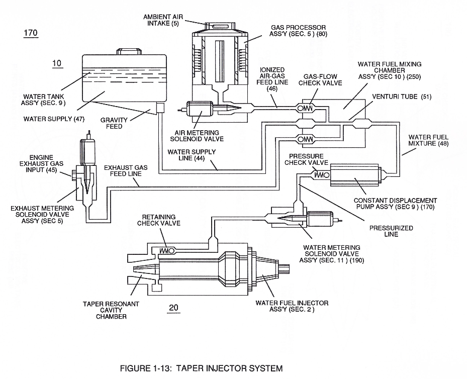
In like manner, water supply (10) of Figure (170), non-combustible gases (45) (Engine Exhaust gases), and ambient air ionized gases (46) (air gases having missing electrons) are uniformly intermixed when moving into, passing through and beyond fluid mixing chamber (250) of Figure (13) by way of venturi tube-cavity (51)...
How it is written
- (250) 4×
Drawings 17
-
(240) of Figure (3-31) · Gas Processor
-
Figure (3-2) · Laser Distributor
-
Carries this number · WFC 422DA - Illustrations
-
Carries this number · Voltage Intensifier Coil Assembly
-
Carries this number · Voltage Intensifier Coil Assembly
-
Carries this number · Differential Air-Gas Inlet Control
-
Carries this number · Differential Air-Gas Inlet Control
-
Carries this number · Differential Air-Gas Inlet Control
-
(170) of Figure (13) · Water Fuel Injector (Taper Resonant Cavity Chamber)
-
(170) of Figure (13) · Water Fuel Injector (Taper Resonant Cavity Chamber)
-
Fluid Displacement Pump (170) of Figure (13) · Water Fuel Injector (Taper Resonant Cavity Chamber)
-
2-3 Water Inlet Housing · Water Fuel Injector Illustrations
-
2-6 Ceramic Insert · Water Fuel Injector Illustrations
-
Carries this number · Steam Resonator Assembly
-
Carries this number · Steam Resonator Assembly
-
Carries this number · Steam Resonator Assembly
-
Carries this number · Steam Resonator Assembly
Where it is named · 4
Water Fuel Injector (Taper Resonant Cavity Chamber) 1×
-
fluid mixing chamber (250)
In like manner, water supply (10) of Figure (170), non-combustible gases (45) (Engine Exhaust gases), and ambient air ionized gases (46) (air gases having missing electrons) are uniformly intermixed when moving into, passing through and beyond fluid mixing chamber (250) of Figure (13) by way of venturi tube-cavity (51)...
Funneling Effect 3×
-
Booster coil-Assembly (250)
… ty (VL ~ Vn ~ Vm) to higher magnitude of "Electrical Force" (Vma xxx Vmn) which is due to the inductance/capacitance values of each succeeding coil-structure (61a x 61n) forming Booster coil-Assembly (250), as illustrated in (240) of Figure (20).
-
coil-wrap (250)
… Voltage Intensity (xxx Vmn) to Secondary Voltage Level (71), once again, inductance core-slug (73) (magnetic core material) advances (via solenoid Control 74) toward, passes through inside coil-wrap (250) in linear manner to "Switch-Off" each adjacent coil-stage (61a xxx 61n) by "Shunting" or "Redirecting" induced voltage intensity (Vmn xxx Vma) to its respective electrical out-put leads (72n - 72c - …
-
Electrical Circuit (250)
… is switch-off by Electronic Switch Circuit (79), Voltage Intensity (VL ~ Vn xxx) is increased due to inductance / capacitance of Voltage Expander Coil (78a) which is, now, added to Electrical Circuit (250) by electrical pathway (82a) since electromagnetic coupling field (76b) prevents electron flow to cause open circuit (82b)...