patent · US4476395
Tandem-generator design for aircraft
9 October 1984
Page 1 — bibliographic record
United States Patent (19) 11) Patent Number: 4,476,395 Cronin 45) Date of Patent: Oct. 9, 1984 54, TANDEM-GENERATOR DESIGN FOR Primary Examiner-S. J. Witkowski AIRCRAFT Assistant Examiner-Shelley Wade 75) Inventor: Michael J. Cronin, Sherman Oaks, Attorney, Agent, or Firm-Louis L. Dachs Calif. 57) ABSTRACT (73) Assignee: Lockheed Corporation, Burbank, The invention is an aircraft power generation system Calif.
which includes a tandem generator (10) which includes (21) Appl. No.: 312,783 left and right generators (14, 15) arranged within a 22 Filed: Oct. 19, 1981 single housing (12). The left and right generators (14, 15) are driven at the anti-drive end of the tandem gener 51 Int. Cl. ............................................. H02K 7/116 ator (10) by a gear arrangement including gears (22), 52 U.S. Cl. ....................................... 290/6; 290/4 C; (24) and (26). A phase indexer (36) including a phase 310/59; 310/83; 310/112 adjust nut (38) is arranged in conjunction with driven 58) Field of Search ............... 310/112, 59, 83; 290/6, gear (26) to provide for "vernier' phase-alignment of 290/4A, 4 C the generator rotors. In an alternative embodiment, 56) References Cited phase-alignment of the generator rotors is accomplished
by arranging them in-line to form an in-line tandem generator (10).
653,088 7/1900 Hutin et al. . In a preferred arrangement, an in-line generator (70) is 907, 176 12/1908 Richardson . arranged to be isolated from an aircraft engine via an
2,085,275 6/1937 Schmidt .............................. 310/112 electromechanical disconnect (108). The disconnect 2,153,386 4/1939 Morey ................................... 310/59 (108) includes a pin (130) activated by a solenoid (110), 3,463,954 8/1969 Latta ..................................... 310/90 which upon receipt of a disconnect command or signal, 3,651,355 3/1972 Mason .............. ... 310/12 pulls the pin (130) from a hole (131) in ring gear (114) 3,717,780 2/1973 Hohne, Jr. etal ... 310/112 thereby disconnecting the tandem generator (70). 3,836,802 9/1974 Parker .............. ... 310/154 4,323,803 4/1982 Danko et al. ......................... 310/59 2 Claims, 16 Drawing Figures
Air
ENN a NunN
NSS a SK.
ZZZZZZZ, 7
Lyng. IIS
Page 2
Drawing sheet — no readable text.
Page 3
Drawing sheet — no readable text.
Page 4
Drawing sheet — no readable text.
Page 5
Drawing sheet — no readable text.
Page 6
Drawing sheet — no readable text.
Page 7
TANDEM-GENERATOR DESIGN FOR AIRCRAFT identical machines to permit separate or paralleled op eration.
TECHNICAL FIELD None of the aforementioned prior art approaches to power generation provide either a dual-redundancy of
The invention relates generally to aircraft power electric power in a single-powerplant, simultaneously generation systems, and in particular to a tandem gener providing integrated-cooling and a common mechani ator design particularly useful in single and multi cal interface with an aircraft engine drive, or a rapid engined aircraft. The power generation system includes and effective disconnect device for disconnecting such an electromechanical disconnect device which isolates powerplants to prevent energy overloads. the generator in the event of a fault, and which is lo 10 In view of the inherent limitations and problems asso cated in the power take-off (PTO) shaft on the en ciated with aircraft applications and the above prior art
approaches, there is a need to provide an aircraft power
BACKGROUND ART generation system that is utilizable and highly desirable In many aircraft systems a single drive source may 15 where the number of available drive sources may be only be available, but dual-redundancy in the generat limited. Such a power generation system should ideally ing system may be required for power integrity and be capable of alleviating several problems associated reliability. Similarly, a four-generator power source with known aircraft-single generator arrangements; may be necessary in a two-engine airplane. namely, that such single generators, unless oversized, In addition to the limitation of available drive sources 20 are often incapable of starting an engine, require addi in aircraft, there is also the problem that a single genera tional mount-pads, additional drive-provisions, addi tor, unless oversized, may well be incapable of starting tional mechanical-interfaces, additional cooling-inter an engine. Where such a starting capability is desired, faces, and additional hydraulic-lines/heat exchangers. there is a need for a power generation system utilizing a From the foregoing it can be seen that it is a primary machine arrangement which will overcome this prob 25 object of this invention to provide a novel aircraft lem. Finally, use of a plurality of conventional single power generation system which includes a dual AC generators would require additional mount-pads, drive generator arrangement within a single housing. The provisions, mechanical-interfaces, cooling-interfaces, generators are adapted to be driven by a single aircraft and hydraulic-lines/heat exchangers. drive source to provide dual-redundancy in the aircraft Various tandem arrangements of electric machines 30 power generation system for power integrity and reli are know. One such system, shown in U.S. Pat. No. ability.
1,874,094 to Ford et al, discloses two AC machines with It is also an object of this invention to provide an separate magnetic field systems in a single enclosure to aircraft "dual-generator' configuration in a single "tan form an electric transmission system. Several other U.S. dem-generator' housing which utilizes one drive patents, namely U.S. Pat. Nos. 907, 176 to Richardson, 35 power source, one mechanical-interface, and one cool 3,463,954 to Latta, 3,651,355 to Mason, and 3,717,780 to ing medium.
Hohne, Jr. et al, show multi-armature motors arranged A still further object of the present invention is to in a single housing. provide a tandem-generator power system which im One progressive early approach to a dual machine proves source reliability of an aircraft electrical power excitation method for alternators is disclosed in U.S. 40
Pat. No. 653,088 to Hutin et al. In this patent, an in-line system that has a high priority placed upon the loads. assembly of two machines on one shaft is shown, with vide Yet another object of the present invention is to pro the integrated machine incorporating multiple wind a power generation system having a duality of ings, including a "compensating' winding which neu power supply from a single engine driven source that can be mounted as a single entity on an aircraft engine tralizes the effects of flux-distortion caused by armature 45 pad, reaction. The machine provides an excitation and volt fluid and that can have a single interface with a cooling age-regulation means which permits the AC generator supply.
to supply varying loads, and loads with different power A still further object of the present invention is to factors. provide a fast-acting mechanical shaft-disconnect con The '088 invention was a precursor of more modern 50 trol that can isolate an aircraft engine from a remote aircraft-type generators, where a DC exciter is mounted driven accessory to protect it against mechanical-sei on the same shaft as the field of the alternator (AC zures and other problems.
generator). In these machines, the armature (AC wind DISCLOSURE OF INVENTION ing) of the exciter is carried on the rotor and its AC output is rectified by diodes, also mounted on the rotor. 55 The invention relates to a tandem generator arrange The rectified AC output of the exciter is then applied to ment for aircraft wherein two electrically separate three the field of the alternator. Regulation of the output AC phase AC windings and two rotating fields are arranged voltage in these machines is effected by current-changes in a single housing. The generators are arranged to be in the DC (stator) winding of the exciter. driven by a single aircraft drive source and require only The '088 and later machines, while using more than 60 a single mount pad and cooling medium. In a first em one electric machine in a single housing and mounting bodiment, the two generators are arranged within the more than one rotor winding on a common shaft, never single housing in a "side-by-side' relationship, while in theless do not recognize, disclose or address the initial a second embodiment the generators are arranged "in start, power generation, mounting, cooling and discon line' within the housing.
nect problems associated with aircraft and solved by the 65 A second aspect of the invention includes an electro present invention. These problems have been recog mechanical nized and solved herein by mounting and mechanically craft engine disconnect between the located in proximity to the air engine and the tandem genera and electrically phase-aligning and electro-magnetically tor arrangement. The disconnect, upon receiving a sig
Page 8
nal indicating an overload, overheat, etc., condition, of separate outputs is possible without attendant problems activates via a solenoid to isolate the tandem generator. arespeed and phase synchronization. Where the outputs of different KVA capacity, one generator may be
The novel features which are believed to be charac used as a "normal' power source and the other, lower teristic of the invention, both as to its organization and capacity its method of operation, together with further objects 5 output, could be used as an "emergency' and advantages thereof, will be better understood from power source.
The tandem generator of the present invention can be the following description, taken in connection with the designed for an "in-line' or "side-by-side' configura accompanying drawings in which a presently preferred embodiment of the invention is illustrated by way of tion. The "side-by-side' tandem generator configura example. It is to be expressly understood, however, that 10 tion shown in FIGS. 1-4 demands special consideration the drawings are for purposes of illustration and de with regard to mechanical and electrical phase-align scription only, and are not intended as a definition of the ment. In an "in-line' tandem generator design, as shown limits of the invention. in FIG. 5, it is possible to insure a precise mechanical phase alignment between the two generators in a simple
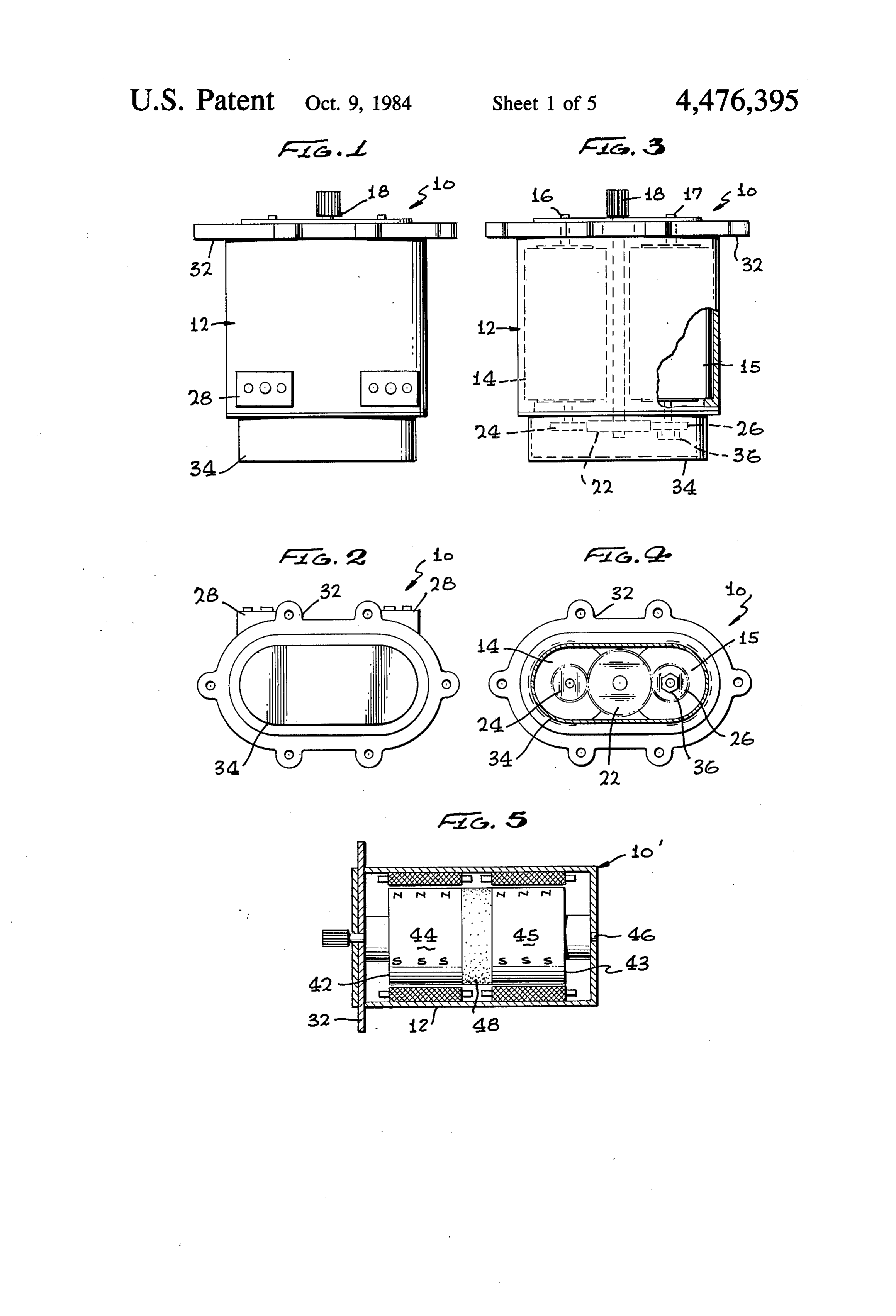
DESCRIPTION OF DRAWINGS 15 manner. This mechanical phase-alignment is necessary FIG. 1 is a plan view of a "side-by-side' tandem since generators cannot be paralleled unless the electri cal phase angle between the generators are closely con generator in accordance with the present invention; trolled.
FIG. 2 is an end view of the anti-drive end of the tandem generator of FIG. 1; In accordance with a first embodiment of the present FIG. 3 is a plan view, partially broken away, of the 20 invention,
as shown in FIGS. 1-4, a tandem generator provided having left and right generators (14) tandem generator of FIG. 1;
FIG. 4 is an end plan view of the tandem generator of and (15) enclosed by a single housing (12). The cylindri cal stators of generators (14) and (15) may be press fitted
FIG. 1 with the gear drive cover removed;
FIG. 5 is a diagramatic cross-sectional view of an or otherwise secured within two cylindrical cavities in "in-line' tandem generator in accordance with another 25 the housing (12). As can be seen by reference to FIGS. embodiment of the present invention; 1 and 3, both generators (14) and (15) can be cooled by FIGS. 6-9 are electrical schematics showing various a single fluid cooling loop, via a fluid inlet (16) and a switching systems for handling the power outputs of the return outlet (17). Any suitable coolant, such as oil or two generators of the FIG. 1 and 5 tandem generators; coolanol (ethylene glycol, etc.) or the like can be used. FIG. 10 is a diagramatic view of an aircraft engine, 30 As shown in FIGS. 3 and 4, an input drive shaft (18) "in-line' tanden generator, and an electro-mechanical is carried through the housing (12) and is arranged to disconnect power generation system in accordance drive generators (14) and (15) via interaction of a with another aspect of the present invention; "drive" gear (22) with left generator "driven" gear (24) FIG. 11 is an enlarged cross-sectional view partly and right generator "driven' gear (26), Gears (22), (24) broken away of the electromechanical disconnect of 35 and (26) are all positioned at the "anti-drive' end of the FIG. 10; machine (10). Positioning of these gears at the "anti FIG. 12 is a cross-sectional view taken on line 12-12 drive' end has three primary advantages: (1) gear of FIG. 11; meshing can be accomplished while the tandem genera FIG. 13 is a diagramatic view of an aircraft engine tor is mounted on the engine pad; (2) phase alignment of showing accessory machines driven by the engine via 40 the generator rotors can be accomplished at the "anti an electromechanical disconnect/transmission in accor drive' end; and (3) a speed increase (or decrease) can be dance with another embodiment of the present inven dependence effected within the generator housing (12), removing tion; of the generator rotor speed on the engine FIG. 14 is a schematic view of an electromechanical drive shaft speed.
disconnect/speed-changer in accordance with the pres 45 Referring again to FIGS. 1-4, the tandem generator ent invention interposed between an aircraft engine and (10) is shown to include dual three-phase output termi nal blocks (28) and a mounting flange (32). The drive a generator; and
FIG. 15 is a diagramatic view of the electrome gear (22) and driven gears (24), (26) are enclosed at the chanical/speed-changer of FIG. 14. In the various anti-drive end of the tandem generator (10) by a gear drawing Figures, like numerals denote like parts. 50 cover (34). A mechanical phase indexer (36) including a phase adjust nut (38) associated with the, right genera
BEST MODE OF CARRYING OUT THE tor (15) is utilized to carry out “vernier' phase-align INVENTION ment of the generator rotors. As a means to enable
In many aircraft, two (or even one) engines may be alignment of the generator rotors, the driven gears (24), the only propulsion power-sources in the aircraft, but 55 (26) are located on "master" splines on the rotor shafts the dependence on electrics may be such that a multiple of the two generators. When this "course-alignment' is generator system is necessary. For example, in a two effected, "vernier" phase-alignment can be accom engined aircraft, it would be possible to provide a four plished by the indexer phase adjust nut (38), when the channel generator system, by utilization of two tandem gears (24), (26) are meshed with the drive gear (22). generators. From a reliability standpoint, this would be 60 This phase adjustment coupling is available industrially very desirable in an aircraft which might utilize electric from the Harmonic Drive Division of USM Corpora power for the primary and secondary flight control tion under the name "infinite-indexer'; its operational systems, and other important services. principle is based upon "harmonic-drive' concepts. A In accordance with one preferred embodiment of the turn of one flat of 60 on the indexer phase adjust nut present invention, two electrically and physically sepa 65 (38) effects an arc-change of less than 0.6 (36 minutes). rate three-phase AC generators are cooperatively Such alignments can thus be made on the tandem gener mounted in a single housing. When the electrical de ator of the drive source or, more appropriately, when it signs of both generators are identical, paralleling of the is mounted on the drive source. In the latter case, the
Page 9
adjustment can also be effected dynamically while the (i) If the stator windings are connected as in FIG. 7A, time mover is running, using an oscilloscope to moni the 200 V/800 Hz would be unsuitable for AC tor the actual electrical phase-alignment conditions. (induction) motor loads, if the loads were designed A second embodiment of the present invention in the for 400 V/800 Hz operation. form of an "in-line' tandem generator (10) is shown in 5 (ii) The FIG. 7B winding-configuration could not be FIG. 5, and consists of two generators (42), (43) having used if the loads were designed for 200V/800 Hz their respective rotors (44), (45) mounted upon a single operation.
drive shaft (46). The rotors (44), (45) are shown sepa (iii) Conventional 200V/400 Hz power could not be rated by a non-magnetic material (48) which inhibits applied, either to the generator as a starter, or to flux-induced voltages in the winding overhangs. With 10 supply aircraft loads, if they were designed for 200 this particular arrangement, the phase alignment re V/800 Hz operation.
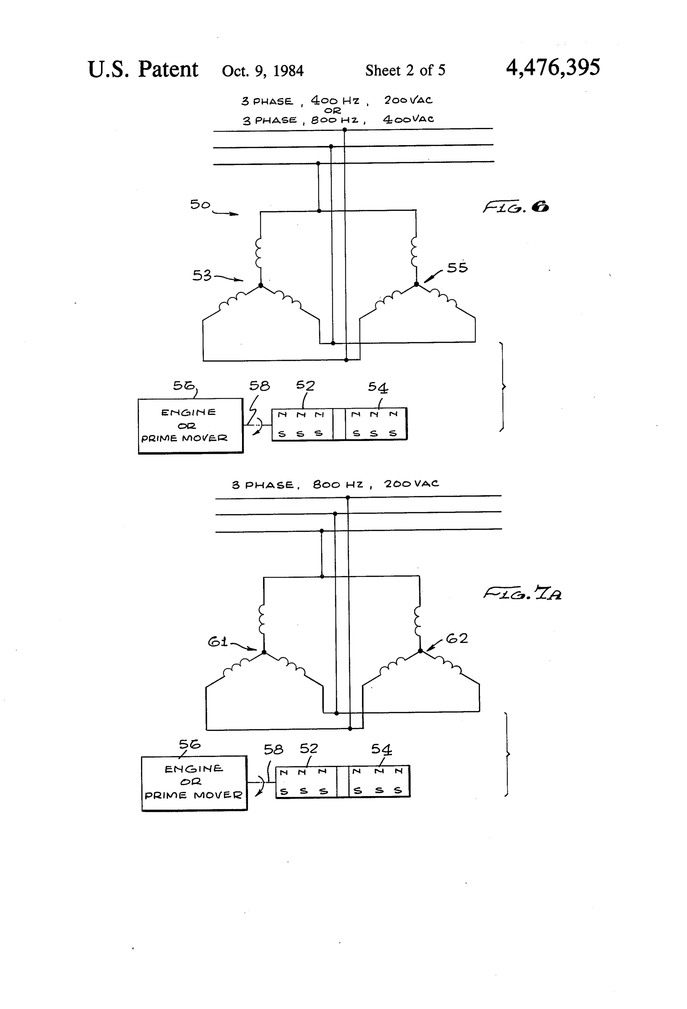
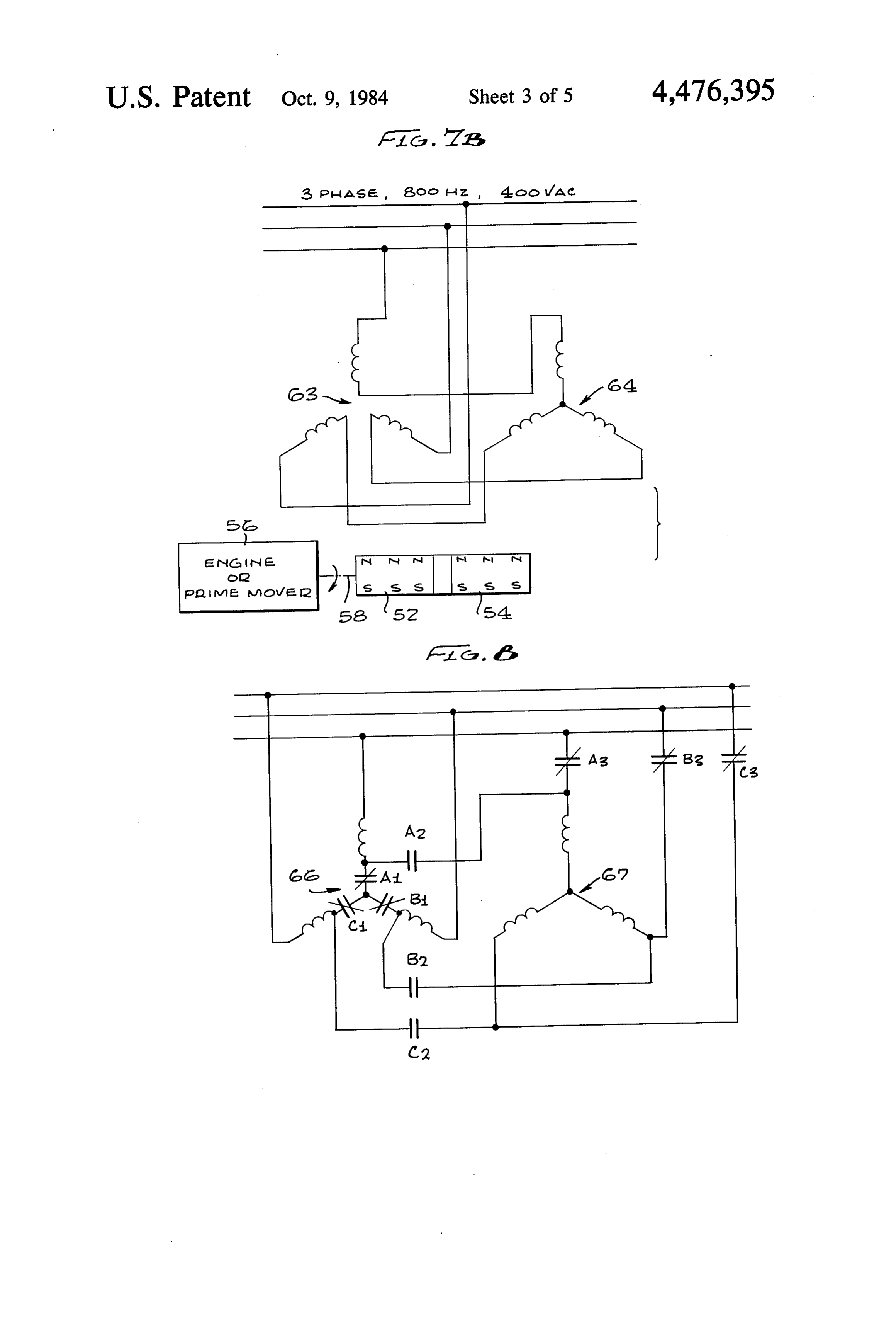
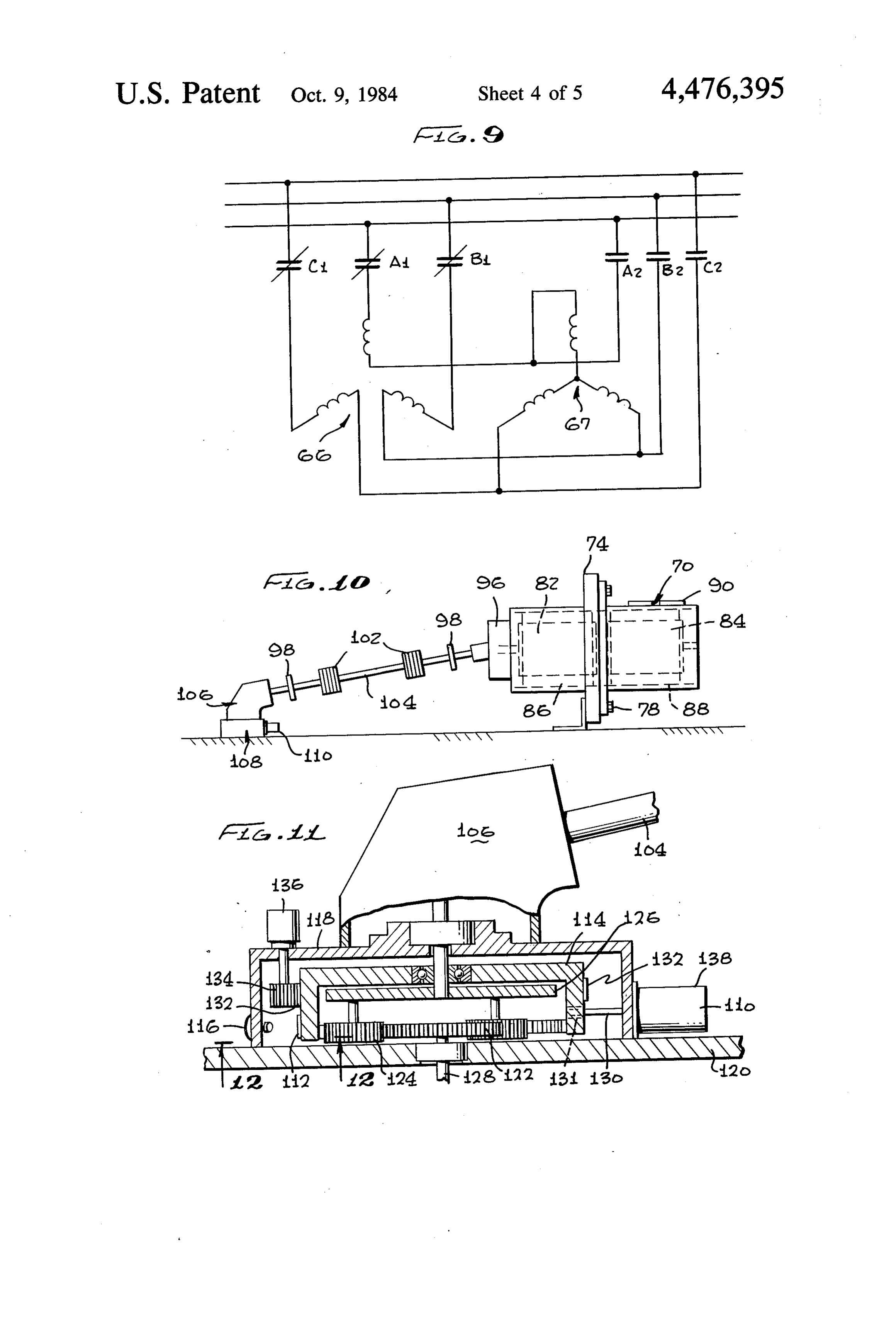
quirements discussed hereinabove are simplified, but The features and advantages of the FIGS. 7A and 7B such a design results in an elongated generator, which in winding changes are, however, as follows: turn results in a large overhang Xovement, when it is (a) The tandem-generator output voltage can be re attached to the mounting-flange (32). The "side-by 15 duced 50%, to reduce the inrush currents to large side' tandem-generator arrangement (10), on the other induction-motors during starting. hand, provides a lower overhung moment, but the syn (b) The generator output voltage could be reduced chrophasing requirements are somewhat more difficult 50% to reduce loads, in an emergency, when there and protracted. might be a lack of cooling capability. Induction The significant feature that only a single shaft drive is 20 motors, however, would have to be isolated used for both tandem generators (10), (10) (in the hous (turned off) in this mode; otherwise, they would be ing), appears to abrogate the dual-redundancy capabil subject to excessive rotor heating. ity of the machine. However, it is to be realized that the FIG. 8 shows the alternative wiring arrangement reliability of an electric power channel is dependent not wherein three-phase contactors (A1, B1, C1), (A2, B2, only upon the generator, but upon many other system 25 C2), and (A3, B3, C3) provide the ability to connect the component elements; e.g., voltage regulators, supervi windings (66), (67) either parallel, as in FIG. 6, or in sory control panels, differential current transformers, series, as in FIG. 7. When the three-phase contactors wiring, power-contactors, etc.; a failure of any one of (A2, B2, C2) are open, and the contactors (A1, B1, C1) these elements, or an electrical failure in the generator and (A3, B3, C3) are closed, the windings (66), (67) are itself, would cause loss of that power channel. The 30 in parallel; when the contactors (A1, B1, C1) and (A3, probability of a shaft failure is therefore considered B3, C3) are open and the contactor (A2, B2, C2) is statistically remote, compared to the other multiple closed, the windings (66), (67) are in series. failure modes possible in the power-channel. A primary feature of the FIG. 8 arrangement is that FIG. 6 schematically represents an "in-line' tandem the tandem-generator can be used as a full capacity generator configuration (50) which is designed and 35 machine in either configuration, i.e., if each winding is wired as, for example, a three-phase 800 Hz 400 VAC rated for 100 KVA, the machine can provide an output machine. The generator includes in-line rotors (52), (54) 200 KVA in both configurations. In one configuration shown driven by an aircraft engine (56) via a drive shaft at 200 volts 577 amps and, in the other case, 400 volts at (58), and stator windings (53), (55) shown connected in 289 amps.
parallel. The tandem generator (50) can also be used as In the FIG. 9 arrangement of the tandem-generator a three-phase 400 Hz 200 VAC machine without any of the present invention, each phase is center tapped. design change by running it at fifty percent of the 800 Thus, depending on the various positions of three-phase Hz synchronous speed: at this lower speed, the output contactors (A1, B1, C1), (A2, B2, C2), the whole wind of the machine will also be reduced 50%. ing or half a winding may be used for each phase. It When the tandem generator (50) is used as a starter 45 might be desirable, for example in starting a motor, generator, the 200 VAC 400 Hz power would corre temporarily to reduce voltage. Normally, contactor spond to the typical 50% ground idle speed of the en (A1, B1, C1) is closed and contactor (A2, B2, C2) is gine (56). In the "start mode', when the permanent open, allowing the machine to operate at 400 V. When, magnet-generator (50) is used as a synchronous-motor however, contactor (A1, B1, C1) is open and contactor starter, the voltage and frequency would be pro 50 (A2, B2, C2) is closed, only the right hand section of the grammed from a very low value, up to the 200V/400 machine is used and so the output voltage and KVA are Hz level, at a rate to control the acceleration-rate of the reduced 50%. Of course it might be desired to use com engine (56). This operation is as described in co-pending binations of the various systems described in FIGS. 6-9.
1980 for "Direct Driven Generator System for ECS 55 dem-generator (70) in accordance with the present in and Engine Starting", and 220,371, filed Dec. 29, 1980 vention wherein a central mount (72) is utilized to over for "Induction-Generator/Dual Samarium-Cobalt Gen come overhung moment problems associated with "in erator Combination', both assigned to the assignee line' configurations, In this case, the tandem-generator herein. (70) is secured via a centrally located flange (72) to a FIGS. 7A and 7B show an alternative utilization of 60 structural mount pad (74) relative to an aircraft engine the tandem-generator of the present invention wherein (76) by a plurality of bolts (78) (two shown). The tan the stated phase windings (61), (62), (63), (64) are con dem-generator (70) is shown with its two permanent nected in parallel (FIG. 7A), or in series (FIG. 7B). In magnet sections (82), (84), dual AC armatures (stators) both cases the machine operates as an 800 Hz generator, (86), (88), and AC terminal blocks (92). but its voltage can be changed in a 2:1 ratio, to enable it 65 One end of the tandem-generator housing (94) is pro to operate as a 200VAC 800 Hz machine, or a 400 VAC vided with a bevel gearbox arrangement (96). The bevel 800 Hz machineAThe constraints on the use of this gear drive is connected via two fixed plate couplings machine are as follows: (98) and two in line flex couplings (102) positioned
Page 10
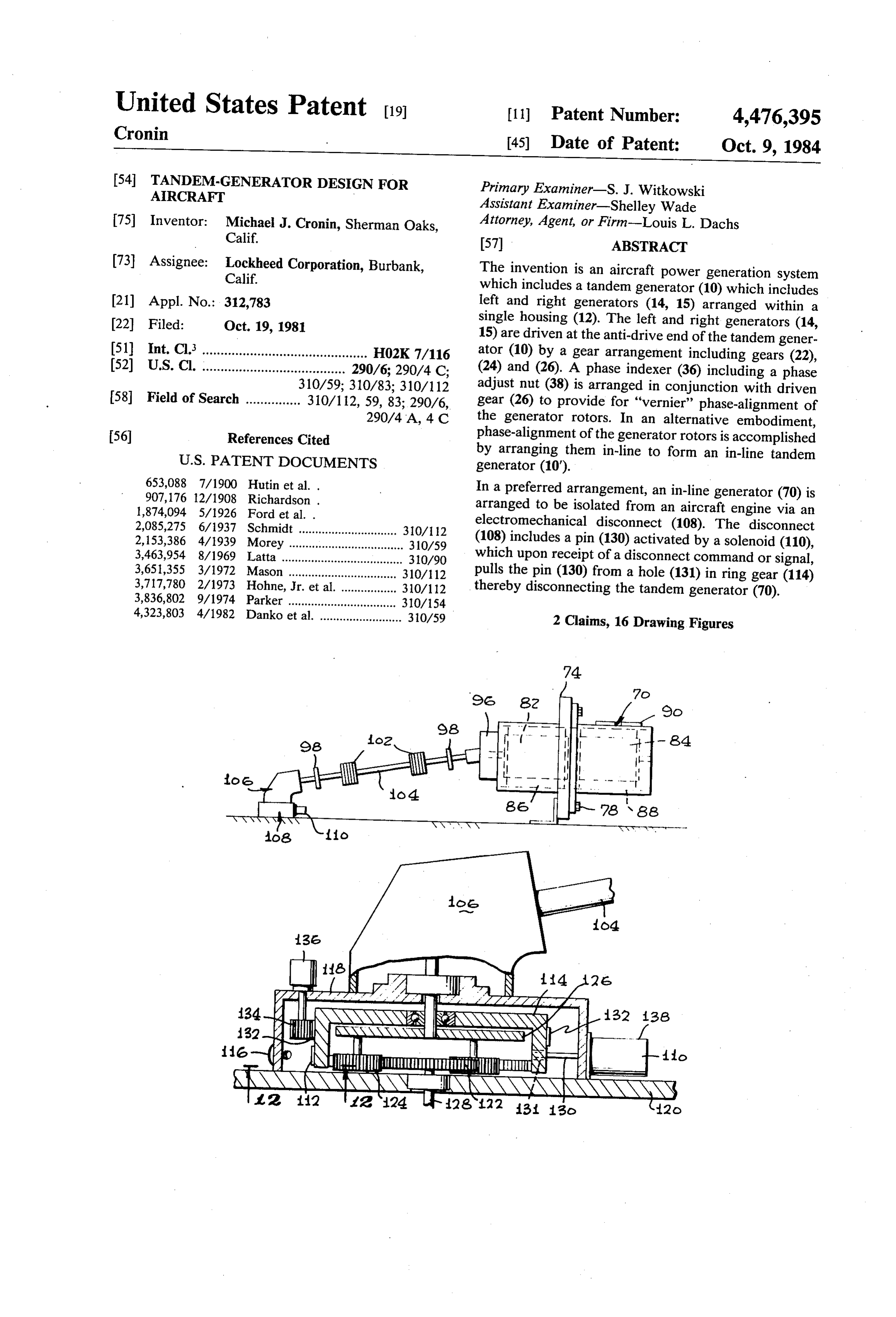
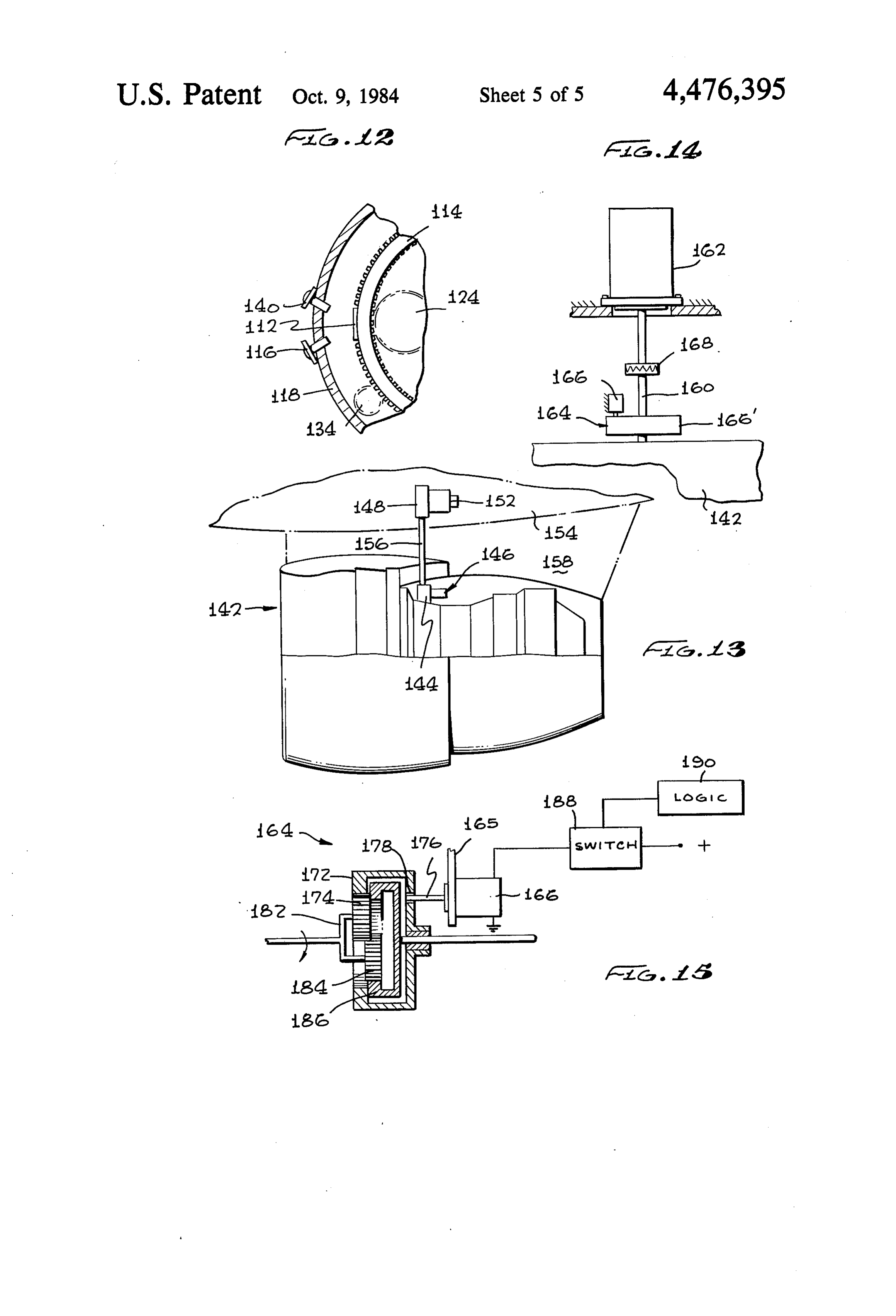
along power transmission shaft (104) to an angle gear photo transistor (140). A change of state of the box (106) driven by the engine (76). This allows the photo transistor (140) actuates a light (not shown) power transmission shaft (104) and the flex couplings to indicate line-up of the pin (130) with the hole (102) to be slid between (or removed from) the fixed (131). At this point, the pin (130)-under pressure plate couplings (98). of a spring-is forced into the hole (131) when the The permanent magnet machines, such as the perma electrical latch on the solenoid is interrupted; and nent magnet tandem AC generator (70), cannot be de (2) A check is made to see that the solenoid pin (130) energized unless the drive source is itself isolated. has re-engaged with the hole (131). This engage Therefore in the event of a fault in the armature wind ment will also be indicated by a high increase in the ings of the machine, the present invention provides an 10 torque at the socket (136). automatic disconnect method to prevent the possibility FIGS. 13-15. show another embodiment of a fast of destructive fault currents. acting mechanical shaft-disconnect control in accor Referring to FIG. 10, an electromechanical discon dance with the present invention that can isolate an nect (108) including an electric solenoid (110) is shown engine (142) from a remote-driven accessory, thereby interposed as an integral part of the transmission mecha 15 protecting it against mechanical-seizures and other nism for driving the tandem AC generator (70). Since it problems such as loss of cooling, etc., that might occur is relatively simple to detect overcurrents, the electro at remote locations. FIG. 13 shows a typical aircraft mechanical disconnect (108) arrangement of FIG. 10 arrangement where a vertical power-take-off drives a will ensure rapid isolation of the generator (70) right at generator and/or a gearbox located in a pylon, wing or the engine take-off in the event of such faults. The dis 20 fuselage location. In the FIG. 13 schematic, the engine connect (108) can also be designed to operate in the (142) drives, through an electromechanical disconnect event of any failure in the power transmission system (144) to a remote gearbox (148), which in turn drives itself. the generator (152) or other accessories. Control of the The electromechanical disconnect (108) of FIG. 10 is disconnect (144) is effected via the solenoid (186). As shown in greater detail in FIGS. 11 and 12. FIG. 11 25 the remote gearbox (148) is driven by the drive shaft shows the electromechanical disconnect (108) to in (156) (which passes through the pylon (158)), the engine clude an optical position sensor comprising a reflector (142) can be protected against shaft bearing failures, (112) on a ring-gear (114) and a light emitting diode gearbox/generator failures, etc., by operation of the (116) in the gearbox housing (118). The housing (118) is electromechanical disconnect (144) which is located in shown attached to the top (120) of the engine case and 30 position as shown in FIG. 13.
encloses a planetary differential including a sun gear Referring now to FIGS. 14 and 15, the electrome (122), planet gears (124), the ring gear (114), and a pla chanical disconnect and speed changer assembly (164) net-carrier (126). An interfacing takes place therefore described therein fulfills the dual role of a disconnect from the engine to the gearbox (106) via the power and a speed-change element in the drive shaft system. input shaft (128) and the electromechanical disconnect 35 Usually, the power take-off shaft (160) will not be at the (108). right speed for the remote gearbox or generator (162). The ring gear (114) of the differential is normally held Therefore, by use of one or more planetary gear sets, a against rotation by a pin (130) inserted in a hole bored in speed-change can be accomplished in the electrome the ring housing which includes outside teeth (132) chanical speed-change and disconnect assembly (164), which mesh with a gear (134) connected through the which is located close to the take-off point of the power housing (118) to a socket (136). When power input shaft shaft on the engine (142). An electric-solenoid (166) is (128) rotates and the ring gear (114) is locked, velocity shown located above the assembly (164), but is fixed to and torque is transmitted via the sun gear (4), through the pylon or other structure (165) independently of the the planet gear (124) and planet carrier (126) to the engine (142). A diaphragm-shaft (168) is shown to take output transmission shaft (104). 45 care of vibrational, and/or differential misalignments, . When an abnormal electric current is detected in the but this is not pertinent to the novel features of the tandem generator, the electric solenoid (110) is ener speed-changer and disconnect assembly (164) of the gized to withdraw the pin (130) from the hole (131) in present invention.
the ring gear housing. At this point, the ring gear (114) FIG. 15 is an enlarged schematic representation of spins freely and is unable to react any torque: transmis 50 the electromechanical disconnect and speed changer sion of power to the output shaft (104) is not therefore assembly (164); again, the gear set arrangement and possible. The tandem-generator is thus isolated from its planetary configuration are typical only. The feature of drive source, thereby preventing any electrical, thermal the planetary gear system, however, is that the ring gear or mechanical damage. (172), interfacing with the left carrier gear (174), is Indication that the solenoid is in its "disconnect' 55 constrained against rotational motion by the pin (176) of position can be noted by the protrusion of the pin (130) the solenoid (166), protruding through a hole (178) in through the end of the solenoid enclosure (138). Since the housing of ring-gear (172). Thus, with the ring gear the electric solenoid (110) is now electrically "latched (172) so constrained, it is able to react the torgue of the out", "reset' can only be accomplished by a deliberate input-carrier (182), and thus transmit the torque to the mechhanical action on the ground. right-gear (184) which, in turn, transmits it to the output When the fault has been eliminated, reset is accom ring-gear (186). The input-drive-to-output-drive tor plished as follows: w que/speed transmission is therefore simply accom (1) A socket wrench (not shown) may be attached to plished. Disconnect is accomplished by activation of the socket (136) and turned, (or the socket may be the solenoid (166) via a switch (188) which is controlled turned by hand), until visual light indication is 65 by the logic system (190). Various gear-ratios in the observed via the light detection system shown in disconnect and speed changer assembly (164) could, of FIG. 12. Light from the LED (116) strikes the course, be provided by utilizing suitable "stepped reflector (112) and is reflected for detection by a gears'.
Page 11
Under normal conditions, torque/speed transmission INDUSTRIAL APPLICATION operation is accomplished with the ring-gear (172) con strained. If, however, the "logic' (190) detects an over The tandem generator and electromechanical discon temperature condition, an excessive-torque, or exces 5 nect of the present invention is useful for installation in sive current, or, a "differential-current' fault in the aircraft by mounting to one or more aircraft engine generator (162), a "turn-on' command is given by the to drives to provide reliable and needed electrical power logic (190) to gate an SCR via a normally closed switch, various aircraft subsystems. I claim:
both located in switch assembly (188). At this time the 1. An aircraft power generation system comprising in SCR turns on and energizes solenoid (166), causing the 10 combination:
solenoid-pin to be withdrawn from the hole (178) in the an aircraft engine, said engine having at least one ring gear-housing. The left carrier gear (174) is now drive shaft;
able to spin free and it is therefore no longer able to a tandem generator driven by said at least one drive react the torque of the gear train. Electrically, the shaft, said tandem generator comprising two per switch assembly (188) will insure that the solenoid (166) 15 manent magnet AC synchronous generators ar is "latched-up' until it can be de-energized at a later ranged in a single housing; time by opening the normally closed switch. Therefore, a mechanical drive mechanism interactively inter once the disconnect has operated in flight, it cannot be posed between said at least one drive shaft and said tandem generator; and reset again until the aircraft is on the ground and the 20 disconnect means associated with said mechanical engines have been shut-down. drive mechanism for selectively isolating said en From the foregoing it can be seen that a tandem-gen gine from said tandem generator when said engine erator and power generation system has been provided is running, said disconnect means comprising: in accordance with the present invention which utilizes means for speed adjustment between said engine a single cooling loop, a single mount capability, an ad 25 and said tandem generator, said speed adjust justable gear-ratio capability, single mechanical shaft ment means comprising a planetary differential input, and a phase alignment capability. As stated, the having interactive sun gear, planet gear, planet in-line generator is more capable of easy production carrier and ring gear elements within a planetary phase-alignment, but there may be instances where the 30 differential housing for carrying out said speed adjustment;
overall length, or the L/D ratio, may be too large. disconnect means including an electric solenoid Nevertheless, it is still in many instances a practical and mounted to said housing and adapted to actuate viable configuration. In either configuration discussed pin means for selectively locking or releasing hereinabove, an efficient and fast acting disconnect said ring gear element by moving said pin into and/or disconnect/transmission means is provided to 35 "lock" and “release' positions; give the required drive characteristics, while simulta electromechanical switch means for actuating said neously providing protection against overload, over electric solenoid and further including logic heat, bearing breakdown, and the like conditions in the means for activating said switch means respon power generation system. sive to abnormal torque of said mechanical drive It is apparent that there has been provided with this system, mechanical overheating of said power invention a novel Tandem-Generator Design for Air generation system and electrothermal overheat ing of said power generation system; and craft which fully satisfies the objects, means, and advan means for monitoring the position of said ring gear. tages set forth hereinbefore. While the invention has 2. An aircraft power generation system as in claim 1 been described in combination with specific embodi 45 wherein said monitoring means comprises an electro ments thereof, it is evident that many alternatives, modi optical system comprising light emitting means fications and variations will be apparent to those skilled mounted to said housing, reflector means mounted on in the art in light of the foregoing description. Accord said ring gear, and photo transistor means mounted on ingly, it is intended to embrace all such alternatives, 50 said housing, said light emitting, reflector and photo modifications and variations as fall within the spirit and transistor means being arranged relative to each other broad scope of the appended claims. such that reflected light from said reflector activates The disclosures of the aforementioned United States said electric solenoid when said gear housing is in a patents and patent applications are incorporated by whereby predetermined position relative to said ring gear reference herein.
said pin engages ak hole insk said ring gear.
Provenance
- Collection
- Cited prior art
- Original PDF
- patentimages.storage.googleapis.com →
- Filed
- 1981-10-19
- Pages
- 11
- Method
- pdftotext (the PDF's own text layer) + pdftoppm 300dpi page scans
- Source
- Google Patents bibliographic record
- Granted
- 1984-10-09
- Inventors
- Michael J. Cronin; Lockheed Corp
- Transcribed from
- patentimages.storage.googleapis.com →