patent · US4291235
Windmill
22 September 1981
Page 1 — bibliographic record
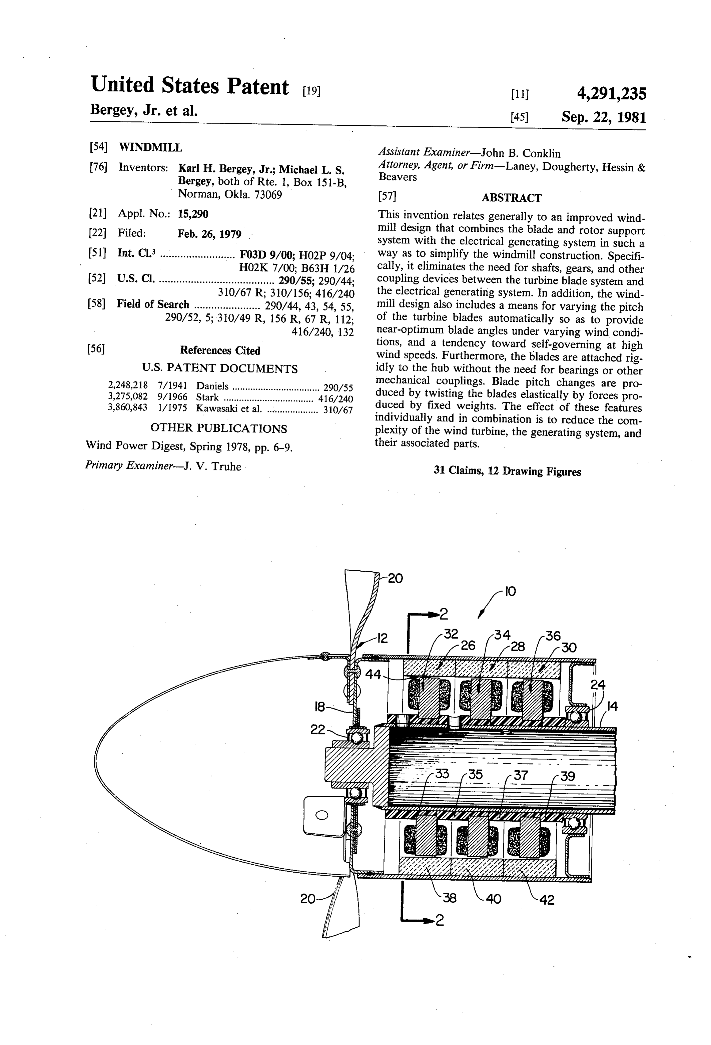
United States Patent (19) 11 4,291,235 Bergey, Jr. et al. 45) Sep. 22, 1981 (54) WINDMILL Assistant Examiner-John B. Conklin 76 Inventors: Karl H. Bergey, Jr.; Michael L. S. Attorney, Agent, or Firm-Laney, Dougherty, Hessin & Beavers
Bergey, both of Rte. 1, Box 151-B,
Norman, Okla. 73069 57) ABSTRACT 21 Appl. No.: 15,290 This invention relates generally to an improved wind 22 Filed: Feb. 26, 1979 mill design that combines the blade and rotor support system with the electrical generating system in such a 51) Int, Cl. .......................... F03D 9/00; H02P 9/04; way as to simplify the windmill construction. Specifi HO2K7/00, B63H 1/26 cally, it eliminates the need for shafts, gears, and other 52 U.S.C. ........................................ 290/55; 290/44; coupling devices between the turbine blade system and 310/67 R; 310/156; 416/240 the electrical generating system. In addition, the wind 58) Field of Search ....................... 290/44, 43, 54, 55, mill design also includes a means for varying the pitch 290/52, 5; 310/49 R, 156 R, 67 R, 112; of the turbine blades automatically so as to provide 416/240, 132 near-optimum blade angles under varying wind condi 56) References Cited tions, and a tendency toward self-governing at high wind speeds. Furthermore, the blades are attached rig
2,248,218 7/1941 Daniels .................................. 290/55 mechanical couplings. Blade pitch changes are pro 3,275,082 9/1966 Stark .................... ... 416/240 duced by twisting the blades elastically by forces pro 3,860,843 1/1975 Kawasaki et al..................... 310/67 duced by fixed weights. The effect of these features individually and in combination is to reduce the com
OTHER PUBLICATIONS plexity of the wind turbine, the generating system, and Wind Power Digest, Spring 1978, pp. 6-9. their associated parts.
Primary Examiner-J. V. Truhe 31 Claims, 12 Drawing Figures
Page 2
Drawing sheet — no readable text.
Page 3
Drawing sheet — no readable text.
Page 4
Drawing sheet — no readable text.
Page 5
Drawing sheet — no readable text.
Page 6
Drawing sheet — no readable text.
Page 7
Drawing sheet — no readable text.
Page 8
of the centrifugal force acting on this out-of-plane bal
WINDMILL ance weight acts to twist the blades about their respec
BACKGROUND OF THE INVENTION
tive radial axes so as to decrease the pitch of the blades with increasing rotational speeds. The system is con 1. Field of the Invention structed so that a radially outer portion of the blades The present invention relates to a device with electri will stall at a predetermined rotational velocity thereby cal, mechanical and aerodynamic features that enable it causing the system to be self-governing at that velocity. to convert the energy in the wind to usable electrical Out-of-plane balance weights have previously been power. used with torsionally non-flexible blades having a short 10 torsionally flexible connecting means located between a 2. Description of the Prior Art
As the supply of conventional fossil fuels decreases radially inner end of the blade and the hub. In those and their costs increase, modern industrial society will apparatus the out-of-plane weight has typically been turn increasingly to alternate sources of energy. Of connected adjacent the connection of the radially inner these, windpower is one of the most promising since it end of the blade and the torsionally flexible connecting is abundant, widely distributed and environmentally 5 means. In such apparatus, the change in blade pitch benign. It has also established its ability to meet the which occurs with varying rotational speed is a uniform needs of society through usage over many hundreds of change along the entire radial length of the blade, as years and in many parts of the world. In today's indus opposed to the continuously varying change in blade trial society, however, windpower will be accepted as a pitch which occurs with the present invention. An ex satisfactory replacement for conventional fuels only if it 20 ample of such a prior art device is disclosed in Cheney is convenient to use and low in cost. Both of these con and Spierings, "Self-regulating Composite Bearingless ditions are satisfied if the wind machine is simple in Wind Turbine", report No. C00/2614-7612 (September construction, aerodynamically efficient and capable of 1976) prepared for the United States Energy Research unattended operation.
Since the desired blade angle or pitch of horizontal 25 and Development Administration under Contract No. E(11-1)-2614. Another apparatus similar to that of axis wind turbines varies with wind speed and rotational Cheney and Spierings is disclosed in Wind Power Digest, speed, it has been common practice to support the tur No. 12, pp. 7-9 (Spring/Summer 1978), although suffi bine blades in bearings that allow the blades to rotate cient facts are not presently known about their longitudinal axis. In this way, the blade whether this latter disclosure, or the to us to determine apparatus referred angles may be changed through suitable mechanical 30 linkages and control systems that sense the need for a to therein, constitutes prior art with respect to our in change in blade angle and provide the necessary input vention.
signals. Thus, in the past, windmills for electrical gener The elimination of gearing between the turbine blade ation have gained efficiency at the cost of aerodynamic, assembly and the electrical generating system is mechanical and control system complexity. 35 achieved in the windmill of the present invention by the Conversely, simple windpower machines with rigid use of an alternator comprising a stationary multiple fixed-pitch blades operate at their highest efficiency pole wound stator, and a multiple permanent magnet only at a single combination of wind speed and rota structure rotatably mounted coaxial with the stator. tional speed. At all other combinations, the blade angle The permanent magnet structure is rigidly attached to is either too high or too low. As a result, fixed-pitch 40 the rotating turbine blade system so as to rotate there turbines operate at relatively low efficiency, require with, thereby eliminating the need for drive gears or the high start-up windspeeds, and have little inherent ten like between the turbine blade system and the electrical dency toward self-governing at high wind speeds. generating system. Similar alternators, used singly, that Thus, the alternatives have been, on the one hand, is without coaxially stacking a plurality of alternators, relatively efficient machines that are complex, expen 45 are known to the art as described in T. Carmichael, sive, and difficult to maintain, and, on the other hand, "Ignition and Battery Charging with Permanent Mag relatively inefficient machines that are simple, inexpen net Alternators', SAE paper no. 670046 presented at sive and difficult to control at high wind speeds. Automotive Engineering Congress, Jan. 9-13, 1967, in Furthermore, the disparity between the relatively Detroit, Mich.
slow rotational speed for wind turbines and the high 50 SUMMARY OF THE PRESENT INVENTION rotational speed for most electrical generators has led to the use of gears, belts or other speed-increasing devices It is the object of the present invention to provide a between the turbine and the generator. The resulting means by which wind energy may be converted to complexity has tended to increase the initial costs and electrical power at minimum cost through a combina the maintenance requirements for windpower genera 55 tion of simplified mechanical and aerodynamic features tors of this type. of the complete wind turbine generating system. The present invention overcomes these problems to a The improved windmill construction eliminates all large extent by providing a variable pitch turbine blade gearing between the turbine blade assembly and the assembly having no moving parts, and by eliminating all electrical generating system. This simplification is ac gearing between the turbine blade assembly and the 60 complished by incorporating the electrical generation electrical generating system. system into the rotor support system and by using per The turbine blade assembly will start-up at low wind manent magnet alternator components that are compati speeds, and is self-governing at high wind speeds. This ble with this type of construction. Specifically, the elec is accomplished by the use of a plurality of torsionally trical generating system consists of a number of concen flexible cambered sheet airfoil blades rigidly mounted at 65 trically stacked (modular) stationary multiple-pole their radially inner ends to a central hub. These blades wound stators fixed to a non-rotating shaft mounted have an out-of-plane balance weight attached near the with its axis paralled to the wind flow. An equal number radially outer end of their leading edge. A component of complementary stacked multiple permanent-magnet
Page 9
field elements are rotatably mounted co-axially with the from the generator without the need for slip-rings or stators. Poles of adjacent stators are staggered so as to other devices for transferring current through rotating minimize the cogging effect present in alternators with mechanical components.
permanent magnet field elements. It is therefore an object of the present invention to The turbine blade system comprises a plurality of 5 provide an improved windmill design which eliminates torsionally flexible cambered sheet airfoil blades rigidly the need for any mechanical coupling, by gears or the mounted to the same rotatable structure that supports like, between the turbine blade system and the electrical and contains the permanent-magnet field elements. Al generating system.
though rigidly mounted at their inboard attachment to the hub structure, the blades may be twisted due to their sionAnother object of the present invention is the provi torsional flexibility so as to provide a variable pitch windmill, comprised electrical of an improved
generating system for a plurality of concentrically system. The initial high pitch is set so as to provide a stacked, radially staggered, stationary multiple pole favorable rotational force at low wind speeds to over Stator type alternators.
come the residual magnetic cogging effect. As the rota And another object of the present invention is the tional speed of the turbine increases, the pitch of the 15 provision of a self-governing turbine blade system. blades is automatically and continuously decreased so as to improve the aerodynamic efficiency at high tip speed Yet another object of the present invention is the ratios. This pitch change with increasing rotational provision prising of a self-governing turbine blade system com continuously torsionally flexible cambered sheet speed is obtained through the use of an out-of-plane balance weight attached to the leading edge of the outer 20 airfoils rigidly attached to a central hub, with an out-of portion of each blade. As the rotational speed of the plane weight attached to a radially outer portion of the turbine increases, a component of the centrifugal force leading edge of the blades.
acting on the out-of-plane balance weight applies a Other and further objects and advantages will be torsional force to the outer portion of the torsionally apparent to those skilled in the art upon a reading of the flexible turbine blades, thereby twisting the blades 25 detailed description in conjunction with the accompa about their radial axes in such a way as to decrease the nying drawings.
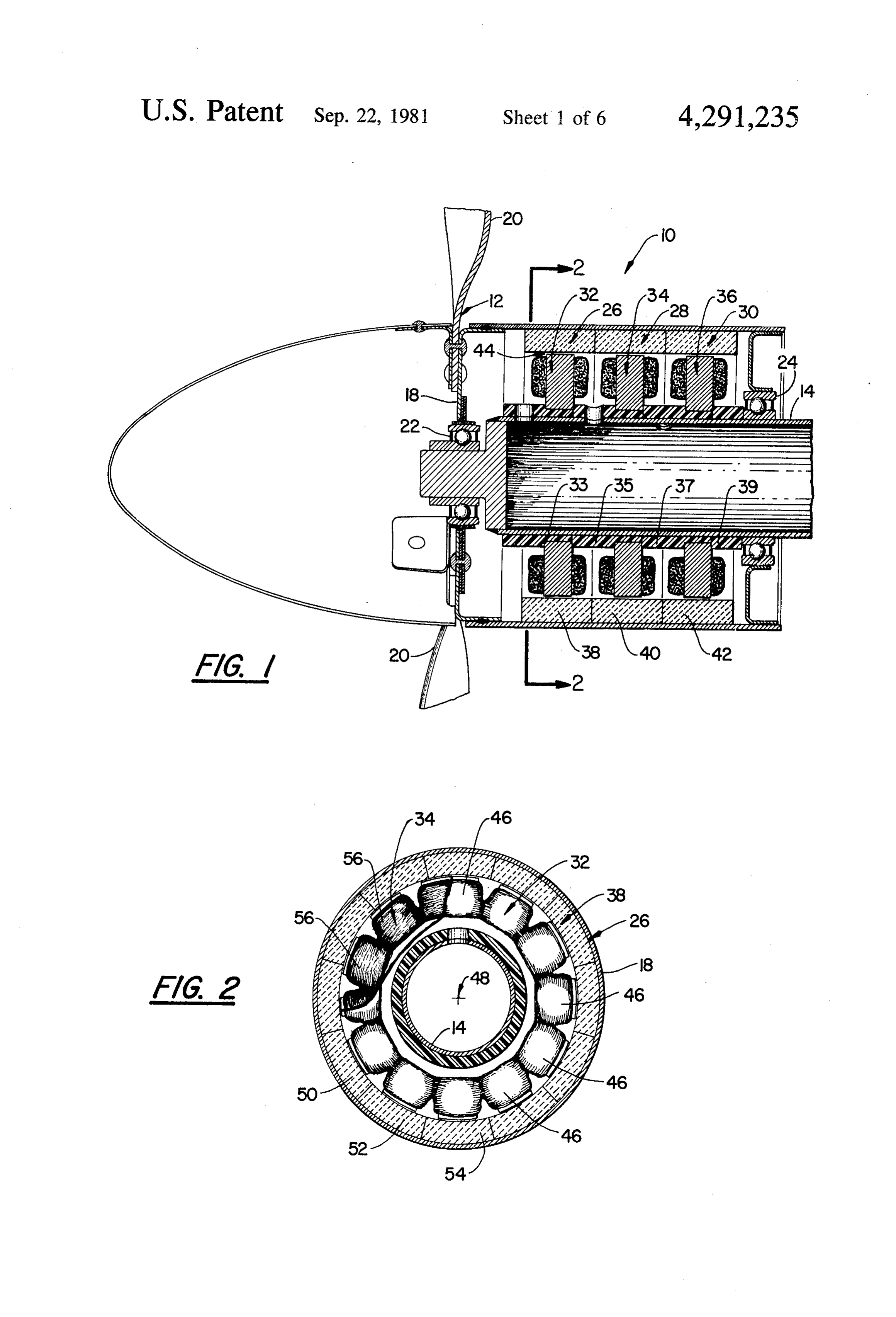
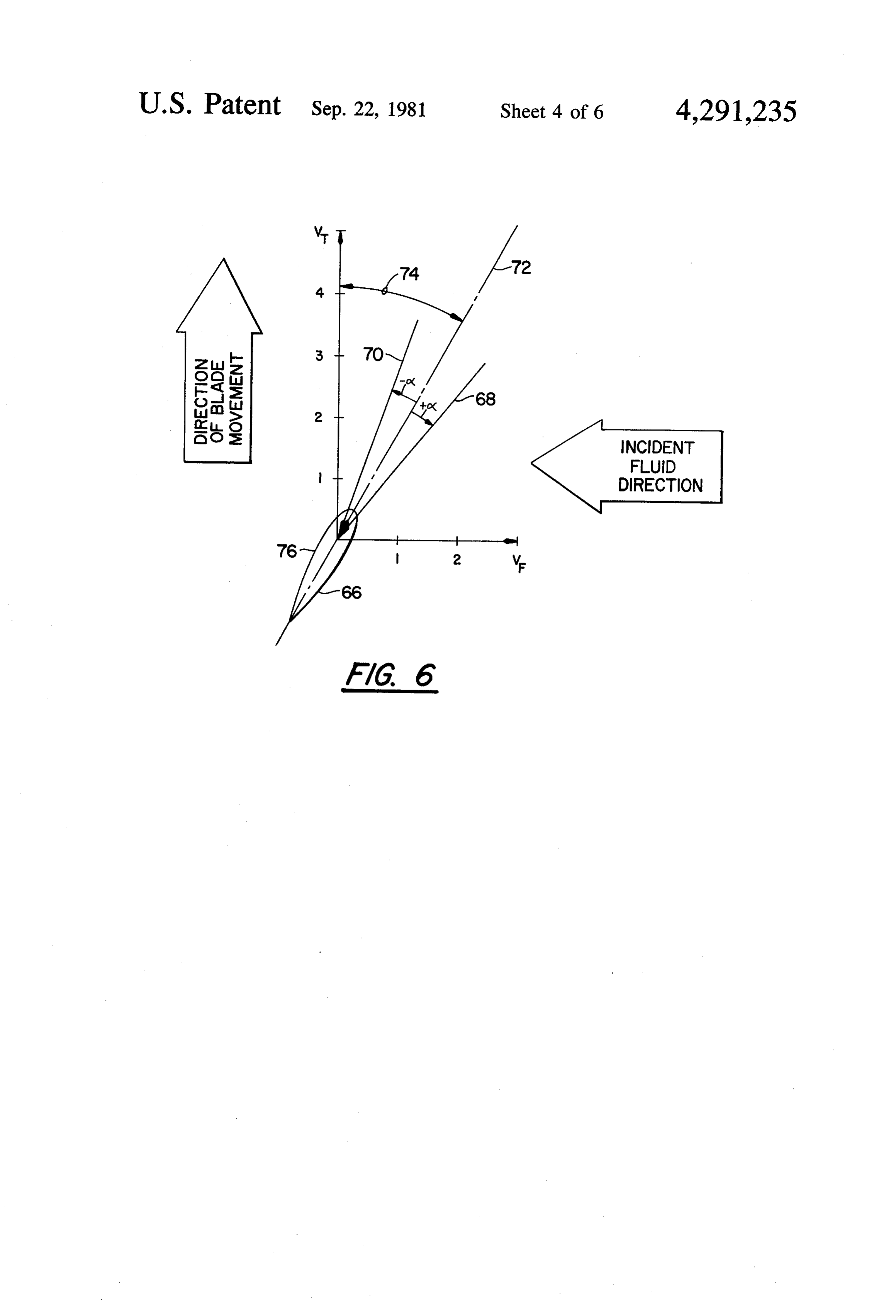
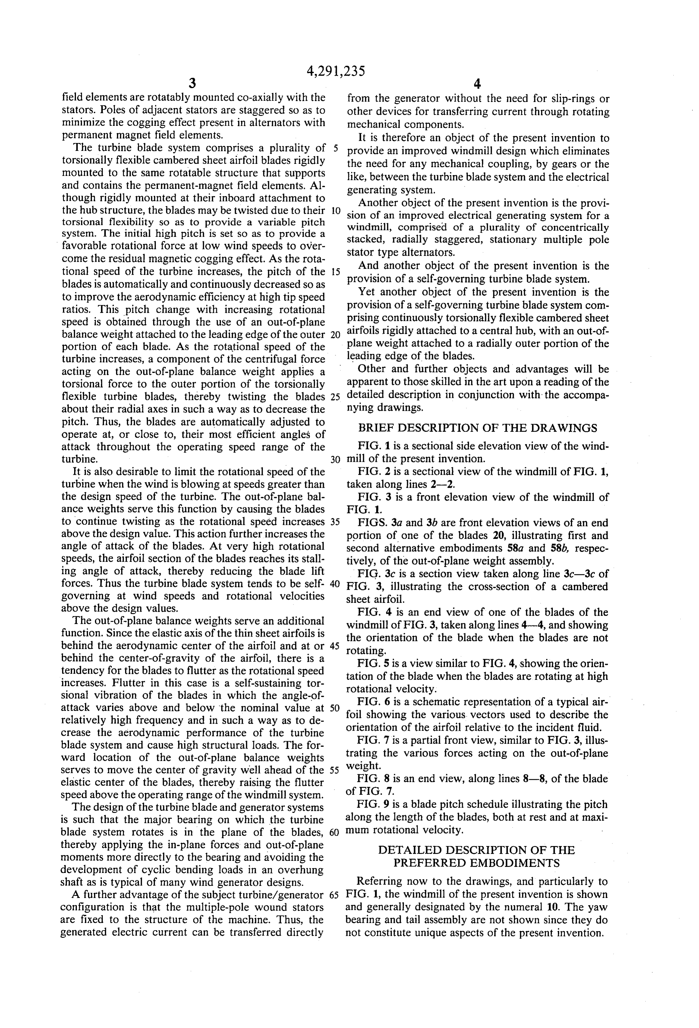
pitch. Thus, the blades are automatically adjusted to BRIEF DESCRIPTION OF THE DRAWINGS operate at, or close to, their most efficient angles of attack throughout the operating speed range of the FIG. 1 is a sectional side elevation view of the wind turbine. 30 mill of the present invention. It is also desirable to limit the rotational speed of the FIG. 2 is a sectional view of the windmill of FIG. 1, turbine when the wind is blowing at speeds greater than taken along lines 2-2.
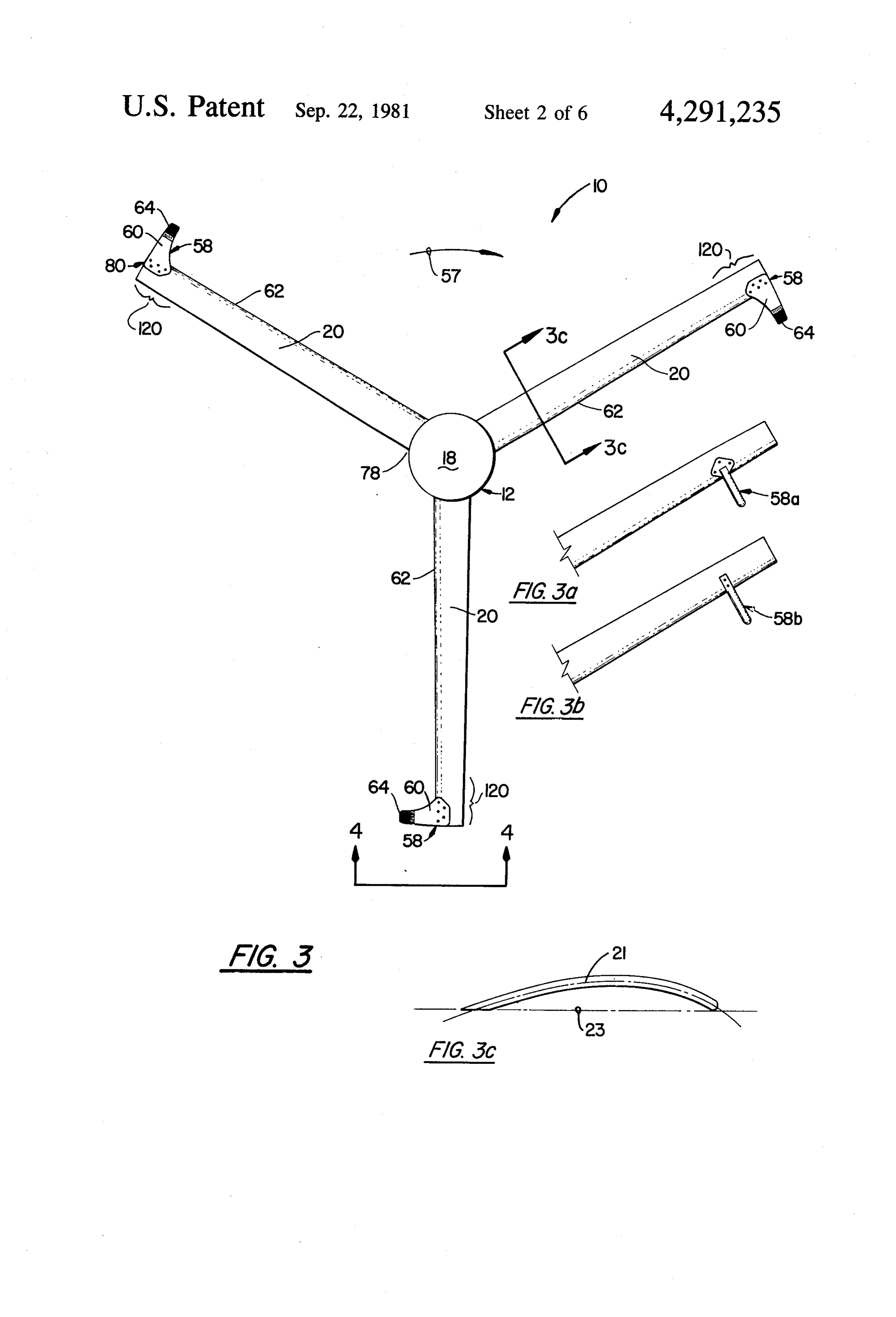
the design speed of the turbine. The out-of-plane bal FIG. 3 is a front elevation view of the windmill of ance weights serve this function by causing the blades FIG. 1.
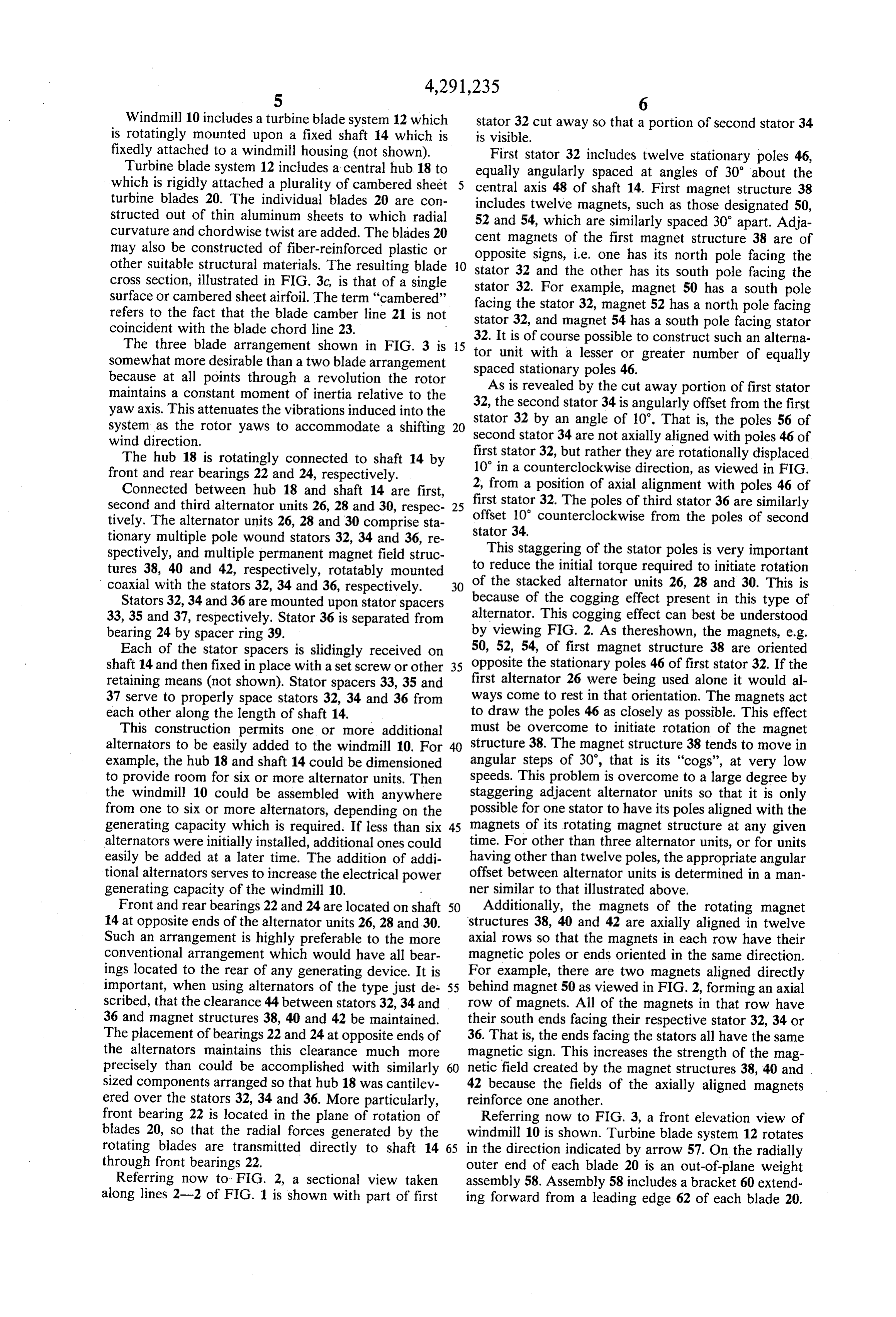
to continue twisting as the rotational speed increases 35 FIGS. 3a and 3b are front elevation views of an end above the design value. This action further increases the portion of one of the blades 20, illustrating first and angle of attack of the blades. At very high rotational second alternative embodiments 58a and 58b, respec speeds, the airfoil section of the blades reaches its stall tively, of the out-of-plane weight assembly. ing angle of attack, thereby reducing the blade lift FIG. 3c is a section view taken along line 3c-3c of forces. Thus the turbine blade system tends to be self 40 FIG. 3, illustrating the cross-section of a cambered governing at wind speeds and rotational velocities sheet airfoil.
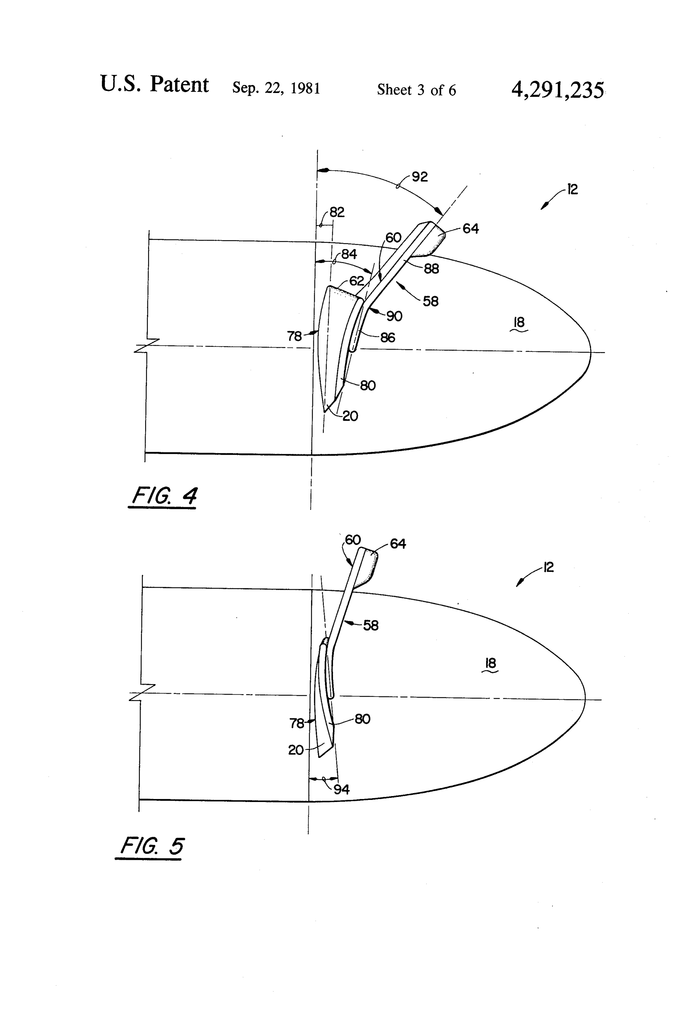
above the design values. FIG. 4 is an end view of one of the blades of the The out-of-plane balance weights serve an additional windmill of FIG. 3, taken along lines 4-4, and showing function. Since the elastic axis of the thin sheet airfoils is the orientation of the blade when the blades are not behind the aerodynamic center of the airfoil and at or 45 rotating.
behind the center-of-gravity of the airfoil, there is a FIG. 5 is a view similar to FIG. 4, showing the orien tendency for the blades to flutter as the rotational speed tation of the blade when the blades are rotating at high increases. Flutter in this case is a self-sustaining tor rotational velocity.
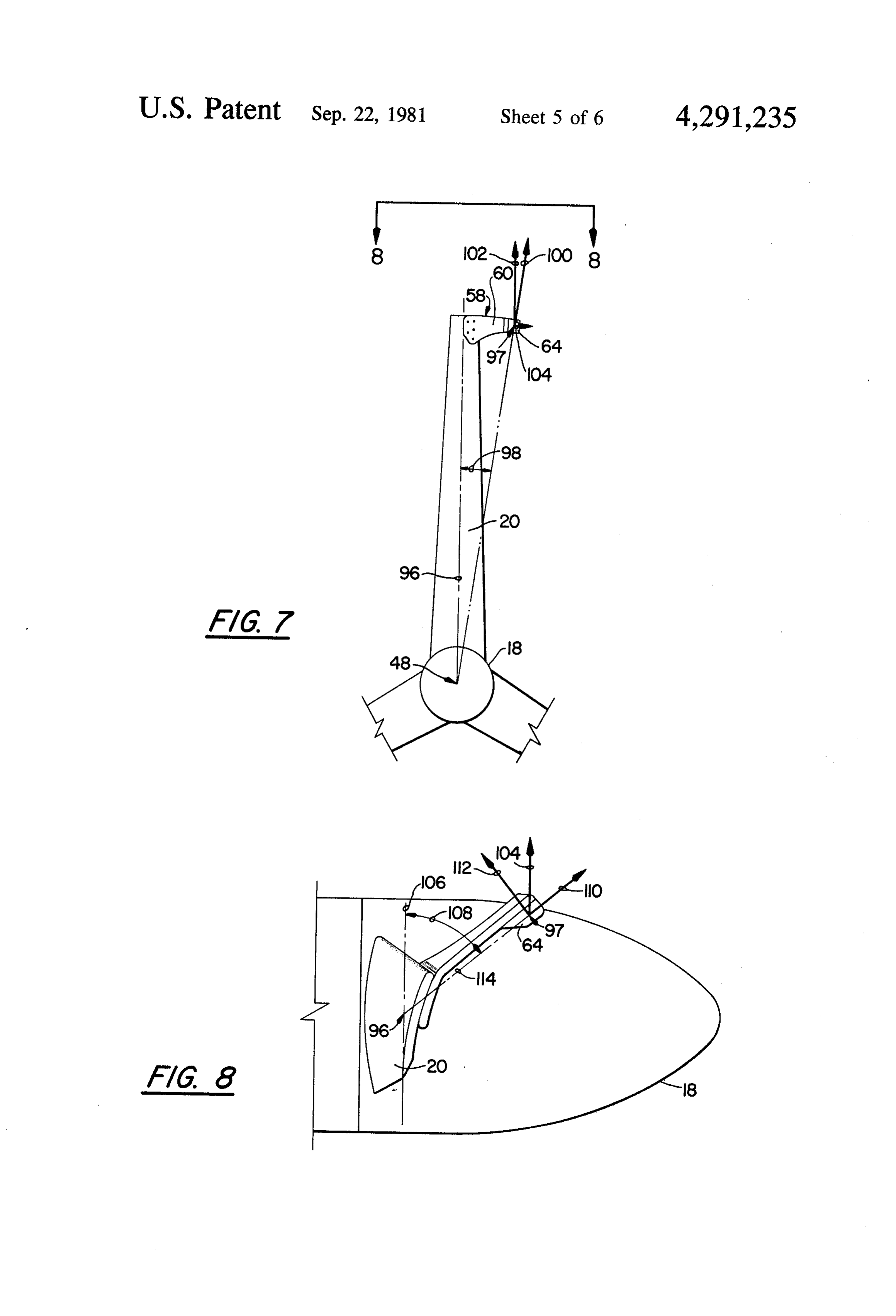
sional vibration of the blades in which the angle-of attack varies above and below the nominal value at 50 FIG. 6 is a schematic representation of a typical air relatively high frequency and in such a way as to de foil showing the various vectors used to describe the crease the aerodynamic performance of the turbine orientation of the airfoil relative to the incident fluid. blade system and cause high structural loads. The for trating FIG. 7 is a partial front view, similar to FIG. 3, illus ward location of the out-of-plane balance weights weight. the various forces acting on the out-of-plane serves to move the center of gravity well ahead of the 55 elastic center of the blades, thereby raising the flutter of FIG. 8 is an end view, along lines 8-8, of the blade
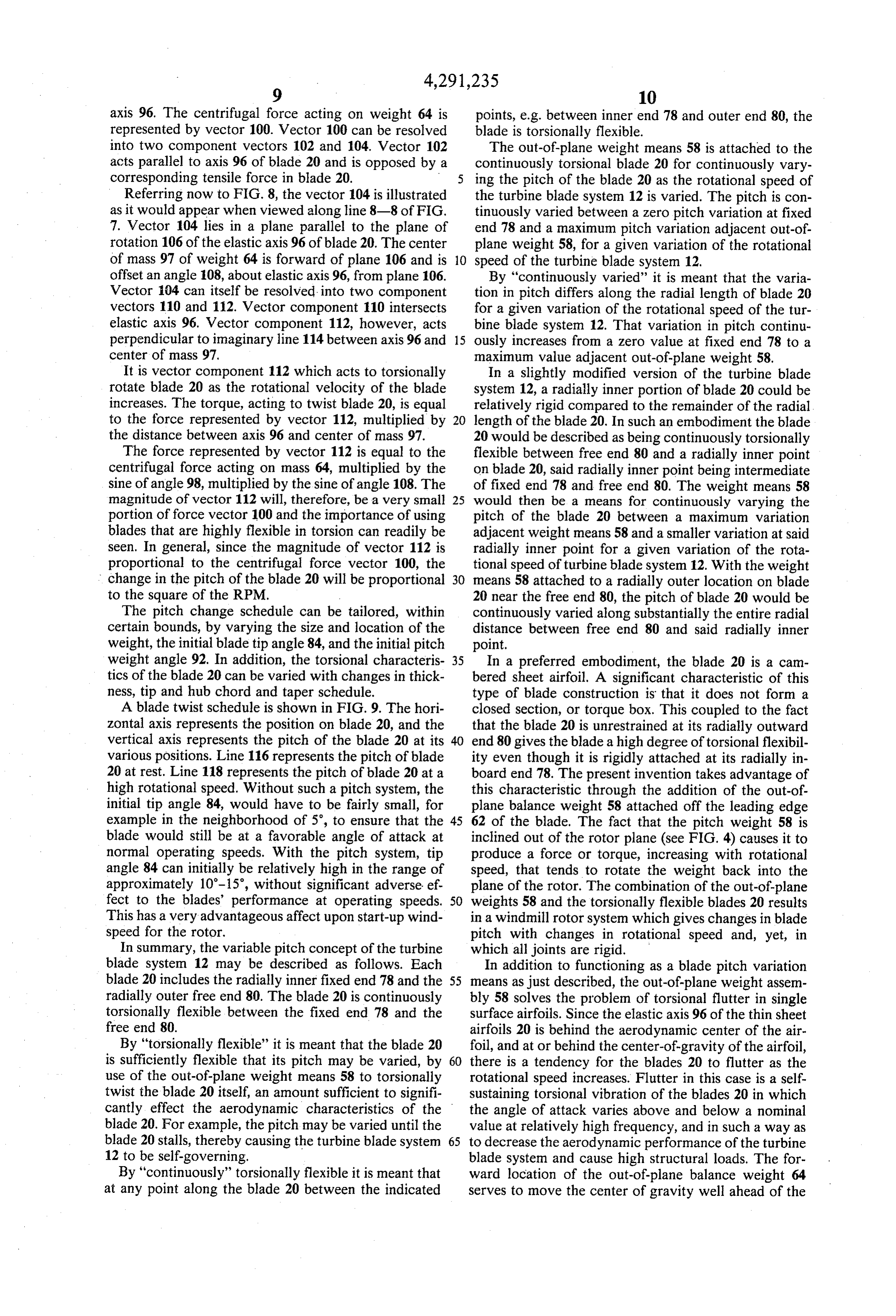
speed above the operating range of the windmill system.
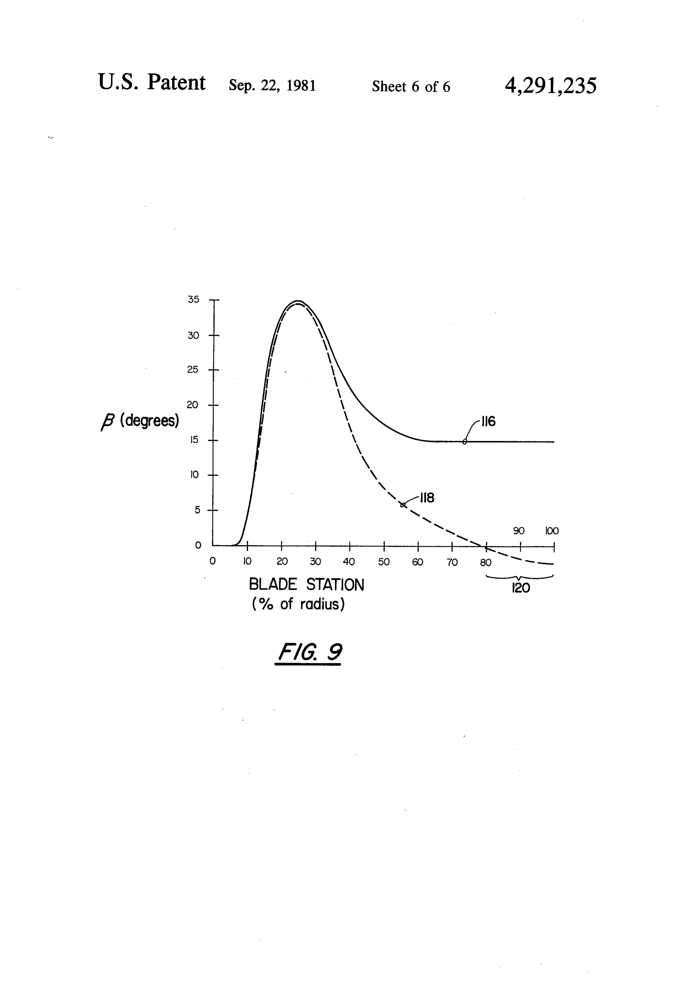
The design of the turbine blade and generator systems FIG. 9 is a blade pitch schedule illustrating the pitch is such that the major bearing on which the turbine along the length of the blades, both at rest and at maxi blade system rotates is in the plane of the blades, 60 mum rotational velocity.
thereby applying the in-plane forces and out-of-plane DETAILED DESCRIPTION OF THE moments more directly to the bearing and avoiding the PREFERRED EMBODIMENTS development of cyclic bending loads in an overhung shaft as is typical of many wind generator designs. Referring now to the drawings, and particularly to A further advantage of the subject turbine/generator 65 FIG. 1, the windmill of the present invention is shown configuration is that the multiple-pole wound stators and generally designated by the numeral 10. The yaw are fixed to the structure of the machine. Thus, the bearing and tail assembly are not shown since they do generated electric current can be transferred directly not constitute unique aspects of the present invention.
Page 10
Windmill 10 includes a turbine blade system 12 which stator 32 cut away so that a portion of second stator 34 is rotatingly mounted upon a fixed shaft 14 which is is visible.
fixedly attached to a windmill housing (not shown). First stator 32 includes twelve stationary poles 46, Turbine blade system 12 includes a central hub. 18 to equally angularly spaced at angles of 30’ about the which is rigidly attached a plurality of cambered sheet central axis 48 of shaft 14. First magnet structure 38 turbine blades 20. The individual blades 20 are con includes twelve magnets, such as those designated 50, structed out of thin aluminum sheets to which radial 52 and 54, which are similarly spaced 30° apart. Adja curvature and chordwise twist are added. The blades 20 cent magnets of the first magnet structure 38 are of may also be constructed of fiber-reinforced plastic or opposite signs, i.e. one has its north pole facing the other suitable structural materials. The resulting blade 10 stator 32 and the other has its south pole facing the cross section, illustrated in FIG. 3c, is that of a single stator 32. For example, magnet 50 has a south pole surface or cambered sheet airfoil. The term "cambered' facing the stator 32, magnet 52 has a north pole facing refers to the fact that the blade camber line 21 is not stator 32, and magnet 54 has a south pole facing stator coincident with the blade chord line 23.
The three blade arrangement shown in FIG. 3 is 15 tor 32. It is of course possible to construct such an alterna somewhat more desirable than a two blade arrangement spaced unit with a lesser or greater number of equally stationary poles 46.
because at all points through a revolution the rotor As is revealed by the cut away portion of first stator maintains a constant moment of inertia relative to the 32, the second stator 34 is angularly offset from the first yaw axis. This attenuates the vibrations induced into the stator system as the rotor yaws to accommodate a shifting 20 second32stator by an angle of 10°. That is, the poles 56 of 34 are not axially aligned with poles 46 of wind direction.
first stator 32,
The hub 18 is rotatingly connected to shaft 14 by 10 in a counterclockwise but rather they are rotationally displaced front and rear bearings 22 and 24, respectively. direction, as viewed in FIG. Connected between hub 18 and shaft 14 are first, 2, from a position of axial alignment with poles 46 of second and third alternator units 26, 28 and 30, respec 25 first stator 32. The poles of third stator 36 are similarly tively. The alternator units 26, 28 and 30 comprise sta offset 10 counterclockwise from the poles of second tionary multiple pole wound stators 32, 34 and 36, re stator 34.
spectively, and multiple permanent magnet field struc This staggering of the stator poles is very important tures 38, 40 and 42, respectively, rotatably mounted to reduce the initial torque required to initiate rotation coaxial with the stators 32, 34 and 36, respectively. 30 of the stacked alternator units 26, 28 and 30. This is Stators 32, 34 and 36 are mounted upon stator spacers because of the cogging effect present in this type of 33, 35 and 37, respectively. Stator 36 is separated from alternator. This cogging effect can best be understood bearing 24 by spacer ring 39. by viewing FIG. 2. As thereshown, the magnets, e.g. Each of the stator spacers is slidingly received on 50, 52, 54, of first magnet structure 38 are oriented shaft 14 and then fixed in place with a set screw or other 35 opposite the stationary poles 46 of first stator 32. If the retaining means (not shown). Stator spacers 33, 35 and first alternator 26 were being used alone it would al 37 serve to properly space stators 32, 34 and 36 from ways come to rest in that orientation. The magnets act each other along the length of shaft 14. to draw the poles 46 as closely as possible. This effect This construction permits one or more additional must be overcome to initiate rotation of the magnet alternators to be easily added to the windmill 10. For 40 structure 38. The magnet structure 38tends to move in example, the hub 18 and shaft 14 could be dimensioned angular steps of 30, that is its "cogs', at very low to provide room for six or more alternator units. Then speeds. This problem is overcome to a large degree by the windmill 10 could be assembled with anywhere staggering adjacent alternator units so that it is only from one to six or more alternators, depending on the possible for one stator to have its poles aligned with the generating capacity which is required. If less than six 45 magnets of its rotating magnet structure at any given alternators were initially installed, additional ones could time. For other than three alternator units, or for units easily be added at a later time. The addition of addi having other than twelve poles, the appropriate angular tional alternators serves to increase the electrical power offset between alternator units is determined in a man generating capacity of the windmill 10. - ner similar to that illustrated above. Front and rear bearings 22 and 24 are located on shaft 50 Additionally, the magnets of the rotating magnet 14 at opposite ends of the alternator units 26, 28 and 30. structures 38, 40 and 42 are axially aligned in twelve Such an arrangement is highly preferable to the more axial rows so that the magnets in each row have their conventional arrangement which would have all bear magnetic poles or ends oriented in the same direction. ings located to the rear of any generating device. It is For example, there are two magnets aligned directly important, when using alternators of the type just de 55 behind magnet 50 as viewed in FIG. 2, forming an axial scribed, that the clearance 44 between stators 32, 34 and row of magnets. All of the magnets in that row have 36 and magnet structures 38, 40 and 42 be maintained. their south ends facing their respective stator 32, 34 or The placement of bearings 22 and 24 at opposite ends of 36. That is, the ends facing the stators all have the same the alternators maintains this clearance much more magnetic sign. This increases the strength of the mag precisely than could be accomplished with similarly 60 netic field created by the magnet structures 38, 40 and sized components arranged so that hub 18 was cantilev 42 because the fields of the axially aligned magnets ered over the stators 32, 34 and 36. More particularly, reinforce one another.
front bearing 22 is located in the plane of rotation of Referring now to FIG. 3, a front elevation view of blades 20, so that the radial forces generated by the windmill 10 is shown. Turbine blade system 12 rotates rotating blades are transmitted directly to shaft 14 65 in the direction indicated by arrow 57. On the radially through front bearings 22. outer end of each blade 20 is an out-of-plane weight Referring now to FIG. 2, a sectional view taken assembly 58. Assembly 58 includes a bracket 60 extend along lines 2-2 of FIG. 1 is shown with part of first ing forward from a leading edge 62 of each blade 20.
Page 11
Attached to the forward end of each bracket 60 is a air flowing past the airfoil 66 breaks away from an weight or mass 64. upper surface 76 of the airfoil. At the stall angle the lift The blades 20 are torsionally flexible cambered sheet provided by the airfoil begins to rapidly decrease and airfoils. The out-of-plane weight assemblies 58 are con the drag on the airfoil rapidly increases due to increased structed so as to rotate the blades 20 about their tor turbulence.
sional axes, so that the pitch of the blades 20 is varied as In a turbine blade system, such as the windmill 10, the rotational speed of the blades varies. This is best when the blades 20 stall at a high rotational velocity, the understood by viewing FIGS. 4 and 5. turbine blade system 12 will not turn substantially Before explaining the theory and manner of operation faster, regardless of any increase in incident windspeed, of the self-governing feature of turbine blade system 12, O and the turbine blade system is self-governing at ap certain terms need to be defined to describe the orienta proximately that particular rotational velocity. tion of an airfoil relative to the structure upon which it Referring now to FIGS. 4 and 5, the construction of is mounted, and relative to the direction of the resultant blades 20 and out-of-plane weight assemblies 58 will be wind vector impinging on the airfoil. further described, along with a description of their man Referring to FIG. 6, a cross-section view of an airfoil 15 ner of operation.
66, oriented similar to the blade 20 of FIG. 4 is shown. FIG. 4 shows an end view of a blade 20 along lines The actual cross-sectional shape of the airfoil 66 is not 4-4 of FIG. 3. FIG. 4 shows the orientation of blade 20 important at this point, and as is seen in FIGS. 4 and 5, and weight assembly 58 when the turbine blade system the preferred airfoil shape for blade 20 is a cambered 12 is not rotating. FIG. 5 is a view similar to FIG.4, but sheet rather than the symmetrical shape airfoil 66 seen 20 shows the orientation of blade 20 and assembly 58 when in FIG. 6. The concept being illustrated here, however, the turbine blade system 12 is rotating at high RPM. is more easily visualized with reference to a symmetri Blade 20 has a root end or radially inner fixed por cal airfoil shape as shown in FIG. 6. FIG. 6 shows the tion, 78, and a tip end or radially outer free end, 80. orientation of the airfoil 66 with respect to the resultant Blade 20 is twisted along its radial length, so that in the fluid velocity at different tip speed ratios, X. The tip 25 at rest position of FIG. 4, the root end 78 has a pitch speed ratio, X, is defined as the ratio of the velocity of angle 82 and the tip end 80 has a pitch angle 84. the blade tip, VT, to the velocity of the incident fluid, The weight bracket 60 includes a connecting portion VF. The blade tip velocity VT equals the product of the 86 and an extending portion 88 connected at bend 90. rotational velocity of the blade in radians per unit time The extending portion 88 has a pitch-angle 92. Alternate multiplied by the radial length of the blade. Neglecting 30 configurations and locations of the weight assembly are the load, the rotational velocity of the blade is of course illustrated in FIGS. 3a and 3b as weight assemblies 58a dependent upon the velocity of the incident fluid and and 58b, respectively. Weight assemblies 58a and 58b the efficiency of the blade, and for positive blade effi each include a cylindrical mass extending forward of ciencies, the rotational speed will increase as the fluid and leading the leading edge 62 of blade 20. velocity increases. The resultant fluid velocity relative 35 The relatively high initial pitch of the tip 80 and the to the tip of the blade 20 is the vector sum of the fluid bracket 60, illustrated in FIG.4, allow the turbine blade velocity, VF, and the blade tip velocity, VT. The direc system 12 to begin rotating at low incident wind speeds. tion of this resultant vector varies with the tip speed The high pitch is necessary to extract sufficient force ratio X. Note that to determine the resultant fluid veloc from the low speed winds to overcome the restraining ity vector at some point radially inward of the blade tip, 40 effect due to magnetic cogging in the alternators, as the blade tip velocity must be replaced by the analogous previously described.
tangential velocity of that point on the blade. As the rotational velocity or RPM increases, a com For example, a relatively low speed resultant fluid ponent of the centrifugal force acting on the out-of velocity vector 68 occurs for X=2.0. A relatively high plane balance weight 64 acts to twist the blade 20, coun speed resultant fluid velocity vector 70 occurs for 45 terclockwise toward the position illustrated in FIG. 5. X=6.0. Note that the slope of the resultant fluid veloc In the position of FIG. 5, tip 80 has been moved to such ity vectors is equal to the ratio of VT to VF, i.e., it is a position that it now has a negative g illustrated as equal to X. For a given resultant fluid velocity vector, angle 94.
the angle of attack, a, is defined as the angle between an When tip 80 reaches the position of FIG. 5, the value airfoil reference plane 72 of airfoil 66 and the resultant 50 of a reaches the stall angle so that a portion of the outer fluid velocity vector. Angles of attack measured clock end of each blade 20, designated as 120 on FIG. 3, stalls wise, as seen in FIG. 6, from the airfoil reference plane thereby preventing the rotational speed from further 72 are referred to as positive, +o, and those measured increasing, and causing turbine blade system 12 to be counterclockwise are referred to as negative, -a. It is self-governing at that RPM.
seen in FIG. 6 that, for the blade orientation shown, a 55 The rotational speed at which blade 20 will be is positive for X=2.0, and a is negative for X=6.0. twisted an amount sufficient to cause it to stall depends The direction of blade movement, represented by the primarily upon the mass of weight 64, the position of upward vertical axis in FIG. 6 lies in the plane of rota weight 64 relative to blade 20, and the torsional charac tion of blades 20. The angle between the plane of rota teristics of blade 20.
tion of the blade and the airfoil reference plane, indi 60 The manner of operation of out-of-plane weight as cated as angle 74, is the pitch or blade angle of the sembly 58 can best be explained with reference to airfoil, sometimes referred to as 6. A 3 measured clock FIGS. 7 and 8. FIG. 7 is a view similar to FIG. 3, show wise from the direction of blade movement as viewed in ing the details of only one of the blades 20. The elastic FIG. 6, is a positive g. A 6 measured counterclockwise axis of blade 20 is indicated by reference numeral 96. from the direction of blade movement is a negative 6. 65 The elastic axis 96 of blade 20 is the radial axis about Another concept which is necessary to an under which the blade will twist when a purely torsional force standing of the following explanation is the stall angle of is applied to the blade. The center of mass 97 of weight an airfoil. The stall angle is the value of a. at which the 64 leads axis 96 and is offset by an angle 98 from elastic
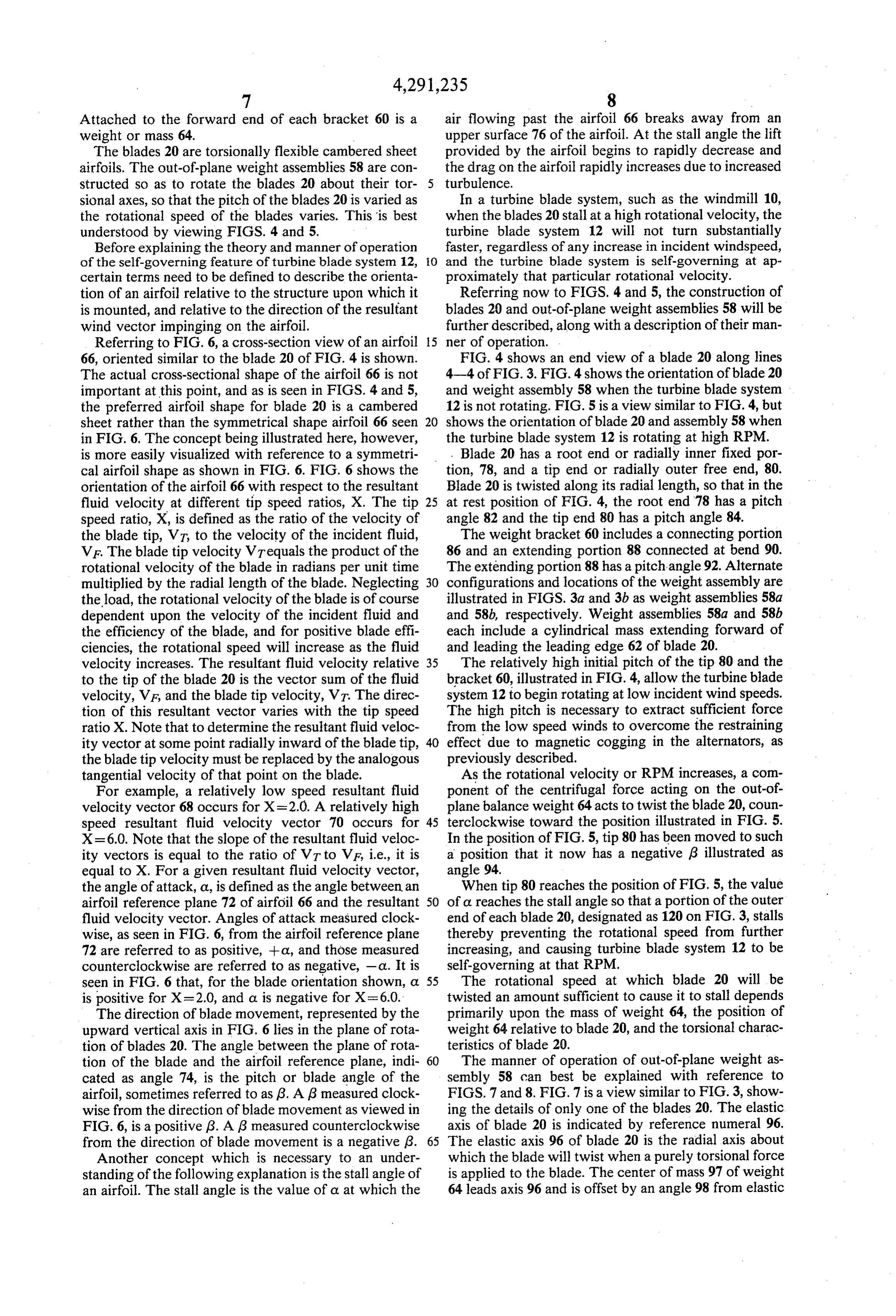
Page 12
axis 96. The centrifugal force acting on weight 64 is points, e.g. between inner end 78 and outer end 80, the represented by vector 100. Vector 100 can be resolved blade is torsionally flexible.
into two component vectors 102 and 104. Vector 102 The out-of-plane weight means 58 is attached to the acts parallel to axis 96 of blade 20 and is opposed by a continuously torsional blade 20 for continuously vary corresponding tensile force in blade 20. 5 ing the pitch of the blade 20 as the rotational speed of Referring now to FIG. 8, the vector 104 is illustrated the turbine blade system 12 is varied. The pitch is con as it would appear when viewed along line 8-8 of FIG. tinuously varied between a zero pitch variation at fixed 7. Vector 104 lies in a plane parallel to the plane of end 78 and a maximum pitch variation adjacent out-of rotation 106 of the elastic axis 96 of blade 20. The center plane weight 58, for a given variation of the rotational of mass 97 of weight 64 is forward of plane 106 and is 10 speed of the turbine blade system 12. offset an angle 108, about elastic axis 96, from plane 106. By "continuously varied' it is meant that the varia Vector 104 can itself be resolved into two component tion in pitch differs along the radial length of blade 20 vectors 110 and 112. Vector component 110 intersects for a given variation of the rotational speed of the tur elastic axis 96. Vector component 112, however, acts bine blade system 12. That variation in pitch continu perpendicular to imaginary line 114 between axis 96 and 15 ously increases from a zero value at fixed end 78 to a center of mass 97. maximum value adjacent out-of-plane weight 58. It is vector component 112 which acts to torsionally In a slightly modified version of the turbine blade rotate blade 20 as the rotational velocity of the blade system 12, a radially inner portion of blade 20 could be increases. The torque, acting to twist blade 20, is equal relatively rigid compared to the remainder of the radial to the force represented by vector 112, multiplied by 20 length of the blade 20. In such an embodiment the blade the distance between axis 96 and center of mass 97. 20 would be described as being continuously torsionally The force represented by vector 112 is equal to the flexible between free end 80 and a radially inner point centrifugal force acting on mass 64, multiplied by the on blade 20, said radially inner point being intermediate sine of angle 98, multiplied by the sine of angle 108. The of fixed end 78 and free end 80. The weight means 58 magnitude of vector 112 will, therefore, be a very small 25 would then be a means for continuously varying the portion of force vector 100 and the importance of using pitch of the blade 20 between a maximum variation blades that are highly flexible in torsion can readily be adjacent weight means 58 and a smaller variation at said seen. In general, since the magnitude of vector 112 is radially inner point for a given variation of the rota proportional to the centrifugal force vector 100, the tional speed of turbine blade system 12. With the weight change in the pitch of the blade 20 will be proportional 30 means 58 attached to a radially outer location on blade to the square of the RPM. 20 near the free end 80, the pitch of blade 20 would be The pitch change schedule can be tailored, within continuously varied along substantially the entire radial certain bounds, by varying the size and location of the distance between free end 80 and said radially inner weight, the initial blade tip angle 84, and the initial pitch point.
weight angle 92. In addition, the torsional characteris 35 In a preferred embodiment, the blade 20 is a cam tics of the blade 20 can be varied with changes in thick bered sheet airfoil. A significant characteristic of this ness, tip and hub chord and taper schedule. type of blade construction is that it does not form a A blade twist schedule is shown in FIG. 9. The hori closed section, or torque box. This coupled to the fact zontal axis represents the position on blade 20, and the that the blade 20 is unrestrained at its radially outward vertical axis represents the pitch of the blade 20 at its 40 end 80 gives the blade a high degree of torsional flexibil various positions. Line 116 represents the pitch of blade ity even though it is rigidly attached at its radially in 20 at rest. Line 118 represents the pitch of blade 20 at a board end 78. The present invention takes advantage of high rotational speed. Without such a pitch system, the this characteristic through the addition of the out-of initial tip angle 84, would have to be fairly small, for plane balance weight 58 attached off the leading edge example in the neighborhood of 5, to ensure that the 45 62 of the blade. The fact that the pitch weight 58 is blade would still be at a favorable angle of attack at inclined out of the rotor plane (see FIG. 4) causes it to normal operating speeds. With the pitch system, tip produce a force or torque, increasing with rotational angle 84 can initially be relatively high in the range of speed, that tends to rotate the weight back into the approximately 10-15, without significant adverse ef. plane of the rotor. The combination of the out-of-plane fect to the blades' performance at operating speeds. 50 weights 58 and the torsionally flexible blades 20 results This has a very advantageous affect upon start-up wind in a windmill rotor system which gives changes in blade speed for the rotor. pitch with changes in rotational speed and, yet, in In summary, the variable pitch concept of the turbine which all joints are rigid.
blade system 12 may be described as follows. Each In addition to functioning as a blade pitch variation blade 20 includes the radially inner fixed end 78 and the 55 means as just described, the out-of-plane weight assem radially outer free end 80. The blade 20 is continuously bly 58 solves the problem of torsional flutter in single torsionally flexible between the fixed end 78 and the surface airfoils. Since the elastic axis 96 of the thin sheet free end 80. airfoils 20 is behind the aerodynamic center of the air By "torsionally flexible' it is meant that the blade 20 foil, and at or behind the center-of-gravity of the airfoil, is sufficiently flexible that its pitch may be varied, by 60 there is a tendency for the blades 20 to flutter as the use of the out-of-plane weight means 58 to torsionally rotational speed increases. Flutter in this case is a self twist the blade 20 itself, an amount sufficient to signifi sustaining torsional vibration of the blades 20 in which cantly effect the aerodynamic characteristics of the the angle of attack varies above and below a nominal blade 20. For example, the pitch may be varied until the value at relatively high frequency, and in such a way as blade 20 stalls, thereby causing the turbine blade system 65 to decrease the aerodynamic performance of the turbine 12 to be self-governing. blade system and cause high structural loads. The for By "continuously' torsionally flexible it is meant that ward location of the out-of-plane balance weight 64 at any point along the blade 20 between the indicated serves to move the center of gravity well ahead of the
Page 13
elastic center 96 of the blade 20, thereby raising the turbine blade system, said pitch being continuously flutter speed above the operating range of the windmill varied between a zero pitch variation at said fixed system. end and a maximum pitch variation adjacent said Thus, the windmill of the present invention is well weight means for a given variation of said rota adapted to obtain the objects and advantages men tional speed of said turbine blade system; tioned, as well as those inherent therein. While pres wherein said weight means includes a mass with cen ently preferred embodiments of the invention have been ter of mass thereof leading an elastic axis of said described for the purpose of this disclosure, numerous blade so that said turbine blade system operates changes in the construction and arrangement of parts free from flutter, and with said center of mass lo can be made by those skilled in the art, which changes O cated out of a plane of rotation of said elastic axis of are emcompassed within the spirit of this invention as said blade so that a component of a centrifugal defined by the appended claims. force acting on said mass acts to twist said blade What is claimed is: about said elastic axis to vary the pitch of said 1. A variable pitch turbine blade system, comprising: blade.
a blade, including a radially inner fixed end and a 15 8. Apparatus of claim 7, wherein said weight means is radially outer free end, said blade being continu further characterized as being attached to a radially ously torsionally flexible between said free end and outer location on said blade and as being a means for a radially inner point on said blade, said radially continuously varying said pitch of said blade along inner point being intermediate of said fixed end and substantially its entire radial length. said free end; and 20 9. Apparatus of claim 8, wherein said center of mass an out-of-plane weight means, attached to said blade, is located forward of said elastic axis, so that said pitch for continuously varying a pitch of said blade in is decreased as the rotational velocity of said turbine response to a variation in rotational speed of said blade system is increased.
turbine blade system, said pitch being continuously 10. Apparatus of claim 9, wherein said pitch of said varied between a maximum variation adjacent said 25 blade is oriented at a relatively high positive angle along weight means and a smaller variation at said radi a radially outer portion of said blade when said turbine ally inner point for a given variation of said rota blade system is not rotating.
tional speed of said turbine blade system; 11. Apparatus of claim 10, wherein said blade and wherein said weight means includes a mass with a said weight means are constructed so that at a predeter center of mass thereof leading an elastic axis of said 30 mined rotational velocity the pitch of the radially outer blade so that said turbine blade system operates end of said blade is decreased to a value sufficient to free from flutter, and with said center of mass lo stall the outer end of said blade and cause said turbine cated out of a plane of rotation of said elastic axis of blade system to be self-governing at approximately that said blade so that a component of a centrifugal predetermined rotational velocity. force acting on said mass acts to twist said blade 35 12. Apparatus of claim 7, 8, 9, 10, or 11, wherein said about said elastic axis to vary the pitch of said blade is a cambered sheet blade.
blade. 13. A windmill, comprising:
2. Apparatus of claim 1, wherein said weight means is a shaft;
further characterized as being attached to a radially a turbine blade system;
outer location on said blade and as being a means for 40 first and second permanent magnet alternators, each continuously varying said pitch of said blade along of said alternators including a multiple pole stator substantially the entire radial distance between said free fixedly mounted on said shaft and a multiple mag end and said radially inner point. net permanent magnet structure rotatably mounted 3. Apparatus of claim 2, wherein said center of mass coaxial with said stator, said turbine blade system is located forward of said elastic axis, so that said pitch 45 being connected to said magnet structures to rotate is decreased as the rotational velocity of said turbine therewith, the poles of said stator of said second blade system is increased. alternator being angularly offset from the poles of 4. Apparatus of claim 3, wherein said pitch of said said first alternator and wherein the magnets of said blade is oriented at a relatively high positive angle along magnet structures of said first and second alterna a radially outer portion of said blade when said turbine 50 tors are aligned in axial rows so that only one of blade system is not rotating. said first and second alternators can have the poles 5. Apparatus of claim 4, wherein said blade and said of its stator radially aligned with the magnets of its weight means are constructed so that at a predeter magnet structure at any given time. mined rotational velocity the pitch of the radially outer 14. Apparatus of claim 13, wherein the magnets of end of said blade is decreased to a value sufficient to 55 each of said axial rows are further characterized as stall the outer end of said blade and cause said turbine being oriented so that magnet ends facing the stators all blade system to be self-governing at approximately that have the same magnetic sign.
predetermined rotational velocity. 15. Apparatus of claim 13, further comprising a third 6. Apparatus of claim 1, 2, 3, 4 or 5, wherein said alternator, the poles of said third alternator being angu blade is a cambered sheet blade. 60 larly offset from the poles of said second alternator so 7. A variable pitch turbine blade system, comprising: that only one of said first, second and third alternators a blade, including a radially inner fixed end and a can have the poles of its stator radially aligned with the radially outer free end, said blade being continu magnets of its magnet structure at any given time. ously torsionally flexible between said fixed end 16. Apparatus of claim 15, wherein the magnets of and said free end; and 65 said magnet structures of said first, second and third an out-of-plane weight means, attached to said blade, alternators are aligned in axial rows. for continuously varying a pitch of said blade in 17. Apparatus of claim 16, wherein the magnets of response to a variation in rotational speed of said each of said axial rows are further characterized as
Page 14
being oriented so that magnet ends facing the stators all means plus a maximum cogging force of said sec have the same magnetic sign. ond generating means.
18. Apparatus of claim 15, further comprising first, 25. The windmill of claim 24, wherein: second and third stator spacers, slidingly received on the poles of said stator of said second generating said shaft and fixed thereto, said first, second and third means are angularly offset from the poles of said stators being attached to said first, second and third stator of said first generating means. stator spacers, respectively. 26. The windmill of claim 25, wherein: 19. Apparatus of claim 13, wherein said turbine blade the poles of said rotors of said first and second gener system comprises: ating means are aligned in axial rows. a central hub, attached to said magnet structures; 10 27. The windmill of claim 26, wherein: a blade having a radially inner end, fixedly attached the rotor poles of each of said axial rows all have the to said hub, and a radially outer free end. same magnetic sign.
20. Apparatus of claim 19, wherein said blade is tor 28. The windmill of claim 24, wherein: sionally flexible. said first generating means includes an equal number 21. Apparatus of claim 20, wherein said turbine sys 15 of stator poles and rotor poles; and tem blade system further comprises an out-of-plane said second generating means includes an equal num weight attached to a radially outer location on said ber of stator poles and rotor poles. blade, so that the pitch of said blade is continuously 29. A windmill, comprising: a shaft;
decreased, with increasing rotational velocity of said 20 a turbine blade system;
turbine blade system, until a portion of said blade is first and second permanent magnet alternators, each stalled causing the turbine blade system to be self-gov of said alternators including a multiple pole stator erning at approximately the rotational velocity at which fixedly mounted on said shaft and a multiple mag said stall occurs.
22. Apparatus of claim 21, wherein a center of mass of 25 net permanent magnet structure rotatably mounted said weight leads an elastic axis of said blade, and is coaxial with said stator, said turbine blade system located forward of said elastic axis. being connected to said magnet structures to rotate therewith, the poles of said stator of said second 23. Apparatus of claim 13, 14, 15, 16, 17, 18, 19, 20, 21 alternator being angularly offset from the poles of or 22, wherein: said first alternator;
said first permanent magnet alternator includes an 30 wherein said turbine blade system includes: equal number of poles and magnets; and a central hub, attached to said magnet structures; said second permanent magnet alternator includes an a torsionally flexible blade having a radially inner equal number of poles and magnets. end, fixedly attached to said hub, and a radially 24. A windwill, comprising: outer free end; and a turbine blade system; 35 an out-of-plane weight attached to a radially outer first and second electrical generating means, each of location on said blade, so that the pitch of said said generating means including a fixedly mounted blade is continuously decreased, with increasing multiple pole stator and including a multiple pole rotational velocity of said turbine blade system, rotor rotatably mounted coaxial with said stator, 40 until a portion of said blade is stalled causing the said turbine blade system being connected to said turbine blade system to be self-governing at ap rotors to rotate therewith, said first and second proximately the rotational velocity at which said electrical generating means being arranged so that stall occurs.
at any given time only one of said first and second 30. Apparatus of claim 29, wherein a center of mass of electrical generating means can have its stator 45 said weight leads an elastic axis of said blade, and is poles and its rotor poles so relatively positioned as located
forward of said elastic axis.
Apparatus of claim 29 or 30, wherein:
to present a maximum cogging force for said one said first permanent magnet alternator includes an generating means, so that at any given time a total equal number of poles and magnets; and cogging force presented by said first and second electrical generating means is less than a total of a 50 saidequal second permanent magnet alternator includes an number of poles and magnets.
maximum cogging force of said first generating sk ck 2k sk k
Provenance
- Collection
- Cited prior art
- Original PDF
- patentimages.storage.googleapis.com →
- Filed
- 1979-02-26
- Pages
- 14
- Method
- pdftotext (the PDF's own text layer) + pdftoppm 300dpi page scans
- Source
- Google Patents bibliographic record
- Granted
- 1981-09-22
- Inventors
- Karl H. Bergey, Jr.; Michael L. S. Bergey
- Transcribed from
- patentimages.storage.googleapis.com →