patent · US5258697
Efficient permanent magnet electric motor
2 November 1993
Page 1 — bibliographic record
IIIHIIIHIII USOO5258697A
United States Patent (19) 11) Patent Number: 5,258,697 Ford et al. (45) Date of Patent: Nov. 2, 1993
54 EFFICENT
54 ESENENT MAGNET FOREIGN PATENT DOCUMENTS
75) Inventors: James R. Ford, Brea, Calif.; William 85566 5/1982 Japan. ESEYE". : A NEnds 73 Assignee: Varelux Motor Corp., Calif. OTHER PUBLICATIONS (21) Appl. No.: 780,968 Electro-Craft Corp Handbook 1978, pp. 2-66. 22 Filed: Oct. 23, 1991 Primary Examiner-Jonathan Wysocki 5ll Int. C. ............................................... H02P 7/00 57 ABSTRACT 52 U.S. C. ..... ... 318/498; 318/254;
310/156 An electric motor, of the type that includes a rotor with 58 Field of Search ............... 318/254, 138, 439, 498; permanent magnets and a stator with electromagnets, 310/154, 156, 180, 181 which operates at high efficiency to produce a high 8 ratio of mechanical power output to electrical power (56) References Cited input. During rotor G in A. direction (74, FIG.
2,816,240 12/1957 Zimmerman ........................ 310/156 alignment with the core of a "last" electromagnet 3,134,038 5/1964 Schilling ..... ... 310/156 (46A), while a second permanent magnet (44B) moves 3,482,156 12/1969 Porath ................................. 310/56 toward a position of alignment with the core of a "next' 4,223,263 9/1980 Hansen, Jr. et al. ... 310/156 X electromagnet (46C) which it is approaching. The last
1938; Kenwell
310/77 XX electromagnet (46A) is energized in a direction to ne 4,433,261 2/1984 Nashiki et al. ...................... 310/156 gate attraction of its core (50) for the first permanent 4,464,592 8/1984 Major .................................... 310/54 magnet (44A"). The next electromagnet (46C) is not 4,504,751 3/1985 Meier .............. ... 318/254 X substantially energized, so the attraction of the second 4,549,04 10/1985 Niimura et al. ..................... 310/156 magnet for the next electromagnet (46C) is due primar 4,553,075 l/1985 Brown et al. ... 3/2 ily to attraction of their cores in the absence of energiza 4,636,671 1/1987 Terada ............ ... 310/74 - 4,642,534 2/1987 Mitchell .............................. 318/38 tion of the next electromagnet. Thus, most electrical 4,661,736 4/1987 Kawada et al. ..................... power supplied to the electromagnets are to negate 4,678,954 7/1987 Takeda et al... ... 310/156 attraction between a permanent magnet and the last 4,698,538 10/1987 Yoshida ....... ... 36/175 electromagnet which the permanent magnet is moving 4,724,368 2/1988 Andrews.g. 38/439 away from. This allows most motor output torque to 4,769,567 9/1988 Kurauchi et al. ................... 39/156 arise from the attraction of permanent magnets for the 4,841,204 6/1989 Studer ............. ... 38/254 4,864,199 9/1989 Dixon .................................. 318/254 cores of unenergized electromagnets that the permanent 4,874,975 10/1989 Hertrich .............................. is magnets are approaching.
4,972,112 ll/1990 Kim ..................................... 310/181 5,030,868 7/1991 Suzuki et al. ....................... 310/156 9 Claims, 6 Drawing Sheets
Page 2
Drawing sheet — no readable text.
Page 3
Drawing sheet — no readable text.
Page 4
Drawing sheet — no readable text.
Page 5
Drawing sheet — no readable text.
Page 6
Drawing sheet — no readable text.
Page 7
Drawing sheet — no readable text.
Page 8
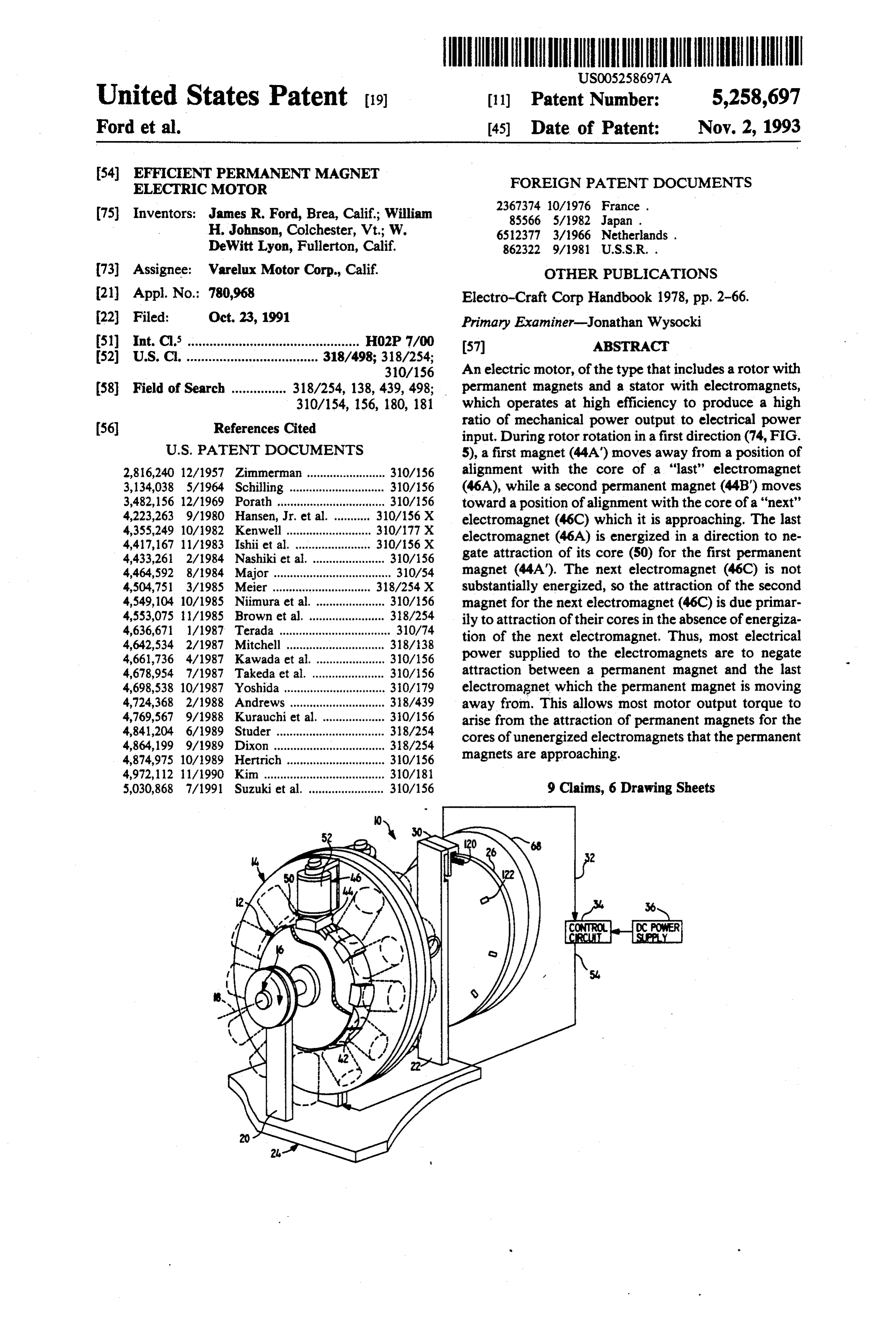
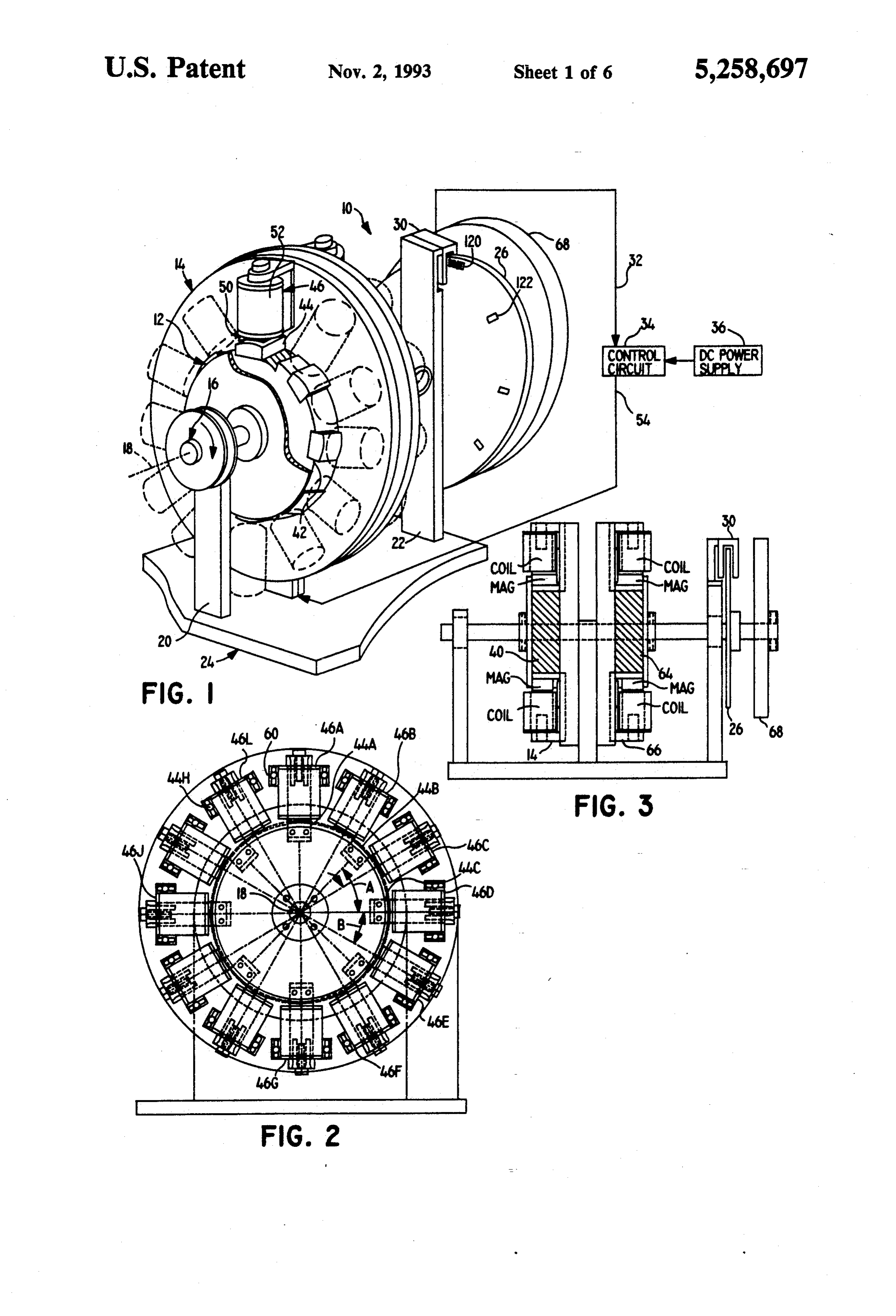
FIG. 4 is a simplified partial view of the motor of
EFFICIENT PERMANENT MAGNET ELECTRIC FIG. 2, with a permanent magnet in a center alignment
FIG. 5 is a view similar to that of FIG. 4, but with the
BACKGROUND OF THE INVENTION: 5 rotor turned 10' clockwise.
Permanent magnet motors where permanent magnets FIG. 6 is a view similar to that of FIG. 4, but with the rotor turned 20 clockwise.
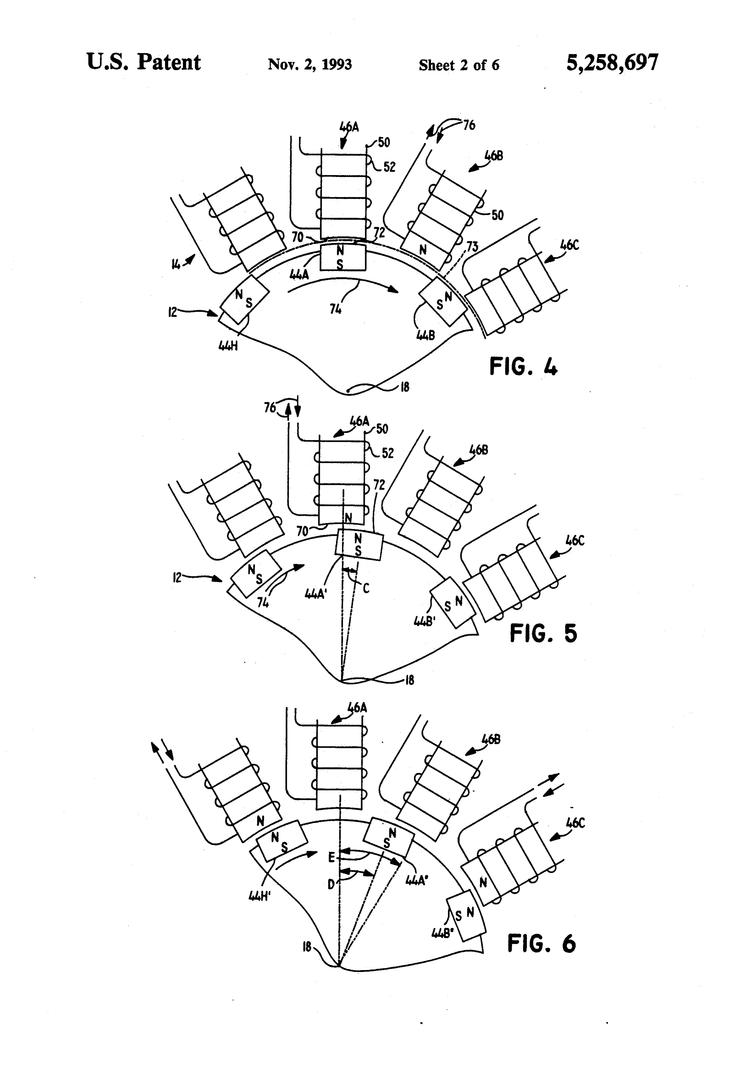
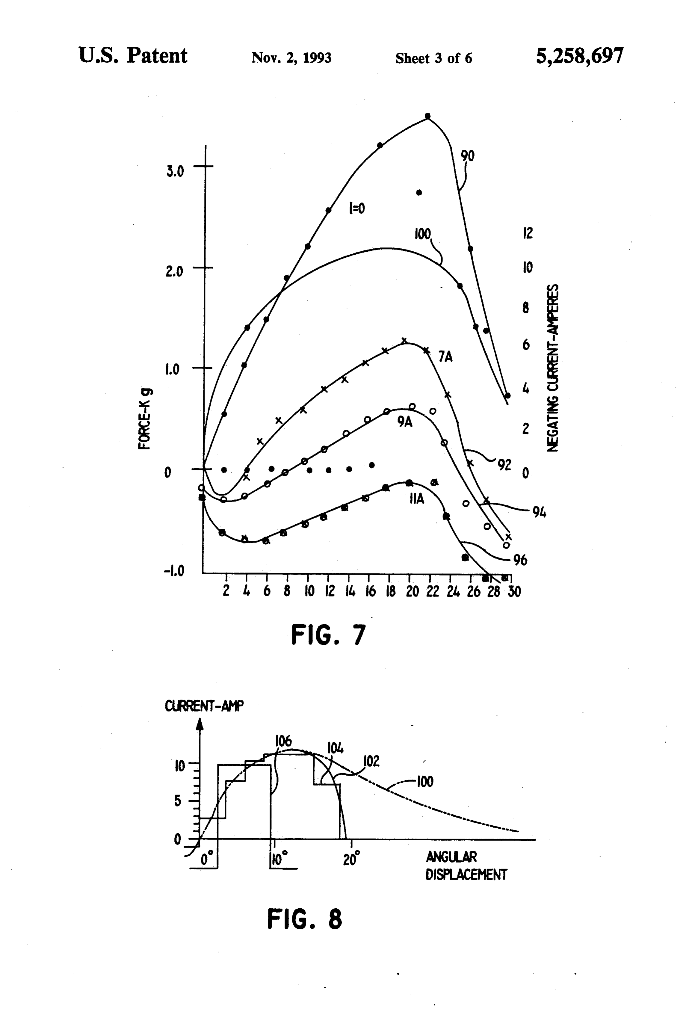
are spaced about the rotor and interact with electro FIG. 7 is a graph showing force versus displacement magnets spaced about the stator, provide efficient mo when a single magnet is moved linearly with respect to tors for energization from direct current sources such as 10 a single electromagnet, and also showing the variation batteries. In such motors, the electromagnets are ener in current required to produce a zero force, gized at high current levels to attract and/or repel the FIG. 8 is a graph showing variation in current with permanent magnets to produce a mechanical power rotor rotation for the motor of FIG. 1 in order to pro output. The considerable currents result in considerable duce substantially zero force between a permanent mag resistive losses and heat generation. Especially where 15 net and a last electromagnet.
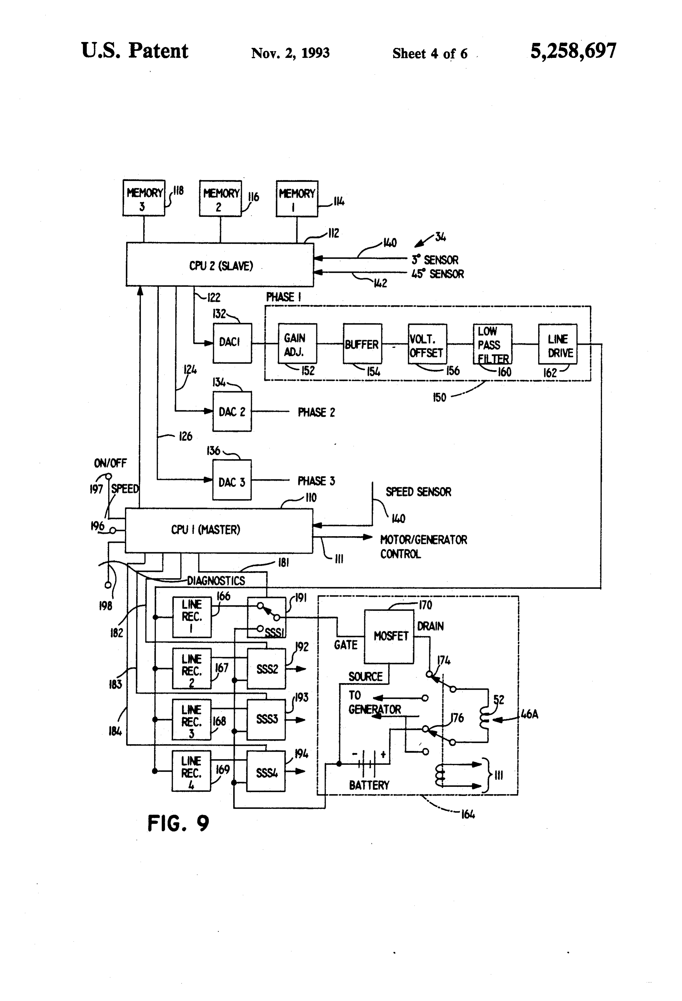
the motor is to be battery powered, as in electrically FIG. 9 is a primarily block diagram of the control powered automobiles, obtaining high efficiency in the circuit of the motor of FIG. 1.
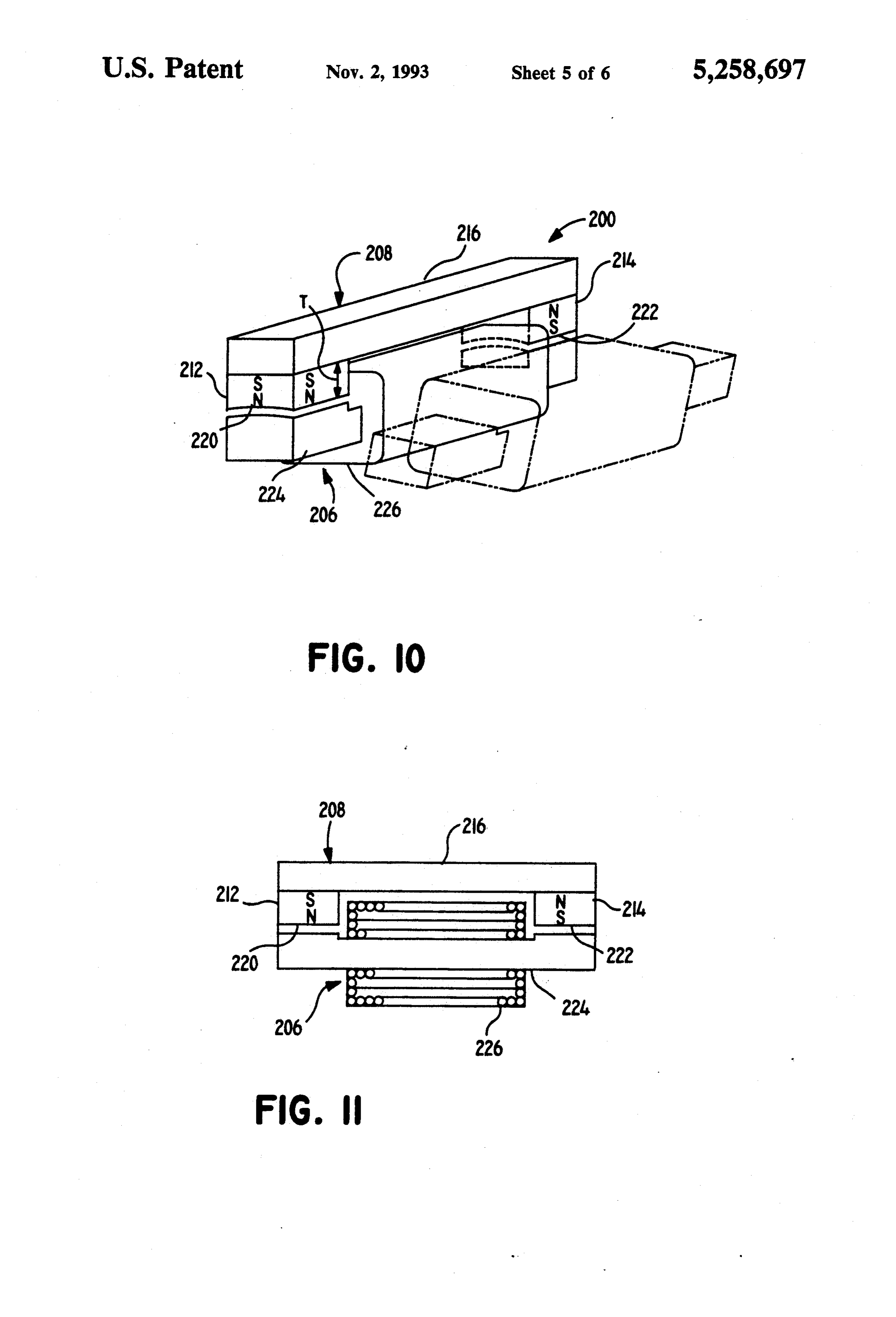
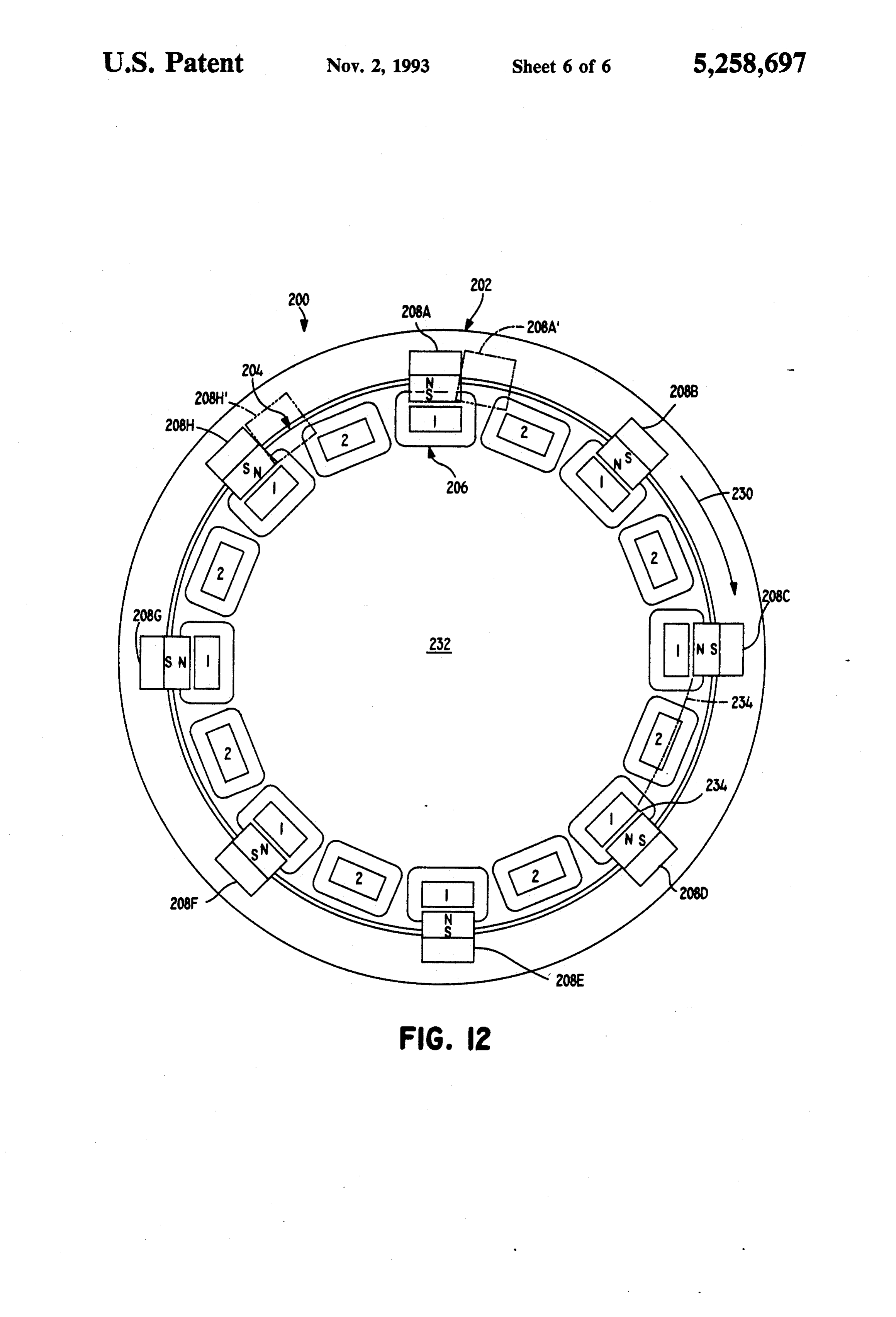
ratio of mechanical power output to electrical power FIG. 10 is a partial isometric view of a rotor-stator input is of great importance. A permanent magnet module of a motor constructed in accordance with motor which provided increased efficiency, would be 20 another embodiment of the invention. of considerable value. FIG. 11 is a sectional view of a permanent magnet SUMMARY OF THE INVENTION device and electromagnet of the module of FIG. 10. FIG. 12 is a front elevation view of a motor which
In accordance with one embodiment of the present comprises modules shown in FIG. 10.
invention, a permanent magnet motor and energization 25 DESCRIPTION OF THE PREFERRED method are provided, which results in high motor effi EMBODIMENTS ciency. At least during moderate load conditions, elec tromagnets are energized primarily to negate attraction FIG. 1 illustrates an electric motor 10 which includes to permanent magnets that are moving away from the a rotor assembly or rotor 12 and a stator assembly or electromagnets. Thus, when a first permanent magnetis 30 stator 14. The rotor has a shaft 16 that is rotatable about moving away from the core of a "last' electromagnet an axis of rotation 18 on bearings mounted on supports and a second permanent magnet is moving towards a 20, 22 of a support assembly 24. An index wheel 26 is "next' electromagnet, current is used primarily to ne fixed to the rotor shaft and passes across an index sensor gate the attraction of the first permanent magnet to the 35 30 which senses the rotational position of the rotor. The last electromagnet. Torque is obtained by the magnetic 32 output of the index sensor is delivered over a sensor line attraction of the second magnet towards the core of the nected to a control circuit 34. The control circuit is con next electromagnet. to a DC power supply 36 such as a group of The current applied to a last electromagnet (where batteries. The control circuit controls the delivery of the adjacent permanent magnet is moving away from it) 40 current from the power supply to the stator of the rotor, is preferably adjusted so the current varies to maintain a to The energize the motor so as to rotate it.
rotor includes a rotor body 40 and a group of largely zero net force between the core of the electro permanent magnet and the permanent magnet moving away from the rotor andmagnets 44 spaced about the periphery of it. The permanent magnet is of a material such as Nd-B- electromagnets 46 thatTheinteract its body. stator 14 includes a group of with the permanent
Fe (neodymium-boron-iron) which has a greater coer 45 magnets on the rotor. Each permanent cive force (the force required to demagnetize the mag a core 50 of ferromagnetic material suchmagnet includes net) than its induction, so the permanent magnet cannot and a winding 52 that is connected through wires steel as silicon
demagnetize itself. This allows a permanent magnet of cable 54 to the control circuit. The control circuit ener small thickness to be used, which results in requiring gizes selected electromagnets (the windings thereof) in less current flow to the last electromagnet to negate the 50 a manner to be described below, which causes rotation attractive force. Open magnetic circuit and closed mag of the rotor so it can produce a considerable mechanical netic circuit arrangements are described, with the output.
closed circuit arrangement placing both poles (north As shown in FIG. 2, the particular motor has eight and south) of each electromagnet adjacent to the corre PMs (permanent magnets) 44A-44H which are uni sponding poles of each permanent magnet. 55 formly spaced about the rotor axis 18 along the periph The novel features of the invention are set forth with ery 60 of the rotor (ofits rotor body). Thus, the PMs are particularity in the appended claims. The invention will spaced apart by an angle A of 45". The motor has be best understood from the following description when twelve EMs or electromagnets 46A-46L that are also read in conjunction with the accompanying drawings. uniformly spaced about the axis 18 so they are spaced BRIEF DESCRIPTION OF THE DRAWINGS apart by an angle B of 30'. As shown in FIG. 3, the particular motor includes two rotors 40, 64 and two
FIG. 1 is a partial isometric view of a motor con corresponding stators 14, 66, and also includes a structed in accordance with one embodiment of the flywheel 68.
present invention. Reference is made to FIGS. 4-6 which indicate the FIG. 2 is a front elevation view of the motor of FIG. 65 manner in which the motor is energized. With the rela 1. tive positions of the rotor and stator 12, 14 as shown in FIG. 3 is a partially sectional side view of the motor FIG. 4, it can be seen that a first PM 44A is in a center of FIG. 2. alignment position with the core 50 of the electromag
Page 9
net 46A. The core 50 has a face 70 lying close to the the first PM has moved to the position 44A". Since the path of the faces 72 of the PMs with only a small air gap first PM at 44A" is still moving away from the first between them at an imaginary interface circle 73. At the electromagnet 46A, a current can continue to be applied orientation of FIG. 4, the first electromagnet 46A (the to the first electromagnet to negate the backward pull winding 52 thereof) does not carry any current, as such on the first PM 44A". However, if there is any current current does not help rotation. A second PM 44B lies through the first electromagnet, it should be small, to half-way between the second and third electromagnets avoid substantial repulsion of the PM at 44.H" which is 46B and 46C. If no current flowed through either elec approaching the first electromagnet 46A. It also can be tromagnet 46B or 46C, then the permanent magnet 44B seen that the second PM 44B" has moved past a position would be equally attracted to the cores of both electro 10 of alignment with the third electromagnet 46C (which it magnets and there would be no net torque tending to attained after 15 of rotor rotation from the position of rotate the rotor in the direction of arrow 74. Applicant FIG. 4). As a result, the third electromagnet 46C is the flows a current, indicated by arrows 76, through the "last' electromagnet for the PM at 44B', and such last windings of the second electromagnet 46B to magnetize electromagnet 46C is energized to negate the backward the core 50 of that electromagnet to allow the second 15 attraction of the second PM 44B'. In the manner de PM 44B to move away from the core of the electromag scribed above, each "last' electromagnetis energized to net 46B. negate attraction for the PM moving away from it (at In accordance with present invention, the amount of least until the approaching permanent magnet comes current 76 passed through the second electromagnet close), while the "next' electromagnet which the PM is 46B is only that which is required to create a substan 20 approaching, is substantially unenergized and torque is tially zero force between the second PM 44B and sec provided by attraction of the PM for the core of the ond electromagnet 46B. With substantially no force unenergized next electromagnet. The angle E of 30 is dragging the second PM 44B backward (opposite to the angle to which the first PM 44A" must be turned to arrow 74) the main force on the second PM 44B is be at a center alignment position with second electro towards the core of the third electromagnet 46C. The 25 magnet 46B.
third electromagnet 46C is not energized (no current In a simpler notation, it is possible to identify the flows through its windings) so the only force between three electromagnets 46A-46C as "EMA, EMB, and the PM 44B and electromagnet 46C is the magnetic EMC', and to identify the permanent magnets 44A and attraction of the PM 44B for the "soft iron' core of the 44B as 'PM and PM2'.
third electromagnet 46C. Thus, the forces tending to 30 FIG. 7 illustrates the results of an experiment wherein rotate the rotor in the direction of arrow 74 are the a single permanent magnet was moved in a line away forces of attraction of PMs such as 44B for the cores of from a single electromagnet, this occurring several substantially unenergized electromagnets such as that of times, with a different constant current applied to the electromagnet 46C which the magnet 44B is approach electromagnet each time. The current was in a direction ing. Except when high loads are applied, as when an 35 to magnetize the core of the electromagnet to repel the electric car must rapidly accelerate or must move at permanent magnet. The variation in force of the perma high speed, most, (over 50 per cent) and preferably nent magnet with distance from its center alignment almost all (over 75 per cent) torque rotating the rotor position with the electromagnet, was measured. The arises from the attraction of some PMs towards the permanent magnet had a face area of one inch by one cores of substantially unenergized electromagnets that inch and was constructed of neodymium-boron-iron. the PMs are approaching. Most (over 50 per cent) and The electromagnet had a corresponding face, and in preferably almost all (over 75 per cent), of the current cluded 300 turns of wire. A first curve 90 shows the supplied to the motor at moderate loads is used to ne variation in force in kilograms on the vertical scale gate the backward force on those PMs that are moving versus the displacement in millimeters on the horizontal away from the core of a "last' electromagnet that the 45 scale, when the current was zero. The greatest force PM was just previously aligned with. occurred at a displacement of 22 mm which is about 85 FIG. 5 illustrates the motor of FIG. 4, after the rotor per cent of the width of the facing poles. A second 12 has rotated by an angle C of 10. As a result, the first curve 92 shows a situation when a constant current PM is at the position 44A" wherein it is moving away seven amperes was passed through the winding of the from the first electromagnet 46A and toward the second 50 electromagnet, the curve showing that this resulted in electromagnet 46B. The first electromagnet 46A can zero force at displacements of about 4.1 and 26.3 mm. therefore be considered to be the "last' electromagnet Curve 94 shows a situation when nine amperes and (the last one that the PM was aligned with) and the curve 96 shows a situation when eleven amperes, was second electromagnet 46B can be considered to be the passed through the coil. From these curves 90-96, ap "next" electromagnet (the one that the PM will next be 55 plicant has constructed the curve 100 which shows in alignment with). At this time, the first electromagnet approximately the amount of negating current that 46A will be energized as indicated by arrows 76 to make should pass through the electromagnet so there is sub its face 70 have a north magnetic pole of relatively low stantially zero force between the permanent magnet and intensity. The low north pole magnetic flux density the electric magnet as the permanent magnet moves produced at the face 70 of electromagnet 46A, by cur away from a position of alignment.
rent flow, is sufficient to substantially cancel the attrac FIG. 8 includes a curve 100 representing the varia tion between the north pole face at 72 of the first PM at tion in current to an electromagnet, with displacement 44A, and the core 50 of the first electromagnet. This of a permanent magnet therefrom, to achieve substan avoids a backward force on the PM 44A, so its attrac tially zero force between them, as the permanent mag tion for the core of the second electromagnet 46B can 65 net rotates on a rotor. However, in a real motor such as be used to turn the rotor. the one of FIGS. 1-6, as one permanent magnet moves FIG. 6 illustrates the motor after the rotor has turned away from an electromagnet, another permanent mag by an angle D of 20' from the position of FIG.4, so that net moves closer thereto. At a rotation angle at 22.5,
Page 10
the two permanent magnets (44A and 44H) are equally spaced 3 apart around the axis of rotation. It may be spaced from the core of the permanent magnet (46A). noted that the index wheel has markings 122 indicating Curve 102 represents a better variation of current with every 45 of rotor rotation. After each 3' of rotor rota angular rotation of the rotor (where 0 is where a per tion, the three memories 114-118 deliver a new signal manent magnet is aligned with the electromagnet to be 5 indicating the new level of current to a corresponding energized). It can be seen that the current falls rapidly at one of the three coils or electromagnets in a phase unit. an angular rotation of more than about 15' to avoid The detector (30 of FIG. 1) is of special design. The repulsion of the permanent magnet that is approaching output of a central infrared emitter is reflected back into the electromagnet. Although it is possible to provide an one of two infrared detectors depending on whether a analog variation of voltage to each electromagnet with 10 3' or a 45" slot (reflector) is in line with a narrow slit on angular rotation, the circuitry would be expensive and the side of the detector unit 30 facing the index wheel. result in considerable losses. The graph 104 represents The slave CPU2112 has three outputs 122-126 that an approximation to the curve 102, achieved by chang each represents the current to be delivered to one of the ing the voltage in steps, at angles of rotation of 3' each, three coils in a phase unit (there are four phase units). to approximately follow the analog curve 102. It can be 15 Each output is connected to a corresponding one of seen that the current level at 9" (which is 30 per cent of three DAC (digital analog converters) 132-136. The the total angle E of 30' between positions of alignment inputs to the slave CPU2112 includes a first input 140 of the magnet with two adjacent electromagnets) is which carries a pulse after every 3' of rotor rotation, greater than the current level at 3" (which is ten per which is obtained from one of the index sensors of de cent of the total angle). 20 tector 30 of FIG. 1. Another input 142 is a pulse that is The winding of each electromagnet acts as an induc delivered after every 45" of rotor rotation, which results tor that resists a change in current passing through it. If in the resetting of circuits in the slave CPU2112. Input the inductance is high, then it can be difficult to vary 140 is also used as a speed detector for load-speed con the current in the manner indicated by graph 104. FIG. trol by CPU1. The output of each DAC such as 132 is 8 includes another graph 106 which represents the ap 25 an analog signal which is delivered to a circuit portion plication of a single large voltage pulse to the winding 150 that operates as a set of operational amplifier com of an electromagnet to largely negate the attraction for ponents (designed to be supplied with plus and minus 15 the permanent magnet moving away from the electro volts) as such components are inexpensive and readily magnet. The voltage applied appears like graph 106, but available.
the current will have a significant rise and fall time. The 30 The first part 152 of the subcircuit 150 is a gain ad voltage at the beginning of a rise can be increased to juster 152 whose output is delivered to a buffer 154 raise the current faster. Tests by applicant on the coils which rejects extraneous signals. The output of the constructed by them, indicate that the time constants of buffer is delivered to a voltage offset circuit 156 which the coils are small enough that the current can be offsets the input voltage to take account of the fact that readily changed in several steps during each about 20 35 the MOSFETS to be used for coil current control later of turning, during rotation of the rotor at a relatively in the circuit require a threshold offset of approximately high speed such as twelve revolutions per second. The 3.1 volts. The output of offset circuit 156 is delivered to time aptitude and duration of voltage pulse application a low pass filter 160 which rejects high frequency noise relative to the position of the rotor, can be varied as the and whose output is delivered to a line driver or opera speed of rotor rotation varies. 40 tional amplifier 162. The output of the line driver 162 is FIG. 9 illustrates details of the control circuit which delivered to one of several line receivers 166-169. A can control the motor of FIGS. 1-6. The circuits in second circuit portion 164 operates at plus 24 volts to be clude two programmed CPU's (central processor units), consistent with the output of two series connected 12 CPU numbered 110 and CPU2 numbered 112. CPU1 is volt lead storage batteries. The output of the line driver used as a master control and CPU2 as a slave. Motor 166 is delivered to a solid state switch SSS1 191 which on/off and speed control are functions of CPU1 and the controls the input to an operational amplifier consisting phasing of electromagnets is the main function of of two parallel MOSFETs 170. The level of input volt CPU2. age at the gate of the MOSFETs controls the current Three memory segments 114-118 are attached to applied to the electromagnet coil 52 of electromagnet CPU2. Each memory segment 114-118 stores a "look 50 46A. The outputs of the other line drivers 167-169 pass up' table representing the current to be applied to a through solid state switches 192-194 and through cir particular coil during rotation of the rotor. Referring to cuits similar to portion 164, to energize the coils 52 of FIG. 2, it can be seen that the coils operate in four electromagnets 46D, 4.6G, and 46J, respectively. groups, called phase units, each of which includes three The motor can be operated in a generator mode coils, with the first group including coils of electromag 55 where the electromagnets are disconnected from the nets 46A, 46B and 46C. At any given time, the current driving MOSFETs and connected to battery charging applied to the first electromagnet 46A of the first group units. This is accomplished by means of the relay of three, is the same as the current applied to the first contacts 174 and 176. These are shown in the motor electromagnet 46D of a second group of three electro drive configuration, which would be the normally on magnets 46D, 46E and 46F (and the first electromagnets configuration. Activation of the relays by signals 111 46G, 46J of the other groups). Thus only three memo from the master CPU1 110, disconnects the driver cir ries or "look up' tables are required, one for each of the cuits and connects the recharging circuits. three coils in each phase unit. Each of the electromagnet coils 52 of the motor has a Referring to FIG. 9, memory 114 is a look up table dual control. When the solid state relay SSS1 191 con listing the current or voltage to be applied to the first 65 nects the line receiver 166 to the MOSFETs 170, cur coil of each phase unit, during each 3 of rotor rotation. rent through the coils is under control of the slave 3' was chosen because the index wheel (26 of FIG. 1) CPU2112. When SSS1 191 is in its alternate position, has markings 120 (in the form of slots or reflectors) the gates of the MOSFETs are brought to the same
Page 11
voltage as the source, thus shutting off the MOSFETs. need for reasonable air gap widths on the order of one As mentioned above, switches 191-194 control the de or a few millimeters. Thus, it appears likely that thinner livery of current to the coils of the first electromagnets magnets of high coercive strength such as Nd-B-Fe 46A, 46D, 46G and 46J of the four groups of three type would be preferred. As mentioned above, Nd-B-Fe electromagnets each. The second and third coils of each magnets first appeared in about 1986, and it appears phase group are controlled by similar solid state likely that magnets of this general type but with greater switches. At any one time, an entire phase group (of mechanical strength and/or greater flux density and three coils) can be turned on or off. The master CPU1 coercivity may be available in the future. Grain ori 110 has outputs (four of them shown as 181-184 in FIG. ented magnets, with the grains oriented at 15', 30 or up 9) which control the solid state switches. This allows 10 to 45' instead of the 0 currently available, may enable the master CPU1 to stop the flow of current through negating current to be applied during a shorter time any of the four coils 52 of the four electromagnets 46A, period for a given motor geometry. 46D, 46G or 46J during the time when current is flow FIGS. 10-12 illustrate a motor 200 constructed in ing through the other of the four coils. The same applies accordance with another embodiment of the invention, to the second and third coils of a given phase group. S which provides a "closed magnetic loop' arrangement Thus, during an entire rotor turn, a coil can be "taken and a 2:1 ratio of electromagnets to permanent magnets. out' along with the other coils in its phase unit when In the particular motor 200 (FIG. 12), the rotor 202 the motor is under low load conditions or one of the extends around the stator 204, this motor being designed coils is found defective by diagnostic circuits 198. This for use in the wheels of electric autos. The stator 204 provides for an ongoing "diagnostic' control of electro 20 includes eighteen electromagnets 206 while the rotor magnet behavior, thus preventing "lock up' conditions 202 includes nine permanent magnets 208A 208H ar when one phase group has an excessive "back torque' ranged as shown. The permanent magnets and electro due to coil failure. magnets are basically arranged in nine units, with each The master CPUI 110 can be adjusted for constant unit including two electromagnets labeled "1" and "2" speed at various loads by detecting changes in speed via 25 and one permanent magnet 208. This arrangement re the 3' sensor 140. Speed can also be controlled manually sults in fewer permanent magnets than the arrangement through input 196 to CPU1. The motor is turned on and of FIGS. 1-6, and results in a greater space between off through input 197. The direction of rotor rotation adjacent permanent magnets.
can be reversed by switching the phases, so in FIG. 4 FIG. 11 shows the construction of each electromag only electromagnet 46C is energized to negate, at the 30 net 206 and permanent magnet or permanent magnet position of FIG. 6 only electromagnet 46B is energized, device 208. Each permanent magnet 208 include two etc. permanent magnet elements 212, 214 of material of high As discussed above, applicant prefers to use perma induction and magnetic flux density such as Nd-B-Fe, nent magnets of Nd-B-Fe (neodymium-boron-iron), and a magnetic circuit bar 216 of material such as lami which have only recently (about 1986) been available. 35 nated silicon steel magnetically coupling the permanent Such permanent magnets have such high induction (so magnet elements. The permanent magnet elements are the grains are stiffly held) that they do not demagnetize arranged so one pole face 320 is of North magnetic themselves even when they have a small thickness be polarity, while the opposite pole face 222 is of South tween their opposite ends that have different magnetic magnetic polarity. The electromagnet 206 includes a polarities. Previous good magnetic materials such as the core 224 formed of "soft' magnetic material and a Alnico magnets, typically required a thickness between winding or coil 226 around its middle. The "soft' mag their opposite poles, of about two and one half times netic core can be constructed of conventional laminated their width and thickness in order to avoid self demag silicon steel, or of newer materials such as sintered netization. Applicant has found that the present mag phosphorus iron which has very low hysteresis. The nets of Nd-B-Fe retain their magnetism (an intensity of 45 arrangement shown in FIG. 11 provides space for fit about 4 kilogauss) even with very small thicknesses. ting the winding 226 between the permanent magnet Applicants originally used magnets with faces of one pole faces 220, 222. This arrangement may be referred inch width and one inch length, having a thickness of to as a closed magnetic circuit arrangement in that both one inch (two one-half magnets in series), and then used poles of the permanent magnet and of the electromag magnets of the same size except they had a thickness of 50 net are used.
one halfinch. Applicants also made tests using magnets Referring again to FIG. 12, after a 11.25' turn of the of one-quarter inch and one-eighth inch thick. Much rotor 202 in the direction 230, each permanent magnet thinner magnets have been used. Much thinner magnets then lies in a position such as 208A'. Each permanent have been difficult to use because of limited mechanical magnet 208A then lies halfway between a pair of elec strength in that they are more likely to break from the 55 tromagnets “1” and "2". With the rotor turning in the large forces encountered. Even with one eighth inch direction of arrow 230 about its axis of rotation 232, the thick magnets of Nd-B-Fe, applicant found that no self coil of the first electromagnet 206 labeled “1” will be demagnetizing occurred. Even smaller thicknesses are energized in an amount to negate backward attraction expected to result in stable permanent magnets. of the permanent magnet 208A, by the electromagnet There is an advantage in using thinner magnets, in “1”. (The coils of the other first electromagnets labeled that with the thickness of the magnets decreased by fifty "1" will be similarly energized.) The other electromag per cent, as from one inch to one halfinch, the magnetic net "2" is not energized, and the resulting torque tend field strength decrease by only about ten per cent. ing to rotate the rotor occurs due to attraction of the These magnets act largely like part of an air gap, and a permanent magnet 208A, for the ferromagnetic core of thinner magnet can reduce the equivalent air gap be 65 the unenergized second electromagnet "2". The advan tween the faces (72, 70) of the permanent magnet and tage of this arrangement is that the negating current the faces of the cores of the electromagnets they pass applied to electromagnet "1" can continue longer. That across, to provide large attraction forces despite the is, the negating current can continue while the perma
Page 12
9 O M ment magnet 208A' lies further from the electromagnet then "take out' a defective electromagnet by not pass "1' because such negating current will not have much ing a negating current thirough it.
effect on the approaching permanent magnet at 208H' Although particular embodiments of the invention since the magnet at 208H" is further away. have been described and illustrated herein, it is recog In a motor of the type shown in FIGS. 10-12 that nized that modifications and variations may readily applicants have designed, each permanent magnet ele occur to those skilled in the art, and consequently, it is ment such as 212 had a width and length of one inch and intended that the claims be interpreted to cover such a thickness T of one half inch, while the magnetic cir modifications and equivalents.
cuit bar 216 had a thickness of one halfinch and a length What is claimed is:
of about three inches. The diameter of the interface or O 1. An electric motor comprising: air gap circle 234 was one foot, and the poles of the a rotor having an axis of rotation and having a plural electromagnets were spaced apart by about 1.1 inches. ity of permanent magnets spaced about said axis; Three of such arrangements of permanent magnets and a stator having a plurality of electromagnets spaced electromagnets enable the production of a large starting about said rotor axis, each of said electromagnets torque at any initial rotational position of the rotor. 15 having a core of magnetic material and a coil, said Thus, the invention provides a motor of the type that electromagnetics being spaced relative to said per has permanent magnets (usually but not always on the manent magnets, so as said rotor rotates in a first rotor), which operates with high efficiency. This is direction, then during a predetermined angle of accomplished by energizing the electromagnets so the 20 rotor movement a first of said permanent magnets "last' electromagnet which a permanent magnet is moves away from a recently attained center align moving away from, is energized with a negating current ment position with a last of said electromagnets and which largely minimizes or eliminates backward forces a second of said permanent magnets moves toward on the permanent magnet, while torque tending to ro a soon-to-be-attained alignment position with a tate the rotor is obtained by the magnetic attraction of 25 next of said electromagnets; the permanent magnet for the core of the "next" elec a control circuit coupled to said electromagnets to tromagnet that the permanent magnet is approaching. energize them, said circuit being constructed so At times when especially high power is required, as during motor operation at moderate loads, said during acceleration or travel at high speeds, additional circuit does not substantially energize said next torque can be obtained by energizing the electromagnet 30 electromagnet as said second magnet moves so the "last' electromagnet actually repels the perma toward said alignment position therewith so most ment magnet with a large force and the "next" electro attractive force between said second magnet and magnet is energized to increase attraction for the per next electromagnet arises from the attraction of manent magnet. However, during operation at moder said second magnet toward said magnetic core of ate loads (e.g. an auto traveling at 30 mph which is 35 said next electromagnet, and said circuit energizes capable of travelling at over 60 mph, so the load is less said last electromagnet primarily to negate the than half maximum load), such additional currents to backward attraction of said first magnet for said create substantial repulsion and to enhance attraction magnetic core of said last electromagnet, so that may not be necessary, and most of the torque output of more of the torque arising from interactions of said the rotor is that which would be obtained merely by 40 last and next electromagnets with said first and completely negating backward attraction and employ second magnets tending to rotate said rotor in said ing no current for energization for forward attraction. first direction, arises from the attraction of said The negating current can be changed or varied as a second magnet toward said core of said next elec permanent magnet moves away from an electromagnet, tromagnet in its unenergized state than any repul so as to maintain a largely zero magnetic force between 45 sion of said first magnet from said last electromag the permanent magnet and last electromagnet. net plus any attraction of said second magnet for The permanent magnets can be thin compared to the said next electromagnet arising from energizing of dimensions of their faces, where magnets of high coer said next electromagnet.
cive strength are used. At low power levels, the number 2. The motor described in claim 1 wherein: of "units' (e.g. three electromagnets and two magnets 50 said circuit is constructed so the average repulsion or two electromagnets and one magnet) operating can between said first magnet and said last electromag be reduced to obtain higher efficiency. The amount of net during an angle of rotor rotation between a negating current can be varied to be somewhat greater position wherein said first magnet and last electro or less than that required for complete negation at any magnet are aligned and a position wherein said given relative position of the permanent magnet, so as 55 second magnet and next electromagnet are aligned, to adjust the speed of the motor for a given load. The is substantially zero.
sizes of the electromagnet coils can be relatively small 3. The motor described in claim 1 wherein: (thinner wire and fewer turns) compared to those of the ratio of the number of said electromagnets to the conventional motors, because only a low magnetic field number of said permanent magnets is 3 to 2, and is required from the coils to negate backward attraction. 60 said electromagnets and permanent magnets oper The computer that drives the motor, can sense the oper ate in groups that each includes three electromag ation of any unit (e.g. which includes three or two elec nets identified as EMA, EMB and EMC wherein tromagnets) to determine whether or not the electro EMB lies between EMA and EMB, and includes magnets are operating properly. For example, if the two permanent magnets identified as PM1 and ratio of voltage to current passing through the winding 65 PM2, where when PM1 of a group is in center of an electromagnet is above or below predetermined alignment with EMA then PM2 of the group lies ratios, this may indicate that there is an open circuit or approximately half-way between positions of cen short circuit in that electromagnet. The computer can ter alignment with EMB and EMC of the group;
Page 13
said control circuit is constructed so when said PM1 tending to rotate said rotor in a first direction in is in center alignment with said EMA, then only which said rotor is rotating, results from the level said EMB is energized considerably, with said of magnetic attraction of each closest permanent EMB being energized in a direction to largely ne magnet to the core of each next adjacent electro gate any attraction of PM2 and EMB. 5 magnet that said closest permanent magnet is ap 4. The motor described in claim 1 wherein: proaching that would exist in the absence of energi the ratio of the number of said electromagnets to the zation of said next adjacent electromagnet. number of said permanent magnets is 2 to 1. 8. The method described in claim 7 wherein: 5. The motor described in claim 1 wherein: each said permanent magnet moves 100 per cent of each of said permanent magnets has first and second 10 the alignment spacing angle between positions of opposite magnet poles of opposite magnetic polar center alignment with a last and a next electromag ity with each magnet pole having a magnet face, net core;
the core of each of said electromagnets has first and said step of energizing includes applying current to a second opposite core poles that each has a core last electromagnet which increases as the corre face, and said permanent magnets and cores are 15 sponding permanent magnet moves from a first arranged so said first magnet poles move closely position spaced ten per cent of the alignment spac facewise across said first core poles and said second ing angle away from alignment with the last elec magnet poles move closely across said second core tromagnet, and a second position spaced 30 per poles as said rotor turns. cent of the alignment spacing angle away from the 6. The motor described in claim 1 wherein: 20 last electromagnet.
said control circuit is constructed to change which of 9. An electric motor of the type which includes a said electromagnets are energized during a second rotor having a plurality of permanent magnets and a complete rotation of said rotor as compared to the stator having a plurality of electromagnets that each electromagnets energized during a previous first comprises a core of ferromagnetic material and a coil, complete rotation of said rotor. 25 with each permanent magnet and each core having at 7. A method for controlling energization of the elec- least one face lying on an imaginary interface circle, tromagnets of a motor during moderate load conditions, wherein the motor also includes a control circuit which wherein the motor has a stator assembly and a rotor is responsive to the rotation angle of said rotor to con assembly, wherein a group of permanent magnets are trol energization of said electromagnets, characterized mounted on a first of said assemblies and spaced in a 30 by:
circle thereon, and a group of electromagnets are said control circuit is constructed to energize each mounted on a second of said assemblies and spaced in a first electromagnet primarily during a time period circle thereon, where each electromagnet has a core of during which a first permanent magnet face that magnetically attractive material and an energizable coil, was most recently aligned with the electromagnet comprising: 35 core face of said first electromagnet is moving energizing each of a plurality of said electromagnets away therefrom, until a second permanent magnet during at least some of the time when the closest face that is approaching said first electromagnet permanent magnet is moving away from the last lies as close thereto as said first permanent magnet, adjacent electromagnet that said closest magnet lay with the energization of said first electromagnet adjacent to, with each said last adjacent electro- 40 during said time period being substantially in an magnet energized to substantially negate the mag amount to negate backward attraction of said first netic attraction between said closest permanent permanent magnet for said core of said first elec magnet and the core of said last adjacent electro tromagnet, during operation of said motor at mod magnet, so most motor torque which is produced erate load conditions.
by all permanent magnets and electromagnets, 45 k
Provenance
- Collection
- Cited prior art
- Original PDF
- patentimages.storage.googleapis.com →
- Filed
- 1991-10-23
- Pages
- 13
- Method
- pdftotext (the PDF's own text layer) + pdftoppm 300dpi page scans
- Source
- Google Patents bibliographic record
- Granted
- 1993-11-02
- Inventors
- James R. Ford; William H. Johnson; W. DeWitt Lyon; Varelux Motor Corp
- Transcribed from
- patentimages.storage.googleapis.com →