patent · US4691133
Iron-free rotary disk electrical machine
1 September 1987
Page 1 — bibliographic record
United States Patent (19) 11 Patent Number: 4,691,133 Mongeau 45) Date of Patent: Sep. 1, 1987 (54) RON-FREE ROTARY DISKELECTRICAL 4,514,653 4/1985 Batni ................................... 310/268 MACHINE 4,602,177 7/1986 Eckels et al. ......................... 310/57 75 Inventor: Peter P. Mongeau, Needham, Mass. Primary Examiner-Patrick R. Salce Assistant Examiner-D. L. Rebsch 73) Assignee: Electromagnetic Launch Research, Attorney, Agent, or Firm-Joseph S. Iandiorio; William Inc., Cambridge, Mass. E. Noonan (21) Appl. No.: 883,344 (57) ABSTRACT 22 Filed: Jul. 8, 1986 A rotary electrical machine having one or more rotor (51) Int. Cl. ....................... H02K 31/02; HO2K 1/22; elements comprising non-magnetic conductors extend HO2K 16/00 ing outwardly from the drive shaft axis and electrically 52 U.S. C. ..................................... 310/178; 310/114 coupled together at terminal portions, a device for pro 58) Field of Search ..... ... 310/112, 14, 126, 166, ducing excitation current through the rotor elements, 310/178, 206, 268 and one or more stator elements, interleaved between 56 References Cited the rotor elements, including elongated, non-magnetic electrical conductors extending outwardly with respect
3,407,320 10/1968 McLean .............................. 3O/14 3,548,231 12/1970 MacNab .............................. 310/78 33 Claims, 6 Drawing Figures
ExcTATION currxt
SOURCE 6
Page 2
Drawing sheet — no readable text.
Page 3
Drawing sheet — no readable text.
Page 4
Drawing sheet — no readable text.
Page 5
Drawing sheet — no readable text.
Page 6
pulses of one half to five seconds in duration at very
RON-FREE ROTARY DISK ELECTRICAL high voltages.
MACHINE It is a further object of the invention to provide such power pulses in the form of alternating current at virtu
FIELD OF THE INVENTION ally any desired voltage and without the need for col This invention relates to rotary electrical machines lectingIt is brushes in the output circuit thereof.
a further object of the invention to provide a and more particularly those capable of producing light, compact rotary electric machine which may be power pulses of about one half to five seconds in dura modular in construction and capable of operating at tion at a voltage of several thousand volts and also 10 high rotational speeds.
capable of operating continuously. It is a further object of the invention to provide such BACKGROUND OF THE INVENTION a rotary electric machine which is light and compact. It is yet a further object of the invention to provide a
Short bursts of electric power are conventionally rotary electric machine having rotor elements capable supplied by means of capacitors. Capacitors are suitable 15 of withstanding substantial centrifugal stresses, which for applications such as photo-flash units which involve may be constructed entirely without iron, in either the relatively small amounts of stored energy, ranging from stator or the rotor, and thus enable much of the avail several joules to several kilojoules. However, capaci able volume within the machine to be occupied by cop tors are too large and expensive for applications involv per or aluminum electrical conductors, to provide a ing several megajoules of stored energy. Such applica 20 more compact machine.
tions require energy supplies in which the energy is The invention features a rotary electrical machine derived from a storage inductor. Megajoule pulsed having one or more rotor elements, each having a plu power applications include electromagnetic launchers, rality of non-magnetic outwardly extending rotor con such as aircraft catapults and guns, percussion welding ductors carrying excitation current, and one or more machines, pulsed magnetic field metal forming ma 25 stator elements, interleaved between the rotor elements, chines, pulsed lasers, and X-ray and radar systems. Since including outwardly extending elongated, non-mag storage inductors dissipate their energy in a matter of netic electrical conductors.
seconds, they must be energized much more quickly In a preferred embodiment, serially connected rotor than capacitors; this requires rotary generators capable disks are provided having radial slots therein defining of delivering short bursts of high power. Conventional 30 excitation current paths, primarily toward and away generators cannot be forced to operate above their from the rotational axis of the machine. The stator ele rated output, even for short bursts, because power out ments include first and second sets of conductors lying within first and second planes respectively, and have put is limited by magnetic saturation of their iron cir toroidal cuits. In addition, only a small fraction of available 35 copper orwindings of spoke-like configuration. The thick aluminum rotor disks have a low resistivity, volume is used for conductors.
Two types of machines exist today which are capable high heat capacity and may be rotated at very high of high power pulse duty: homopolar generators, also rotational velocities.
called asynchronous generators, or Faraday disk gener A preferred embodiment utilizes structural hoops affixed to the peripheral disk portions to limit extreme ators, which are dc generators in which a conducting 40 radial centrifugal disk or cylinder rotates in a stationary magnetic field operating velocities. stresses during even higher rotational and compulsators. Homopolar generators operate at tor or a motor, and The machine can serve as a genera for pulse-duty or continuous-duty very low voltage and very high current, and require operation. For continuous-duty operation, the rotor contact brushes for their output current. They have the disks are preferably provided with forced flow cooling additional disadvantage of slow response to excitation 45 channels, and are laminated together via insulating control, and inability to use switching elements for disks.
output current control. Their usefulness is therefore restricted to loads having very low impedance. Com DISCLOSURE OF PREFERRED EMBODIMENT pensated pulsed alternators, also called compulsators, can operate at high voltage, but produce very short 50 tionOther objects, features and advantages of the inven will occur from the following description, of pre pulses of power which last only a fraction of one revo ferred embodiments and the accompanying drawings in lution, typically milliseconds. Existing generators, both which:
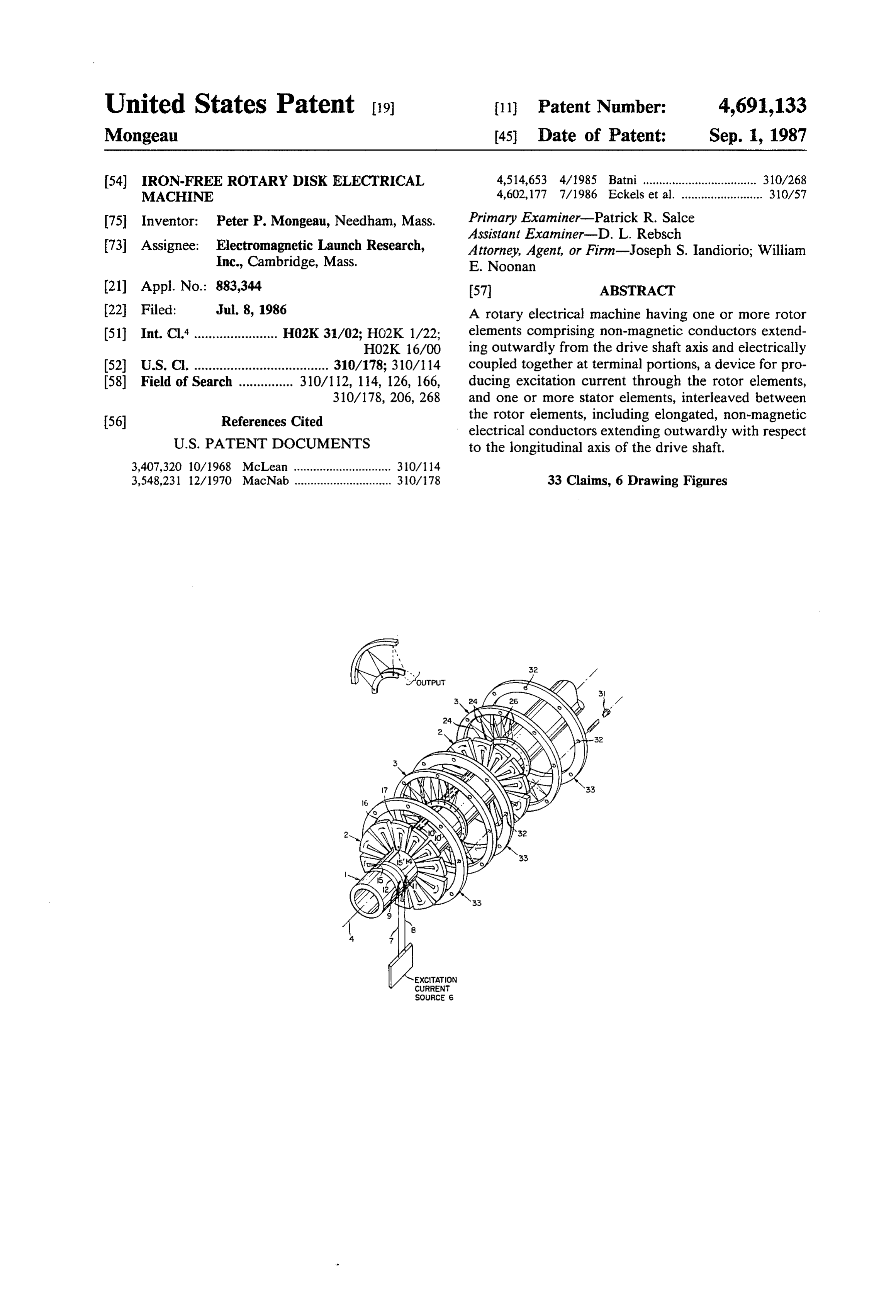
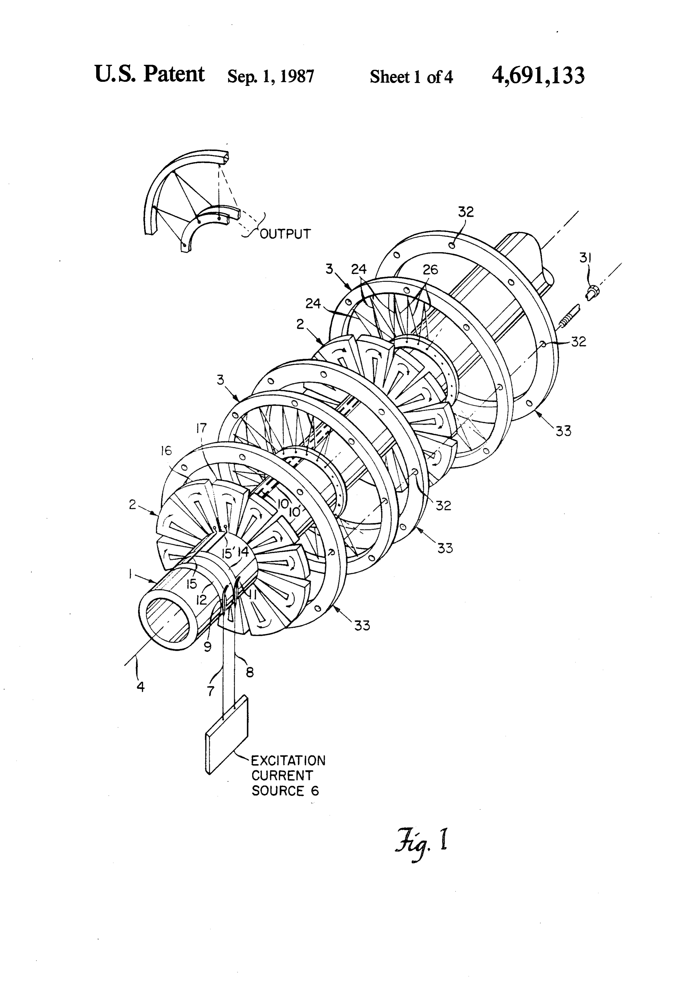
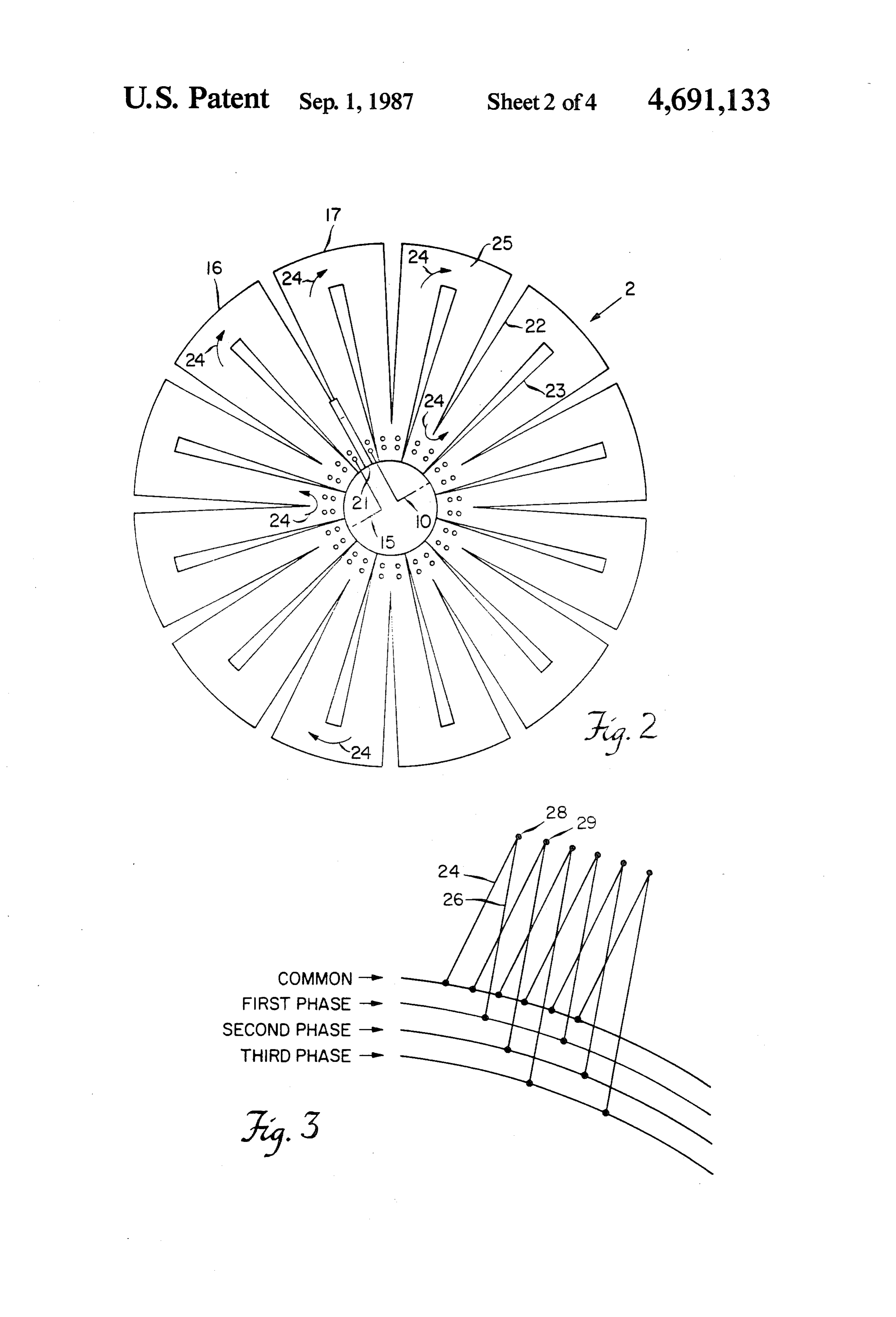
dc and ac, are designed for maximum efficiency and FIG. 1 illustrates an assembly view of the compo continuous operation, and incorporate an iron magnetic nents of the preferred embodiment; circuit to minimize the excitation current, and only a 55 FIG. 2 illustrates one rotor disk in greater detail; very small fraction of the available rotor and stator FIG. 3 schematically illustrates the manner in which volume is occupied by conductors, typically about one the stator windings are interconnected to form toroidal percent. Generators which do not use iron are certain winding configurations;
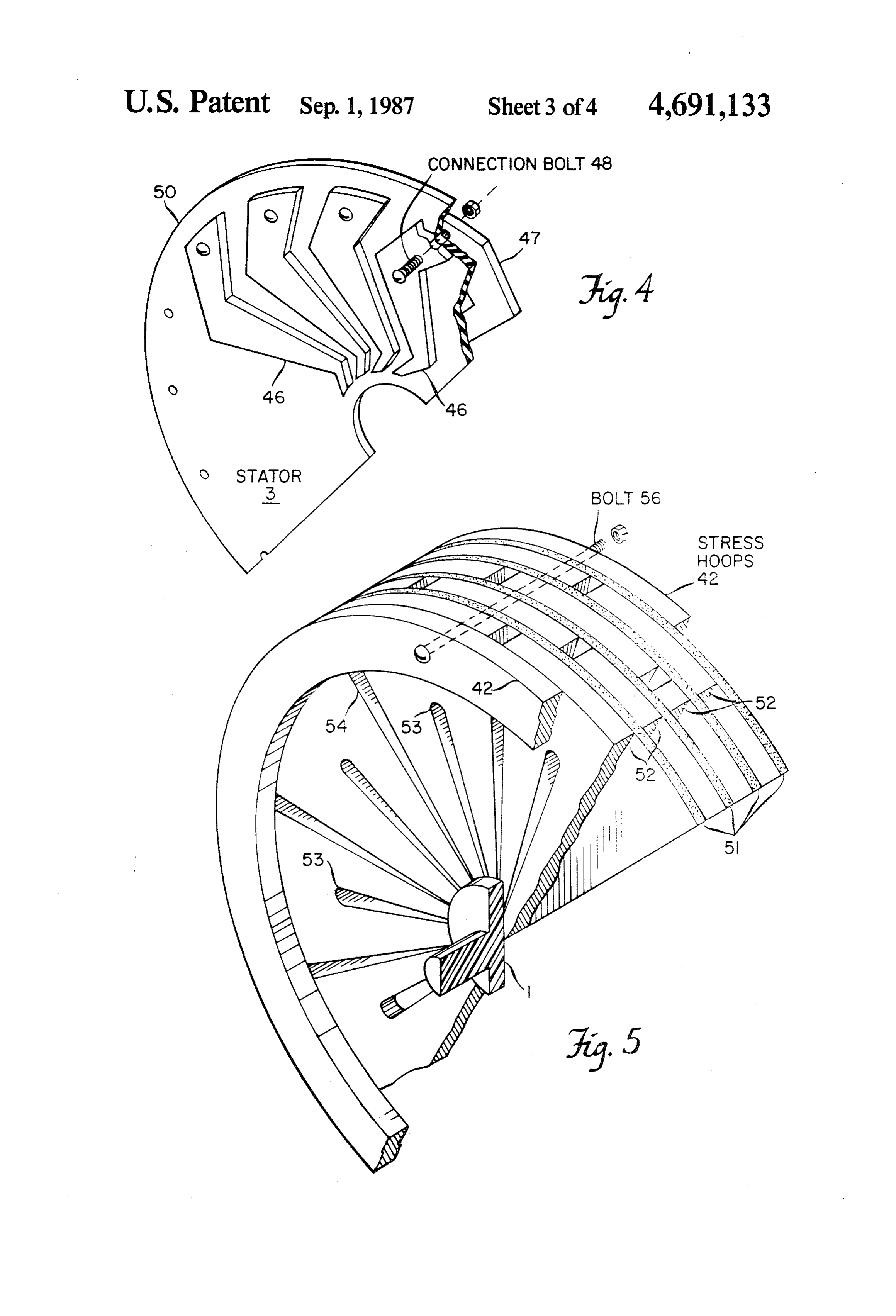
types of superconducting generators. Since supercon FIG. 4 illustrates a partial axonometric view of a ductors have no ohmic losses the excitation field can be 60 second form of a stator disk; produced easily without the use of iron. FIG. 5 illustrates a partial axonometric view of a SUMMARY OF THE INVENTION composite laminated rotor element; and
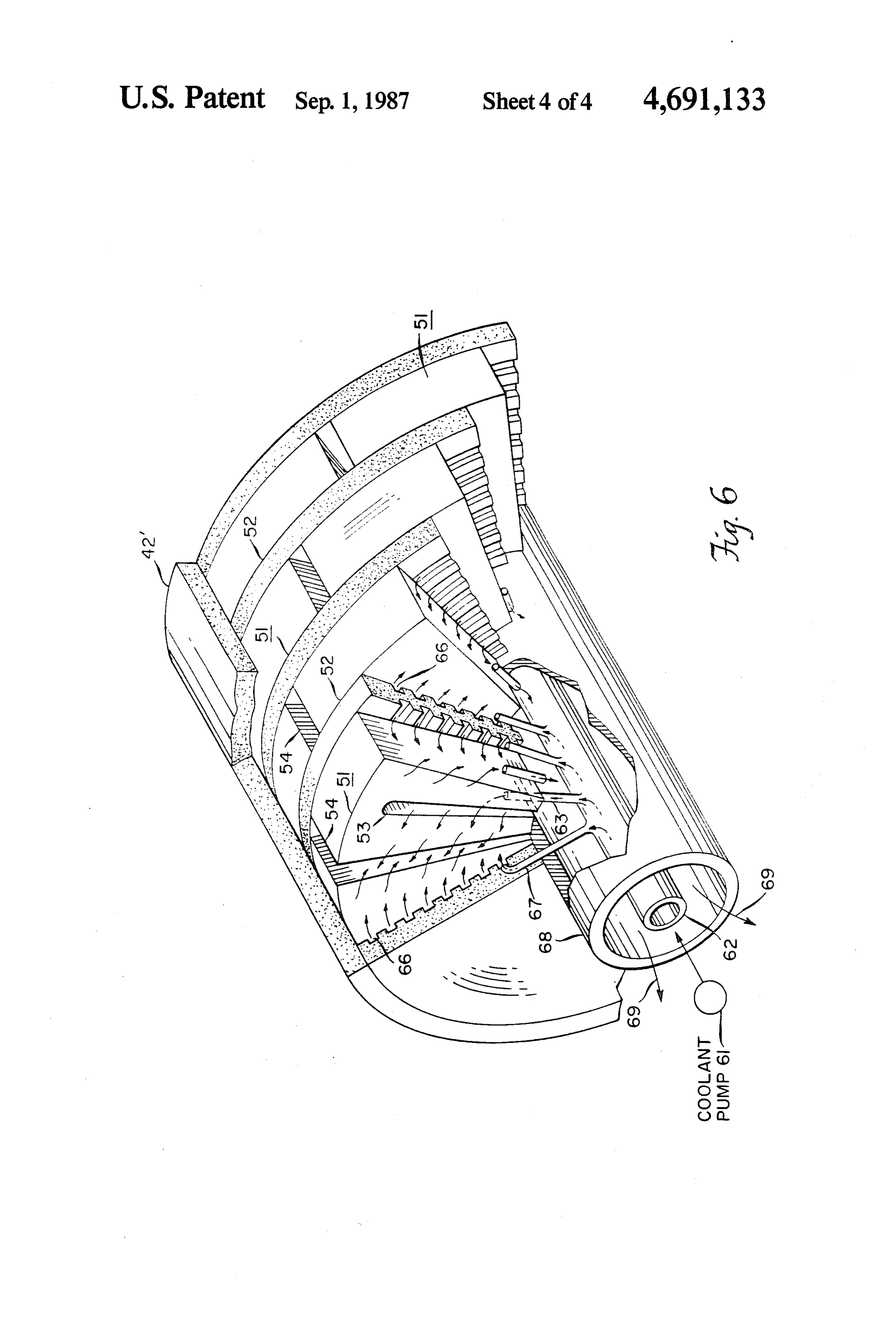
FIG. 6 illustrates a partial axonometric view of a
It is therefore an object of this invention to provide a cooled laminated rotor element.
rotary electrical machine capable of generating short 65 A preferred generator embodying this invention dif duration, high-voltage pulses. fers from conventional generators in that it uses about It is a further object of the invention to provide a 60 percent rather than one percent of its volume for rotary electrical machine capable of generating output conductors. This is accomplished by eliminating the
Page 7
conventional iron magnetic circuit. Elimination of iron pattern of course is repeated all the way around each increases the power required to generate a given excita stator and results in a set of toroidal poly-phase wind tion field intensity, and for this reason workers in the art ings for producing the high voltage poly-phase AC do not eliminate iron. However, the increased power output of the alternator. The conductors may be wire, cost of operating without iron is more than compen or stamped bars such as 46 and 47 illustrated in FIG. 4, sated by the increased utilization of space, so that the which are similar in geometry to those utilized in small overall efficiency of an iron-free machine is not very printed circuit motors, but substantially larger. They much lower than the efficiency of a conventional iron are electrically connected together by rivets or bolts 48 machine (about 95% compared to about 99%). to form a lap-winding of the required pole pitch. A The machine according to this invention, is also 10 non-conductive separator disk 50 is also shown. equally useful for continuous duty applications where As shown in FIG. 1, assembly drawbolts 31 pass maximum energy density is more important than maxi through apertures 32 of stator clamping rings 33 to form mum efficiency. the housing, coupling the stator disks 3 together. The In FIG. 1, drive shaft 1 has a plurality of rotor disks resulting multi-disk configuration provides good utiliza 2 rigidly affixed thereto, interleaved with stator disk 15 tion of the excitation field volume, which increases the elements 3 as illustrated. Input shaft 1 is driven by a thermal performance limit, by both increasing heat motor (not shown) and rotates about longitudinal axis 4. capacity and decreasing resistive heating, due to the A source of excitation current 6 is coupled to rotor disks high electrical conductivity and high heat capacity of 2 through leads 7 and 8, and brushes 9 and 11 which the thick copper or aluminum rotor disks. A preferable contact commutator rings 12 and 14. Ring 12 is electri 20 rotor disk configuration has an outside diameter of cally connected to the pie-shaped segment 16 of disk 2 about 120 cm, an inside diameter of 24 cm and a plate via lead 15, whereas ring 14 is coupled to the pie-shaped thickness of 2.5 cm. Thus a thick rotor disk plate, pref. segment 17 of disk 2 via 15" in a single disk machine. In erably made of aluminum alloy such as 6101-6, is pre a two rotor machine, segment 17 would be connected to ferred. It should be appreciated that this structure pro segment 16 of the second rotor and segment 17 of the 25 duces long tubular bundles of excitation flux, generated second rotor would be connected to ring 14 to thus more efficiently in an iron-free structure relative to the connect both rotors in series. The series connection of radial pole pattern of a conventional, cylindrical ma the second disk is indicated by leads 10 and 10", chine. Another beneficial result enjoyed by providing mounted upon shaft 1. All of the pie-shaped segments of thick slotted disk rotors, is that they can withstand the rotor disk are connected in series, due to the slotted 30 considerable radial centrifugal stresses without addi disk lobe configuration. Optionally, excitation current tional reinforcing structure, when driven at high rota may be inductively supplied without brushes, by means tional speeds, and thus high power output is enabled. of a separate excitation rotor provided with on-board Stress hoops 42 shown in FIG. 5, may be provided to rectifiers, the output thereof being utilized to excite the permit even higher rotational rotor speeds by reinforc other rotors mounted on the same shaft. Rotor disk 2 is 35 ing against extremely high centrifugal radial rotor shown in greater detail in FIG. 2 and insulator member forces. This is accomplished by the resulting tensile 21 is shown as one exemplary means to electrically stretching of the hoops, which may, if desired, be rig isolate pie-segment element 16 from element 17. Disk 2 idly affixed to a single disk rotor. Besides permitting of copper or aluminum, has radial slots 22 and 23 even higher speed rotation of the disks, optional stress formed therein to produce a series of current carrying 40 hoops 42, increase the moment of inertia for energy lobes defining a meandering current path around the storage.
disk, such current path being schematically represented In FIG. 5, individual rotor disks 51 form laminated by arrows 24. Thus, except for peripheral disk portions layers which are separated by insulating disks 52. The 25 and inner disk portions where the direction of cur aforesaid stress hoops 42 for providing added moment rent flow reverses, current flows within each rotor disk 45 of inertia and even higher speed operation are also element toward and away from drive shaft 2, substan shown, together with the aforesaid disk slots 53 and 54. tially perpendicular to the longitudinal axis 4 of the The entire laminated "sandwich' may be bolted to drive shaft. The rotor disks are preferably coupled in gether by bolts, one of which is schematically indicated series via leads 10 and 10 positioned within driveshaft at 56. It is important to note that the disk reinforcing 1, to minimize the excitation current. 50 stress hoops are made of non-conducting material. The The stator disk windings preferably resemble a bicy rotor disks in all described embodiments of the inven cle wheel in general configuration. As indicated in FIG. tion are preferably connected electrically in series, 1, the stator disks 3 have spoke-like conductors, lying in thereby reducing the required excitation current which two mutually exclusive planes which are substantially is preferably supplied through brushes. An advantage of perpendicular to longitudinal axis 4. Thus conductors 55 the laminated rotor is that the slotted disks can be stag 26 lying in a first plane intersect conductors 24 lying in gered, thereby eliminating the field asymmetry of a the second plane forming a small acute angle with re single slotted disk.
spect to the first plane, between 5 and 10 degrees. A The staggering of the slotted disks is clearly indicated small segment of spoke conductors 24 and 26 are sche in FIG. 6, illustrating another laminated rotor embodi matically illustrated in FIG. 3; spoke conductors 24 are 60 ment of the invention, useful for continuous operation, connected to spoke conductors 26 at peripheral points whereby a coolant, such as liquid nitrogen, is forced 28 and 29, thereby forming a series of toroidal windings, into the laminated rotor element to enable such continu or laps. Each of these two-spoke laps is connected at its ous operation. The radially extending rotor disk slots other extremity to current collectors in such a manner such as 53, delineate the excitation current path, and as to form a multi-phase lap winding. The connection 65 also function to distribute the coolant. A coolant pump shown schematically in FIG. 3 forms a three-phase 61 feeds liquid nitrogen, for example, under pressure to Y-connected lap winding, for example. However, more the inner tubular member 62, and numerous ducts such than three phases may be provided. This connection as 63 are provided to feed the coolant into each of the
Page 8
numerous radial slots 53. Insulating disks 52 have a 2. The rotary electrical machine as set forth in claim plurality of grooves such as 66 formed therein which 1 wherein said radially extending elongated conductors are coupled to the interior of coolant supply tube 62 via of said stator elements comprise toroidal windings. another plurality of feed ducts such as 67. The circula 3. The rotary electrical machine as set forth in claim tion of coolant within grooves 66 directly cools the 5 2 wherein said first and second planes intersect at an faces of the disk elements 51. The return flow path of angle of between 5 and 10 degrees.
the coolant is through slots 54 between the rotor lobes 4. The rotary electrical machine as set forth in claim and back into the space between the outside surface of 1 wherein said disks comprise thick solid, monolithic inner feed tube 62 and the inside surface of the outer bodies, having a high heat capacity, and said disks in tubular driveshaft member 67. Since the liquid nitrogen 10 clude channels therein for conducting a coolant there has absorbed considerable heat, it will generally exit through.
from hollow shaft 68 primarily in a gaseous state. It may 5. The rotary electrical machine as set forth in claim be noted that the staggering of the slotted disks also aids 2 wherein said disks comprise thick solid, monolithic in rendering the cooling effect more uniform. In the bodies, having a high heat capacity, and said disks in embodiment of FIG. 6, the stress hoops could take the clude channels therein for conducting a coolant there form of an elongated cylindrical element illustrated in through.
part at 42". 6. The rotary electrical machine as set forth in claim The presently contemplated best mode of practising 3 wherein said disks comprise thick solid, monolithic the invention is to construct the alternator in accor bodies, having a high heat capacity, and said disks in dance with the teachings of FIGS. 5 and 6. Laminated 20 clude channels therein for conducting a coolant there embodiments may utilize thinner conductive rotor disks through.
connected in series to minimize the excitation current. 7. The rotary electrical machine as set forth in claim The staggering of the disks clearly indicated in FIG. 6, 1 further including means for electrically coupling said also improves the rotational symmetry of the excitation 25 disks in series.
field, so that the peripheral circuit is closed, rather than 8. The rotary electrical machine as set forth in claim alternately opened as in a single disk. FIG. 6 clearly 2 further including means for electrically coupling said indicates the occupation of at least half of the interior disks in series.
volume of the electrical machine by the conductive 9. The rotary electrical machine as set forth in claim rotor elements. 30 4 further including means for electrically coupling said Typical excitation current for a pulse duty machine, disks in series.
with a 5-second rating of 27 MW and a 1-second rating 10. The rotary electrical machine as set forth in claim of 13.6 MW would be 40 kA at 6.32 volts, which 1 further including stress reducing hoops affixed to amounts to 253 kW. This assumes a single rotor disk peripheral portions of said rotor elements for reducing with all lobes connected in series. It is desirable to re-is radial stress due to high speed rotation of said rotor duce the current and increase the voltage at this same elements.
excitation power level, since the required brush area is 11. The rotary electrical machine as set forth in claim proportional to current and independent of voltage; 2 further including stress reducing hoops affixed to laminating the rotor from several thinner disks con peripheral portions of said rotor elements for reducing nected in series is the preferred approach. 40 radial stress due to high speed rotation of said rotor Although specific features of the invention are shown elements.
in some drawings and not others, this is for convenience 12. The rotary electrical machine as set forth in claim only as each feature may be combined with any or all of 4 further including stress reducing hoops affixed to the other features in accordance with the invention. peripheral portions of said rotor elements for reducing Other embodiments will occur to those skilled in the 45 radial stress due to high speed rotation of said rotor art and are within the following claims. elements.
What is claimed is: 13. The rotary electrical machine as set forth in claim 1. A rotary electircal machine comprising: 5 further including stress reducing hoops affixed to a drive shaft having a longitudinal axis of rotation; peripheral portions of said rotor elements for reducing one or more rotor elements mounted upon said drive 50 radial stress due to high speed rotation of said rotor shaft substantially perpendicular to the longitudinal elements.
axis thereof, said rotor elements comprising non 14. A substantially iron free rotary electrical machine magnetic disks of high electrical conductivity, each comprising:
said disk having radial slots therein forming a plu a drive shaft having a longitudinal axis of rotation; rality of current carrying lobes connected in series 55 one or more rotor elements mounted upon said drive and defining a meandering current path around shaft transverse with respect to the longitudinal said disk; axis thereof, each of said rotor elements comprising means for producing excitation current along said a plurality of non-magnetic rotor conductors ex meandering path within said disks in a transverse tending transversely with respect to said longitudi plane with respect to the longitudinal axis of said 60 nal axis and electrically coupled together in series; drive shaft; and means for producing excitation current through said a plurality of stator elements, adjacent said rotor rotor conductors; and elements, said stator elements comprising first and one or more stator elements, interleaved between said second sets of substantially radially extending elon rotor elements, said stator elements comprising gated electrical conductors oriented in first and 65 first and second sets of elongated, spoke-like, non second planes respectively, transverse with respect magnetic electrical conductors, each said set ex to the longitudinal axis of rotation of said drive tending transversely with respect to the longitudi shaft. nal axis of said drive shaft.
Page 9
15. The rotary electrical machine as set forth in claim radial stress due to high speed rotation of said rotor 14 wherein said elongated spoke-like conductors of said elements.
stator elements comprise toroidal windings lying in first 25. The rotary electrical machine as set forth in claim and second planes, for producing current flowing back 20 further including stress reducing hoops affixed to and forth, toward and away from said drive shaft. peripheral portions of said rotor elements for reducing 16. The rotary electrical machine as set forth in claim radial stress due to high speed rotation of said rotor 15 wherein said first and second planes intersect at an elements.
angle of between 5 and 10 degrees. 26. A substantially iron free rotary electrical machine 17. The rotary electrical machine as set forth in claim having a predetermined interior volume comprising: 14 wherein said rotor conductors comprise thick con 10 a drive shaft having a longitudinal axis of rotation; ductive bars for conducting said excitation current al one or more rotor elements mounted upon said drive ternately toward and away from said longitudinal axis, shaft transverse with respect to the longitudinal and further including means for electrically coupling axis thereof, each of said rotor elements comprising said rotor elements in series. a plurality of non-magnetic rotor conductors ex 18. The rotary electrical machine as set forth in claim 15 tending transversely with respect to said longitudi 15 wherein said rotor conductors comprise thick con nal axis and electrically coupled together at termi ductive bars for conducting said excitation current al nal portions thereof;
ternately toward and away from said longitudinal axis, means for producing excitation current through said and further including means for electrically coupling rotor conductors; and said rotor elements in series. 20 one or more stator elements, interleaved between said 19. The rotary electrical machine as set forth in claim rotor elements, said stator elements comprising 16 wherein said rotor conductors comprise thick con elongated, non-magnetic electrical stator conduc ductive bars for conducting said excitation current al tors extending transversely with respect to the ternately toward and away from said longitudinal axis, longitudinal axis of said drive shaft. and further including means for electrically coupling 25 27. The rotary electrical machine of claim 26 wherein said rotor elements in series. the combined volume of said rotor conductors and said 20. The rotary electrical machine as set forth in claim stator conductors occupies at least half of the interior 17 wherein said rotor conductors form portions of a volume of said rotary electrical machine. slotted rotor disk. 28. The rotary electrical machine of claim 27 wherein 21. The rotary electrical machine as set forth in claim 30 said rotor elements comprise slotted disks, the slots 14 further including stress reducing hoops affixed to therein defining excitation current paths. peripheral portions of said rotor elements for reducing 29. The rotary electrical machine of claim 28 includ radial stress due to high speed rotation of said rotor ing means for electrically coupling said disks in series. elements. 30. The rotary electrical machine of claim 29 wherein 22. The rotary electrical machine as set forth in claim 35 said slotted disks are interleaved with electrically non 15 further including stress reducing hoops affixed to conductive disks laminated to said slotted disks to form peripheral portions of said rotor element for reducing a laminated rotor element.
radial stress due to high speed rotation of said rotor 31. The rotary electrical machine of claim 30 includ elements. ing means for forcing a coolant through the slots of said 23. The rotary electrical machine as set forth in claim 40 slotted disks.
17 further including stress reducing hoops affixed to 32. The rotary electrical machine of claim 30 wherein peripheral portions of said rotor element for reducing corresponding slots of adjacent disks are angularly off radial stress due to high speed rotation of said rotor set with respect to each other.
elements. 33. The rotary electrical machine of claim 31 wherein 24. The rotary electrical machine as set forth in claim 45 corresponding slots of adjacent disks are angularly off 18 further including stress reducing hoops affixed to set with respect to each 2k sk.
peripheral portions of said rotor elements for reducing
Provenance
- Collection
- Cited prior art
- Original PDF
- patentimages.storage.googleapis.com →
- Filed
- 1986-07-08
- Pages
- 9
- Method
- pdftotext (the PDF's own text layer) + pdftoppm 300dpi page scans
- Source
- Google Patents bibliographic record
- Granted
- 1987-09-01
- Inventors
- Peter P. Mongeau; ELECTROMAGNETIC LAUNCH RES Inc
- Transcribed from
- patentimages.storage.googleapis.com →