patent · US2373032
Electrolytic decomposing gas generator
3 April 1945
Page 1
Drawing sheet — no readable text.
Page 2
Patented Apr. 3, 1945 2,373,032
UNITED STATES PATENT OFFICE
ELECTROLYTIC DECOMPosNG GAs
GENERATOR
Bernard Klein, Baltimore, Md.
Application June 29, 1942, Serial No. 448,991
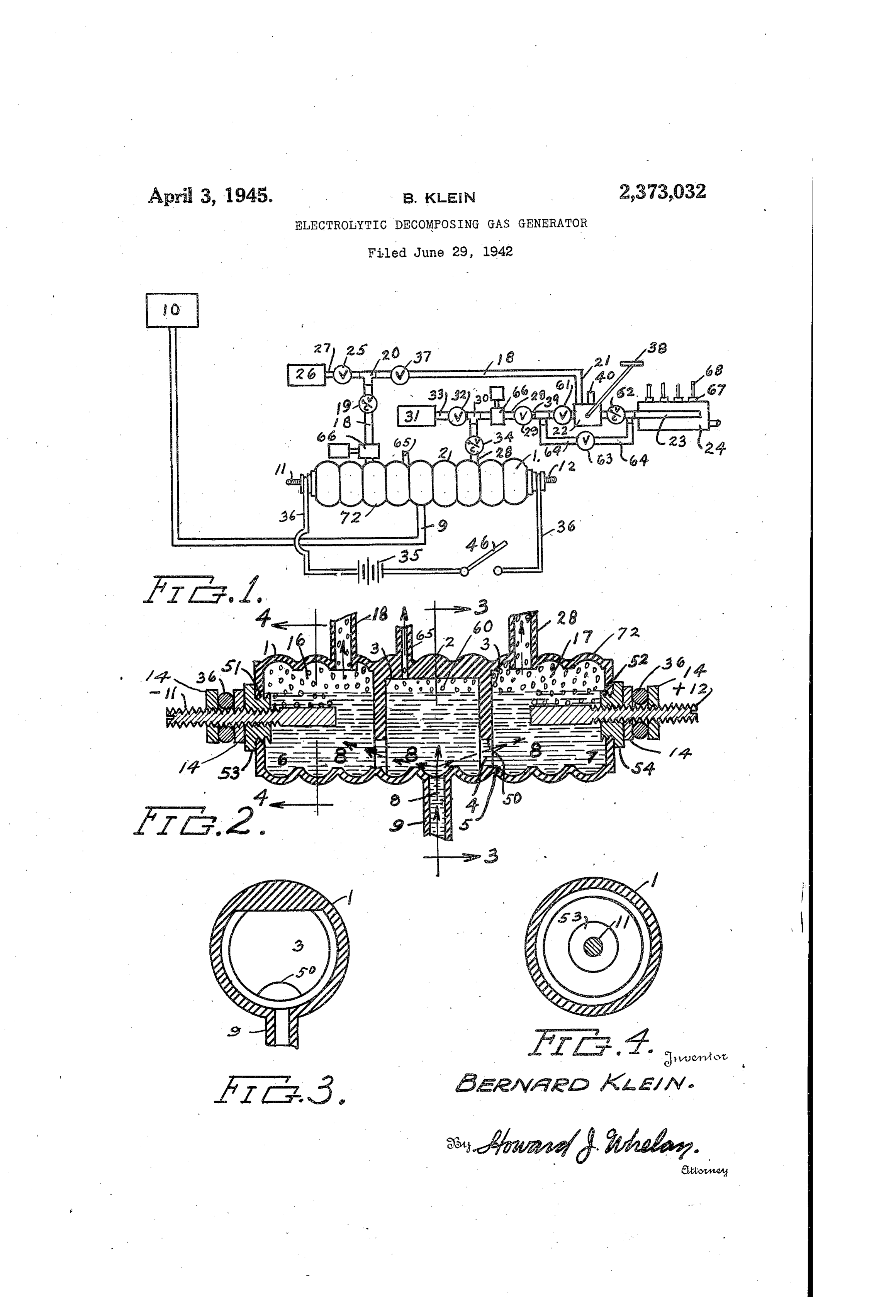
This invention refers to fuels for internal available to meet its needs. Under present con combustion engines and more particularly to a ditions the demand has increased and far ex method and device to be used in decomposing or ceeds the Supply. Any additional System of fuel extracting gases from liquids such as water and production that will be less costly and can use then arranging them for use as an explosive ingredients that can be found readily at hand mixture in engines of the internal combustion and not heretofore used for the purpose herein type. It has among its objects to provide a de described affords attractive possibilities. In this Vice that Will separate combustible gases from invention the fuel tank will be filled with water to the liquid compounds having same chemically which has been added an electrolyte, usually sul Combined in then, as for example: Oxygen and 10 phur trioxide or Sulphuric acid to increase its hydrogen from water, through an electrolytic conductivity so an electric current will pass process. Another object is to have the device through it. The fluid is then passed from the of such construction as, to be readily adaptable tank to the generating device by a pump, vacuum for insertion or connection among the parts of talk, gravity or Whatever System for the fuel a conventional internal combustion engine of 15 supply the vehicle may be equipped with. The the automobile, airplane, boat or other type device is preferably placed between the fuel tank Without requiring radical or complicated ar and engine and used with the existing carburetor, rangements for the purpose and capable of prac The device can be placed in the system conven tical employment. A further object is to pro iently, as it takes very little room, is of simple vide for the operation of the device in a conven 20 form, and has effective arrangement for attach ment to the system. An important feature of ient manner with adjustments permitting it to meet varied conditions encountered during op the device is in the fact that it has arrangements eration. A further object is to provide a device for augmenting the supply of gas generated by that will automatically supply treated water or the device. Another important feature of the other liquid medium as needed for the device. 25 device is that part of the gas generated may be A further object is to have the device adaptable used to l'eplenish its respective auxiliary tube. for adjustment by remote control or at a distant In the drawing which indicates a form of this location remote from the operator, or user. It invention:
is a particular object of the invention to con Figure is a diagrammatic view showing the struct a self contained unit that can be applied : various parts used to form a complete System embodying this invention, to an internal combustion engine; and take rela tively Small Space and be attached thereto in a Figure 2 is a longitudinal view taken through Compact and attractive manner. the generator,
Other objects will become apparent as the in Figure 3 is a sectional view taken along line vention is more fully set forth. 3-3 of Figure 2, and
There has been difficulty heretofore in em Figure 4 is a sectional view taken along line ploying the combustible gases of relatively inex 4-4 of Figure 2.
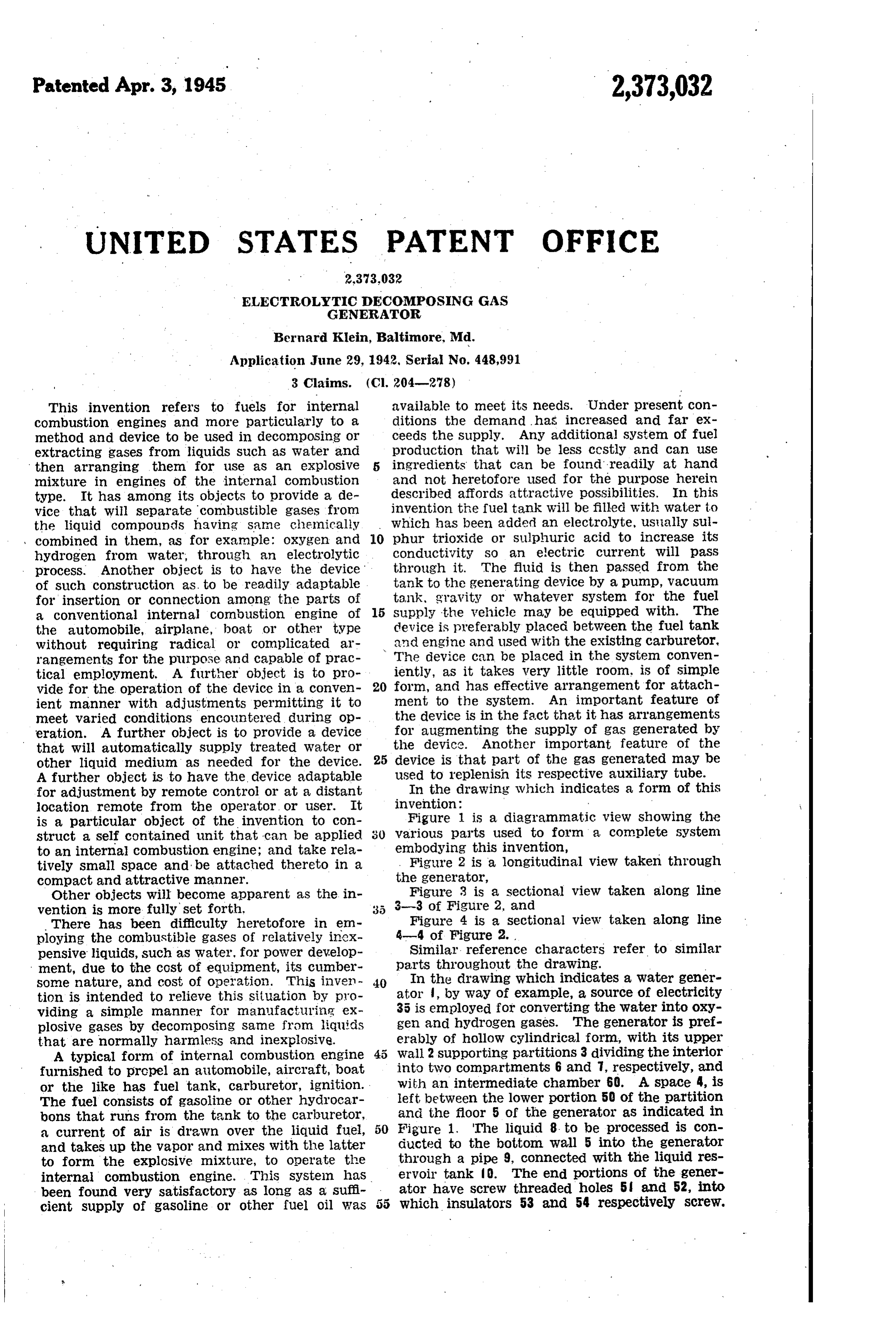
pensive liquids, such as water, for power develop Similar reference characters refer to similar ment, due to the cost of equipment, its cumber parts throughout the drawing. Some nature, and cost of operation. This inven 40 In the drawing which indicates a water gener tion is intended to relieve this situation by pro ator , by way of example, a source of electricity viding a simple manner for manufacturing ex 35 is employed for converting the water into oxy plosive gases by decomposing same from liquids gen and hydrogen gases. The generator is pref that are normally harmless and inexplosive. erably of hollow cylindrical form, with its upper A typical form of internal combustion engine Wall 2 supporting partitions 3 dividing the interior furnished to propel an automobile, aircraft, boat into two compartments 6 and 7, respectively, and or the like has fuel tank, carburetor, ignition. with an intermediate chamber 60. A space 4, is The fuel consists of gasoline or other hydrocar left between the lower portion 50 of the partition bons that runs from the tank to the carburetor, and the floor 5 of the generator as indicated in Figure 1. The liquid 8. to be processed is con a current of air is drawn over the liquid fuel, 50 ducted and takes up the vapor and mixes with the latter to the bottom Wall 5 into the generator to form the explosive mixture, to operate the through a pipe 9, connected with the liquid res internal Combustion engine. This system has ervoir tank O. The end portions of the gener been found very satisfactory as long as a suffi ator have screw threaded holes 5 and 52, into cient Supply of gasoline or other fuel oil was which insulators 53 and 54 respectively screw.
Page 3
The insulator 53, holds the negative cathode ter vent the liquid from sloshing back and forth. minal , and insulator 54, the positive anode In the operation of the device the tank 0, is terminal 2. The insulators and terminals are filled with water to which has been preferably water tight, and are constructed to serve as stuff added Sulphur trioxide or Sulphuric acid o in ling boxes. The terminals and 2 project into crease its conductivity. The tank is located high compartments 6 and 7 respectively, and contact enough so the liquid can run down into the gen the liquid residing therein. Electricity from a erator , by gravity, or supplied to the gas gen suitable source 35, feed the terminals when it erator by the fuel pump or other lifting method is desired to decompose the liquid, which in which then existS in the automobile or other this instance is Water, into its component gases () vehicle to which it is applied. The anode ter oxygen and hydrogen. The water is acidulated ninal f2 is connected to the positive side of an with Sulphur trioxide (SO3) or sulphuric acid electric battery or other electric source, and the (H2SO4) to improve its conductivity and electro cathode it is connected to the negative side of lytic decomposition. The current passing into the electric source. A Switch 46 completes the the water, when the circuit 36 is operating, electrical connections and may be placed on the causes hydrogen gas to liberate at the cathode instrument board convenient to the operator. terminal , and oxygen at the anode terminal 2. When the electric source is turned on by switch This is usually indicated by bubbles forming and 36, bubbles will form around the cathode and arising from the terminals. The hydrogen gas anode terminals and Will arise through the Solu collects in the compartment S and rises above 20 tion and be collected in their respective cham the water into the space 6 and flows out of the bers or spaces. The valve 37 is opened and pump outlet 8 into piping that conducts it to a cylin 66 started and allows gas to flow through pipes der when it is stored. Oxygen accumulating at 2 and check valve 9 into carburetor or other terminal 2 passes into compartment thence mixing device 22 which is opened or closed by through the liquid into the space fl. From 25 lever 38. Oxygen flows from the space 7, thence it passes into the piping 28. The piping through check valve 34, fitting 30, pipe 28, pump is provided with check valves 9 and 33, fittings 66, valve 29 and pipe 39 into the carburetor cr 20 and 39, carburetor 22, pipes 2 f, 23, 2, 33, 28 other mixing device 22 where the hydrogen is and 39, valves 25, 29 and 3 as indicated in the properly, mixed with air 40 or oxygen to give drawing. The internal combustion engine used proper combustion, after which the mixed gases for the operation is designated as 24. A by-pass are conveyed to the internal combustion engine connection with conventional accessories is in where they are ignited similarly to present day dicated to eliminate the carburetor as may be use of gasoline or fuel oil in internal combus required at any time. The hook-up comprises tion engines. An auxiliary cylinder 26 of hydro valves 63 and SE and check valve 62 and pipes 3. 5 gen is attached to pipe 27, valve 25 all of which 64. The circuit 36 when its switch 43 is closed, connect with fitting 20. An auxiliary cylinder causes electricity to fiow through the acidulated 3f, of oxygen is attached to pipe 33, valve 32 water from anode 2 to cathode ff. This breaks and fitting 39. The tanks 26 and 3 are used up molecules of water into hydrogen and oxy to supplement the supply of gases developed by gen. The hydrogen arises from the cathode , 40 the generator, or may be used when it is desired into the space S in chamber or compartment to remove the generator from the lines for re 6, and the oxygen from the anode terminal 2 pairs etc. The generator can be constructed into the compartment ; the partition 3, serving compactly and mounted close to the engine. to keep them apart and segregated. The space Lock nuts 4 provide for adjustment of elec 4 allows the Water to move freely from one com trodes and for attachment of electric wires partment of the generator to the other. The thereto.
current also can pass through the Water with The generator itself is preferably of insulating out obstruction by the partition. The partitions material such as any well known plastic, in order however mechanically prevent the hydrogen and to increase the efficiency of the generator and oxygen mixing with each other in the generator, 50 prevent conducting of electricity to the walls Any tendency of either hydrogen or oxygen to where the action would be slightly short circuit stray outside of their respective compartments ing.
is prevented by the intermediate chamber 60 The ribbed or corrugated bottom surface 5. which collects them. Such stray gases are ree Serves to Create an interruption in the movement movable through an outlet pipe 65, provided for 55 of the molecules or ions energized to a breaking the purpose. The vibration of the generator point by the electric current flowing from the under any use in the vehicle mentioned, will not electrodes 2 and respectively. The breaking be sufficient to mix the gases by reason of the point is that condition arising just prior to the partitions 3 and the intermediate chamber 6, separation of the water molecules (or other sub functioning as described. Pumps 66 or other 6) stances acted upon) into their atoms oxygen and conventional arrangement are utilized in the outs hydrogen. The effect of this curvilinear and let piping fB and 28, to force the hydrogen and obstructing construction seems to be that of a Oxygen respectively out of the compartments 6 mechanical disturbance or collision to the flow and 7 through piping 2 and 39 to the mixer of the ions, causing them to collide more easily or carburetor 22 on their way to the engine 24, 65 and induce separation of the atoms more quickly, to be ignited by Spark plugs 6 and ignition Sys than without it. This improves the effectiveness tem, 68. The hydrogen and oxygen are prefer of the generator and increases the eficiency. of ably combined through the medium of the spark the process. The walls of the tank are given and in doing so explode powerfully. The ex their corrugated form inside to reduce the slosh plosion causes the engine pistons to reciprocate 70 ing of the water in the lower portions, whilst the and operate the engine in the usual manner. upper Surfaces thereof serve to entrap the gases Low pressure explosions can be induced through and induce them to deposit their particles of loose a Stoichiometric mixture of hydrogen and Oxy Water thereon and cause the latter to drip back gen at a suitable ignition temperature. Ribs 2 into the main body of the water. This kaeps provide expanding mechanical space and pre 75 the escaping gases relatively dry. The partitions
Page 4
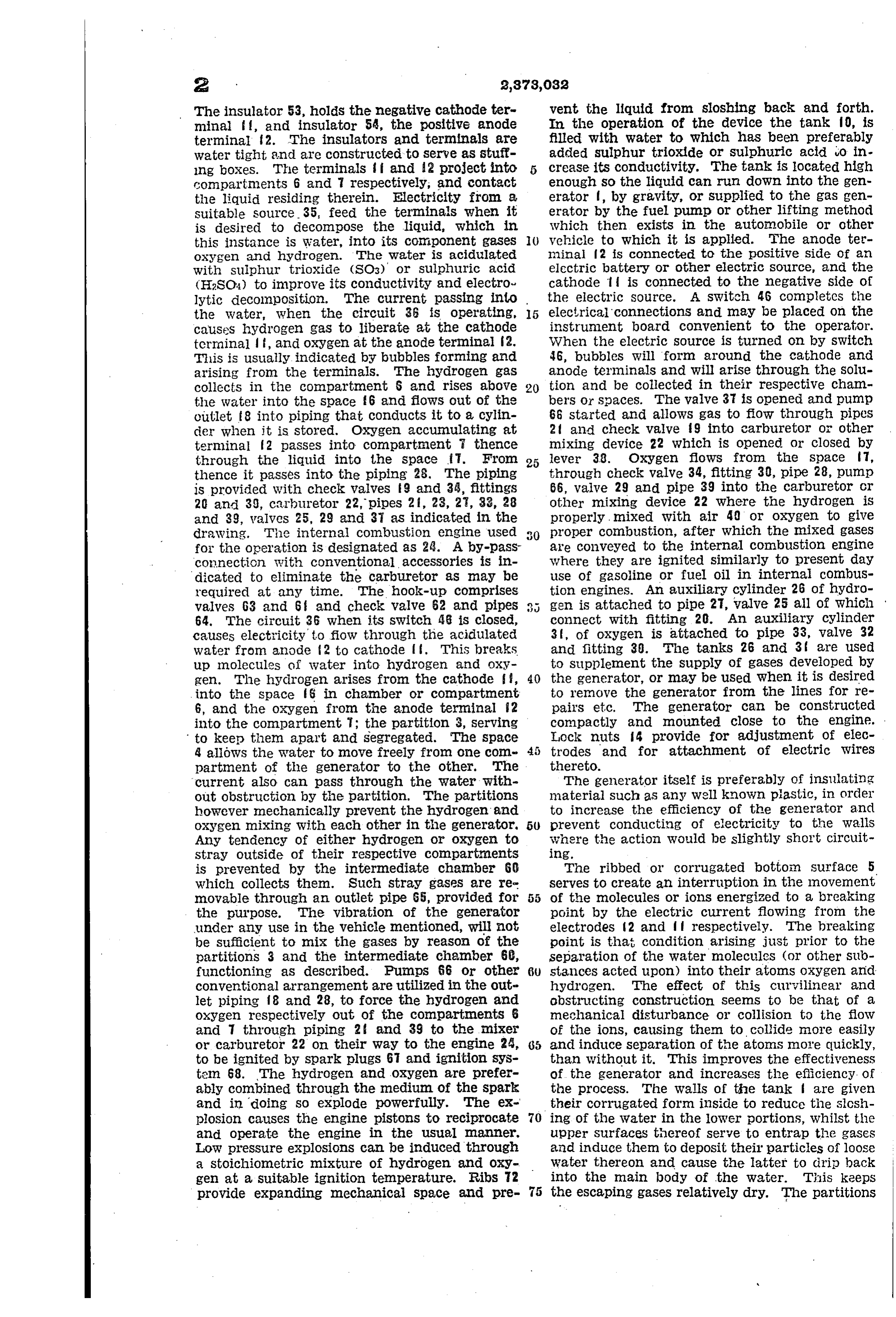
3 serve to cooperate with the corrugations in in the portion above the water and facilitate the preventing sloshing and reducing the escape of removal of moisture therefrom, partitions extend moisture from the chamber 60 to the chambers ing completely across the tank transversely with 6 and 7. This also diminishes any tendency passages therethrough for the circulation of of the incoming water to appreciably disturb the water therethrough but obstructing the gases level of the water in the electrode chambers. from passing above same, said partitions being The chamber 60 acts as a cushion device. arranged to divide the tank into compartments While but one form of the invention is indi for the hydrogen, oxygen and stray gases sepa cated in the drawing and described herein, it is rate from each other, and the conducting of not desired to limit this application to that par water
O to be processed thereto, electrodes in walls ticular form or in any other way, otherwise than of the compartments and separate from each other to facilitate the transmittal of the respec limited by the descriptions and claims, as it is tive gases to their respective compartments, and appreciated that other forms and constructions outlets from the chambers for removing the re could be embodied that would employ the same Spective gases therefrom.
principles and come within the Scope of the ap 3. A generator for facilitating the decomposi pended claims. tion and separation of hydrogen and oxygen re Having thus described the invention what is Sulting from the electrolysis of water, comprising claimed is: in combination, a tank having its longitudinal 1. A generator for automatic use and for de 24) dimension composing Water and segregating its component relatively long compared with its trans hydrogen and Oxygen, comprising in combination verse dimension, and having its internal Wall a hollow cylindrical generator relatively long Surface of corrugated form concentrically around horizontally for holding water, having a plurality same, water so as to dampen any sloshing movement of to be electrolyzed placed therein to a pre of Orifices therein said generator having an in determined level and to induce entrapment of ternally corrugated form adapted to accumulate the said gases derived from the electrolysis in gases therein and drain same above and prevent, the portion above the water and facilitate the sloshing of the water below, partition means in removal of moisture therefrom, partitions ex the interior of the generator extending through tending completely across the tank transversely portion of same and arranged to divide same into 30 with passages therethrough for the circulation compartments adapted to receive the hydrogen, of Water therethrough but obstructing the gases oxygen and stray gases segregatively from each from passing above same, said partitions being other, a plurality of electric terminals horizon arranged to divide the tank into compartments tally disposed and adjacent to the surface of the for the hydrogen, oxygen and stray gases sepa water projecting into the cylinder through some 35 rate from each other, and the conducting of water of said orifices, said terminals being arranged to to be processed thereto, electrodes in walls of the contact the water in said cylinder for electrolyz compartments and separate from each other to ing same when an electric current is passed from facilitate the transmittal of the respective gases the terminal through the water, and to direct the to their respective compartments, and outlets hydrogen to flow to its compartment, the oxygen 40 from the chambers for removing the respective to its compartment, and stray gases to their com Rases therefrom said compartment for the con partment. means for removing the hydrogen, ducting of water to the tank being arranged with oxygen and stray gases separately, for conveying its partitions to contain a space above the water same away for use.
2. A generator for facilitating the decom for the collection of air and other gases released therefrom independently separated from the position and separation of hydrogen and oxygen oxygen and hydrogen so as to be segregated there resulting from the electrolysis of water, compris from, an outlet in the last mentioned compart ing in combination, a tank having its longitu ment for the removal of said air and gases there dinal dimension relatively long compared with from, said electrodes being disposed within the its transverse dimension, and having its internal tank so as to be wholly covered by the water at wall surface of corrugated form concentrically the predetermined level, and the water being around Same, so as to dampen any sloshing move conducted to the tank adjacent the bottom there. ment of water placed therein at a predetermined of and connections for the electrodes for tieing level to be electrolyzed and to induce entrapment 55 it into a circuit.
of the said gases derived from the electrolysis BERNARD KLEIN.
Provenance
- Collection
- Cited prior art
- Original PDF
- patentimages.storage.googleapis.com →
- Filed
- 1942-06-29
- Pages
- 4
- Method
- pdftotext (the PDF's own text layer) + pdftoppm 300dpi page scans
- Source
- Google Patents bibliographic record
- Granted
- 1945-04-03
- Inventors
- Klein Bernard
- Transcribed from
- patentimages.storage.googleapis.com →