patent · US4261955
Vertical type porous membrane hydrogen generator
14 April 1981
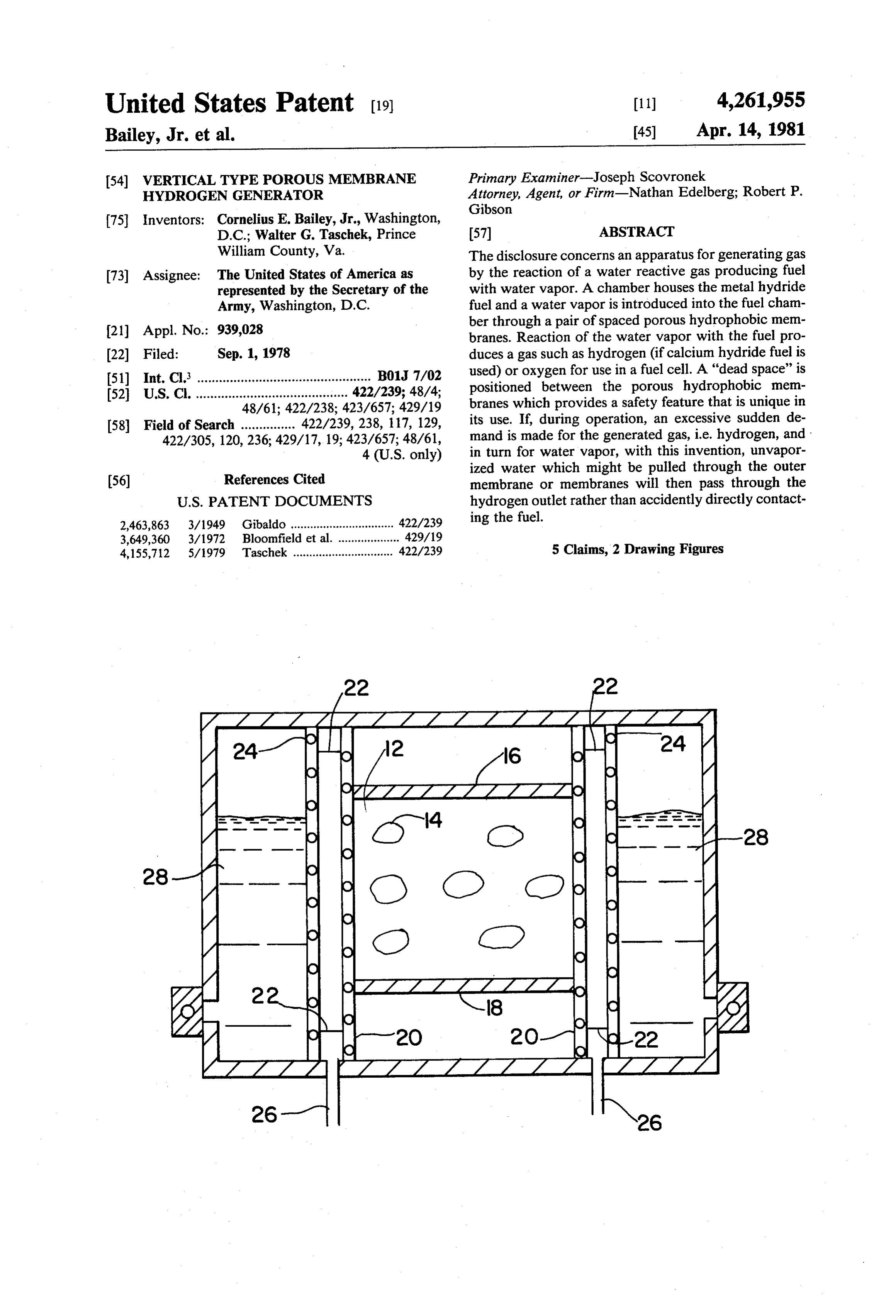
Page 1 — bibliographic record
United States Patent (19) 11 4,261,955 Bailey, Jr. et al. 45) Apr. 14, 1981
(54) VERTICALTYPE POROUS MEMBRANE Primary Examiner-Joseph Scovronek HYDROGEN GENERATOR Attorney, Agent, or Firm-Nathan Edelberg; Robert P. Gibson 75 Inventors: Cornelius E. Bailey, Jr., Washington,
D.C.; Walter G. Taschek, Prince 57 ABSTRACT
William County, Va. The disclosure concerns an apparatus for generating gas 73) Assignee: The United States of America as by the reaction of a water reactive gas producing fuel represented by the Secretary of the with water vapor. A chamber houses the metal hydride Army, Washington, D.C. fuel and a water vapor is introduced into the fuel cham ber through a pair of spaced porous hydrophobic mem (21) Appl. No.: 939,028 branes. Reaction of the water vapor with the fuel pro (22 Filed: Sep. 1, 1978 duces a gas such as hydrogen (if calcium hydride fuel is 51) Int. C. ................................................ B01J 7/02 used) or oxygen for use in a fuel cell. A "dead space' is 52 U.S. C. .......................................... 422/239; 48/4; positioned between the porous hydrophobic mem 48/61; 422/238; 423/657; 429/19 branes which provides a safety feature that is unique in 58) Field of Search ............... 422/239, 238, 117, 129, its use. If, during operation, an excessive sudden de 422/305, 120, 236; 429/17, 19; 423/657; 48/61, mand is made for the generated gas, i.e. hydrogen, and 4 (U.S. only) in turn for water vapor, with this invention, unvapor ized water which might be pulled through the outer (56) References Cited membrane or membranes will then pass through the
2,463,863 3/1949 Gibaldo ................................ 422/239 ing the fuel.
3,649,360 3/1972 Bloomfield et al. ................... 429/19 4,155,712 5/1979 Taschek ............................... 422/239 5 Claims, 2 Drawing Figures
24-72 A 24
-54 O 28
Page 2
Drawing sheet — no readable text.
Page 3
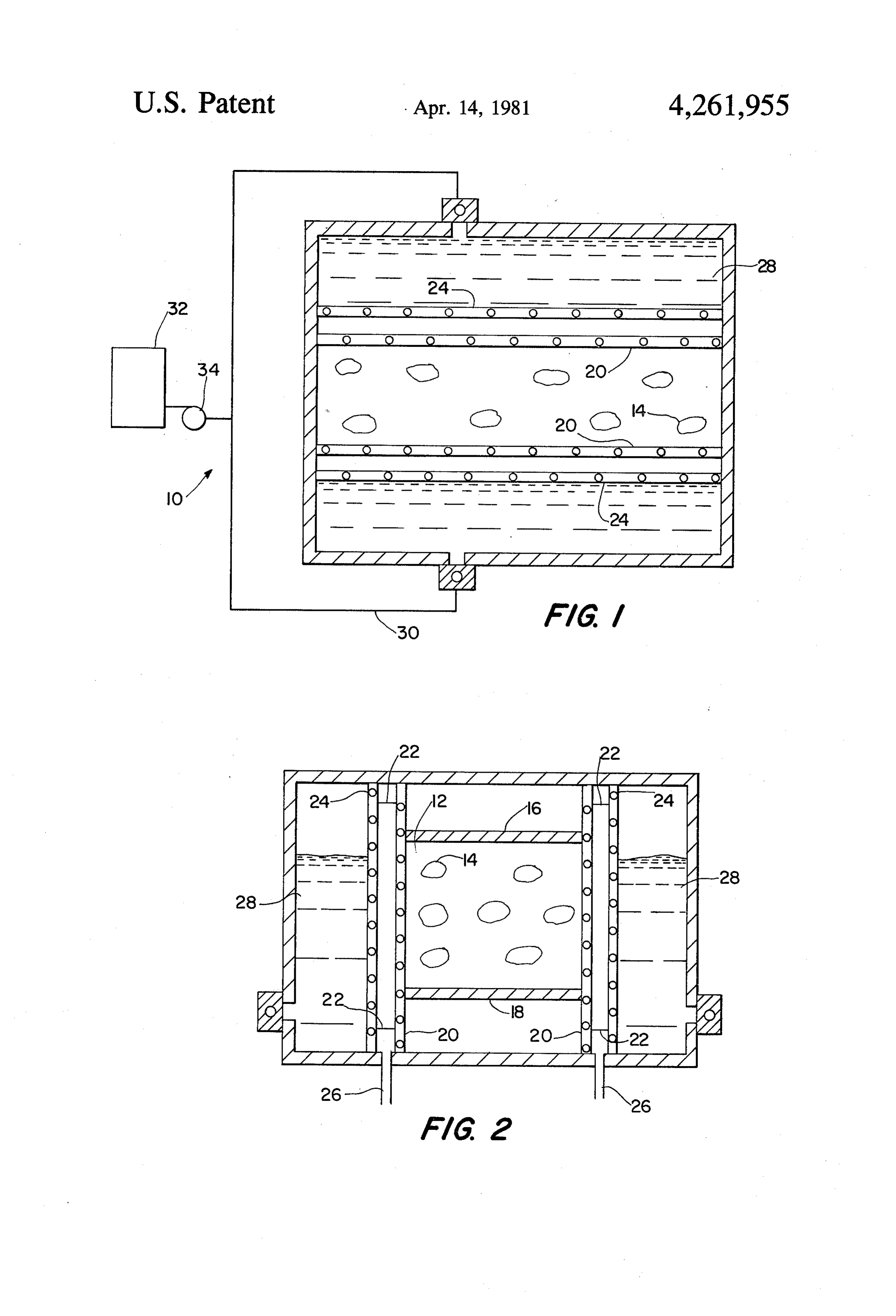
generator. These water chambers are connected by a
WERTICALTYPE POROUS MEMBRANE supply pipe 30 to a water reservoir 32 and a manifold 34 HYDROGEN GENERATOR is provided to balance the flow of water therebetween. In operation, when an electrical load is placed on the
DEDICATORY CLAUSE fuel cells (not shown), the fuel cell demands hydrogen The invention described herein may be manufac from the generators hydrogen outlet 26. This demand tured, used, and licensed by or for the Government for causes the level of water in the water chamber 28 to rise governmental purposes without the payment to us of thereby causing more water vapor to pass through any royalties thereon. membranes 24 and 20 into contact with the fuel 14 10 where hydrogen is produced. Produced hydrogen
BACKGROUND OF THE INVENTION flows out the outlets 26 as needed. If an abnormal sud This invention relates to the field of hydrogen gener den demand is made for hydrogen by the fuel cell, the atOS. sudden demand might cause unvaporized water to pass Among the problems in the use of demand responsive 15 through one or more of the outer membranes 24, with a hydrogen generators is that of a sudden requirement tendency to be drawn also through the inner membrane made on the water vapor such that water instead of the or membranes 20 except for the novel use of the spaced water vapor could be drawn into direct contact with membranes and intermediate outlets 26. Thus, unvapor the fuel, thus causing a malfunction. This is an improve ized water will be pulled through the hydrogen outlet ment over the gas generator disclosed in U.S. Pat. No. or outlets 26, rather than through membrane or mem 4,155,712, invented by one of the co-inventors of the 20 branes 20, and avoids directly contacting fuel. It is un present invention. derstood that other hydrogen-consuming devices other SUMMARY OF THE INVENTION than a fuel cell can be used in conjunction with this generator which could also place an abnormal hydro
The present invention has provided a solution to the 25 gen demand on the generator.
above stated problem by utilizing novel wall means for The porous membranes may be fabricated of any separating adjacently disposed solid fuel and water suitable material having hydrophobic characteristics. compartments. The novel wall means includes two One such material is a porous Teflon material. spaced apart porous hydrophobic membranes. During It is understood that while a specific embodiment has normal production of hydrogen gas, the membranes are of a character as to normally only pass water vapor 30 beenent to depicted for illustrative purposes, it will be appar those skilled in the art that various changes and from the water supply to the fuel compartment. How modifications can be made without departing from the ever, if an abnormal demand is made on the water va spirit and scope of the invention as set forth in the ap por, it could inadvertently cause unvaporized water to pass through one of the membranes. With the present pended claims.
invention, the demand in the hydrogen gas outlet, 35 We 1. A claim:
demand responsive gas generator for producing which outlet is positioned between the spaced-apart gas by chemical reaction of a solid fuel upon controlled membranes, would pull off the water before it could reach the metal hydride fuel. This is because the second exposure to a liquid vapor, said generator comprising: (1) a fuel compartment for storing solid fuel;
membrane forestalls water passage to the fuel. (b) a separate liquid compartment adjacently spaced This invention may be better understood from the 40 apart from said fuel compartment and having following detailed description taken in conjunction with the accompanying illustrative drawings. means to receive liquid water supplied thereto under a suitable pressure from an external reservoir
BRIEF DESCRIPTION OF THE DRAWING in a controlled manner;
FIG. 1 is a horizontal cross sectional view of the 45 (c) wall means between said fuel and water compart generator taken approximately on line 1-1 of FIG. 2, ments to maintain said compartments in spaced showing the connection to the water reservoir. apart relation;
FIG. 2 is a vertical cross sectional view of the genera (d) said wall means comprising at least one pair of tor taken approximately on line 2-2 of FIG. 1. spaced apart porous hydrophobic membranes 50 adapted to pass gaseous and vaporous mediums
DESCRIPTION OF THE PREFERRED while simultaneously adapted to restrict free pas EMBODIMENT sage of liquid water under normal demand opera As seen in the illustrative drawings, the generator E0 tion, said membranes designated as a first mem is depicted as a rectangular box and includes a suitable brane closest to and forming part of said liquid fuel compartment 12 for storing metal hydride fuel 14. 55 compartment, and a second membrane closest to The, as shown, compartment includes a cover 16 and a and forming part of said fuel compartment; floor 18 that extends the length of the generator. The (e) spacer means for maintaining said membranes in longitudinal side walls of the illustrative fuel compart spaced apart relation so as to form a gas passage ment are parallel and preferably comprised of the inner way therebetween; and most vertical porous hydrophobic membranes 20. Ref (f) outlet means connected with said gas passageway erence numeral 22 identifies suitable wall spacers hav for conducting produced gas away from the gener ing openings therein or otherwise constructed for per ator to an external gas utilization means, and for mitting gas passage. These spacers separate the inner also conducting away any excess liquid water col most membranes 20 from a similar second set of prefera lecting therein, bly parallel porous hydrophobic membranes 24 and 65 (g) whereby an abnormal demand for gas utilization provides a hydrogen gas passageway to outlets 26. As may cause a substantial sudden decrease in gas shown, a water chamber 28 is provided between the pressure in the gas passageway tending to cause outer membranes 24 and the outer side walls 11 of the liquid water to pass through said first membrane,
Page 4
and which liquid water is also directable away (b) said generator further includes suitable spacer from said generator through said outlet means be means for maintaining said membranes in spaced fore it can permeate the second membrane into said apart relation to form a gas passageway therebe fuel compartment. tween, said spacers being of a character so as to 2. The gas generator as defined in claim 1, wherein permit gas produced in said fuel compartment to said membranes are formed of porous Teflon sheet ma freely pass by said spacer means enroute to said gas terial. discharge outlet.
3. In a demand responsive hydrogen generator for 4. The gas generator as defined in claim 3, wherein said fuel compartment is bounded on two sides with said producing hydrogen gas by chemical reaction of a solid 10 water compartment means and with interposed wall fuel upon controlled exposure to a water vapor, means comprising said spaced apart hydrophobic mem wherein the generator includes a separate solid fuel branes to provide increased gas generation capabilities, compartment and liquid compartment means to receive said wall means being interposed between said fuel controlled amounts of liquid water, and further includes compartment and liquid water introducable into said a gas discharge outlet, wall means separating said fuel 15 water compartment means.
and liquid compartments, with the wall means having a 5. The gas generator as defined in claim 3, wherein hydrophobic porous membrane area adapted to pass periphery said fuel compartment is bounded on a major part of its gaseous and vaporous mediums while also restricting fuel compartment with said water compartment means and said being separated along said major part free passage of liquid water therethrough, the improve 20 of its periphery from ment wherein the aforesaid water compartment means by said wall means comprising said spaced apart (a) said wall means comprises a pair of spaced apart hydrophobic membranes.
hydrophobic membranes; and six
Provenance
- Collection
- Cited prior art
- Original PDF
- patentimages.storage.googleapis.com →
- Filed
- 1978-09-01
- Pages
- 4
- Method
- pdftotext (the PDF's own text layer) + pdftoppm 300dpi page scans
- Source
- Google Patents bibliographic record
- Granted
- 1981-04-14
- Inventors
- Cornelius E. Bailey, Jr.; Walter G. Taschek; United States Department of the Army
- Transcribed from
- patentimages.storage.googleapis.com →