patent · US6368492
Hydrogen generation by electrolysis of aqueous organic solutions
9 April 2002
Page 1 — bibliographic record
(12) United States Patent (10) Patent No.: US 6,368,492 B1 Narayanan et al. (45) Date of Patent: Apr. 9, 2002
(54) HYDROGEN GENERATION BY FOREIGN PATENT DOCUMENTS EASSIs OFAOUEOUS ORGANIC JP 59-209277 11/1984
(75) Inventors: Sekharipuram R. Narayanan, E. 'E' A. Altadena; William Chun, Los Angeles;
Barbara Jeffries-Nakamura, San OTHER PUBLICATIONS
Marino; Thomas I. Valdez, Covina, all of CA (US) Kosek et al., “A Direct Methanol Oxidation Fuel Cell',
(73) Assignee: California Institute of Technology, Hamnett et al., “Electrocatalysis and the Direct Methanol Pasadena, CA (US) Fuel Cell”, Chemistry & Industry, No. 13, 480–483 (Jul.
(*) Notice: Substylisher's Narayanan et al., “Implications of Fuel Crossover in Direct pU.S.C. 154(b) by 0 days. Methanol Fuel Cells”, Abstract No. 73, pp. 126-127 (1993) no month available.
Narayanan et al., “Studies on the Electro-Oxidation of (21) Appl. No.: 09/506,170 Methanol and Formaldehyde at Carbon-Supported Platinum
(22) Filled: Feb. 17,9 2000 and Platinum Alleyy Electrodes', pp
available.
Related U.S. Application Data Zawodzinski et al., “Methanol Cross-over in DMFC’s (62) Division ivision of application No.
of application No. 09/123.957, 95 f, filed on Jul.
illed on Jul. 28
Z8, Development of Strategies or Minimization”, Abstract 613, 1998, which is a continuation of application No. 08/926,947, pp. 960 (1992) no month available. filed on Sep. 10, 1997, now abandoned. sk cited - by examiner (51) Int. Cl." .................................................. C25B 1/02 (52) U.S. Cl. ........................................ 205/638; 205/637 Primary Examiner K. Mayekar (58) Field of Search .................................. 205/637,638 (74) Attorney, Agent, or Firm-Fish & Richardson, PC (56) References Cited (57) ABSTRACT
organic fuel. The electrolyte is a Solid-state polymer mem 3.013,098 A 12/1961 Hunger ........................ 136/86 brane with anode and cathode catalysts on both Surfaces for 3,143,440 A 8/1964 Hunger et al. ................ 136/89 electro-oxidization and electro-reduction. A low-cost and 4,341,608 A * 7/1982 St. John ........... ... 204/129 portable hydrogen generator can be made based on the 4,390,603 A 6/1983 Kawana et al. ............... 429/30 device with organic fuels Such as methanol.
5,599,638 A 2/1997 Surampudi et al. ........... 429/33 15 Claims, 4 Drawing Sheets
Carbon dioxide Out
circulating fuel Solution
reservoirigaS Separator
-hydrogen Out
Page 2
Drawing sheet — no readable text.
Page 3
Drawing sheet — no readable text.
Page 4
Drawing sheet — no readable text.
Page 5
Drawing sheet — no readable text.
Page 6
HYDROGEN GENERATION BY According to one embodiment of the invention, a pre ELECTROLYSIS OF AOUEOUS ORGANIC ferred organic solution is methanol, CHOH. The electroly SOLUTIONS sis of methanol to hydrogen and carbon dioxide can occur at a low operating Voltage of about 0.4 V. This may lead to a
This is a divisional of U.S. Ser. No. 09/123,957 filed Jul. 5 Significant reduction in energy consumption of more than 28, 1998 (pending), which is a continuation of U.S. Ser. No. 70% compared to electrolysis of water. The cost of hydrogen 08/926,947, filed Sep. 10, 1997 (abandoned). produced by using the present invention, including the cost
ORIGIN OF THE INVENTION
of the methanol, may be about 50% of the usual amount of hydrogen produced by the electrolysis of water.
The invention described herein was made in the perfor Another aspect of the invention is the construction of the mance of work under a NASA contract and is subject to the electrolytic cell. A preferred cell has an integrated provisions of Public Law 96-517(35 U.S.C. 202) in which membrane-electrode assembly which includes two catalyzed the Contractor has elected to retain title. electrodes each bonded to one side of a Solid proton conducting polymer membrane. The Solid polymer Serves as
FIELD OF THE INVENTION 15 the electrolyte. One advantage of the Solid membrane elec
The present invention relates to generation of hydrogen trolytic cell is elimination of the conventional liquid acidic by electrolysis of aqueous organic Solutions, and more or alkaline electrolyte which can cause various problems Specifically to an electrolysis System with a Solid electrolyte including corrosion of cell components, poor activity of membrane cell for producing hydrogen. catalysts, and parasitic shunt currents. The Solid membrane electrolytic cell can also be made robust and compact.
BACKGROUND OF THE INVENTION Yet another aspect of the invention is a power generation Hydrogen is known to have many applications ranging System having a hydrogen fuel cell and a hydrogen generator from Synthesis of chemicals. Such as ammonia, petroleum based on electrolysis of an organic fuel.
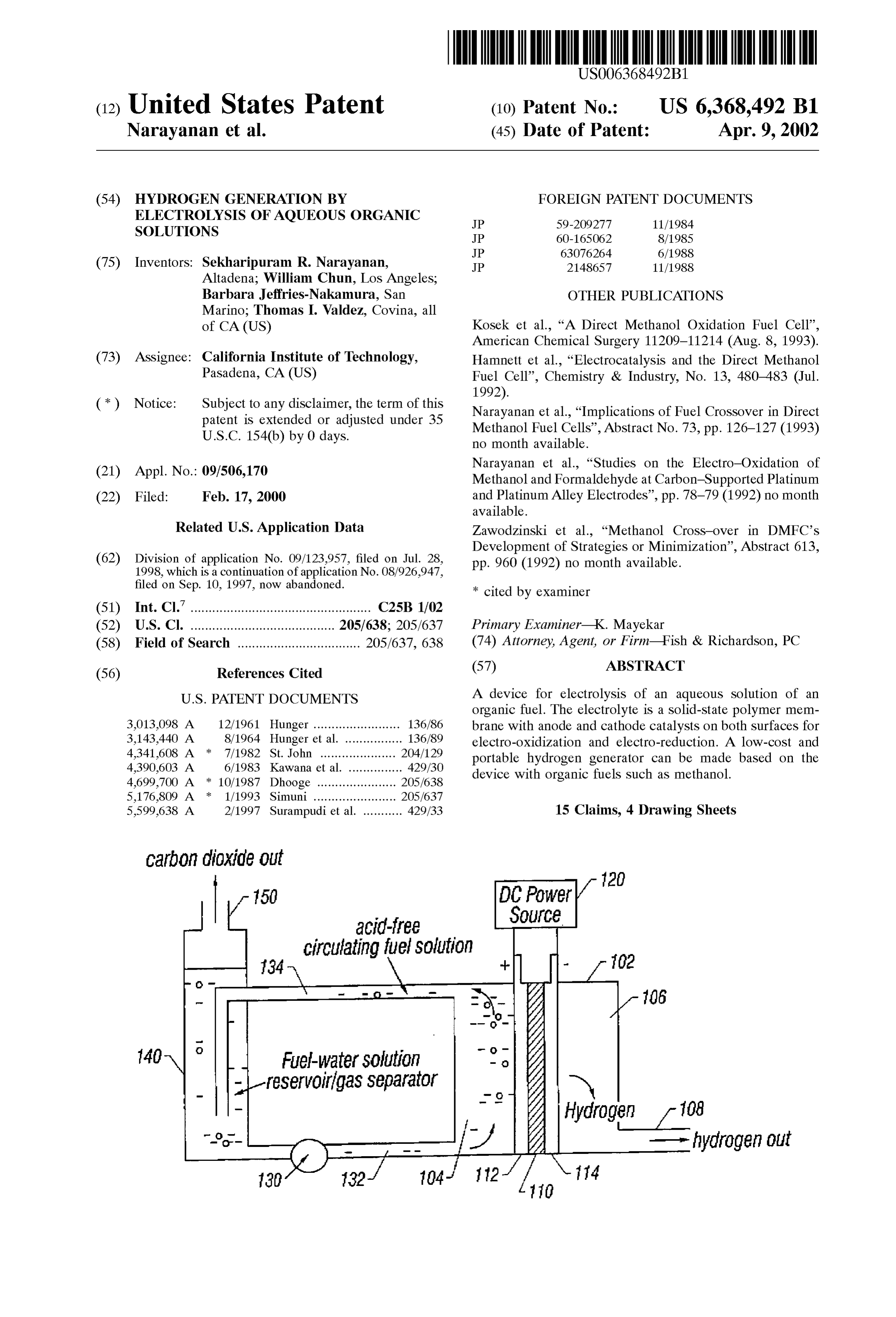
refining in producing high octane gasoline and aviation jet 25 BRIEF DESCRIPTION OF THE DRAWINGS fuel and in removal of Sulfur, hydrogenation in various industrial processes, to propellant fuels in combination with These and other features and advantages of the present oxygen or fluorine for rockets and Spacecraft. Pure hydrogen invention will become more apparent in light of the follow usually takes a form of a colorless, odorleSS, and tasteleSS ing detailed description, as illustrated in the accompanying gas composed of diatomic molecules, H2, under ordinary drawings, in which:
conditions. Alternatively, pure hydrogen may also be Stored FIG. 1 is a schematic illustration showing one embodi in the liquid phase under a certain preSSure. Pure hydrogen ment of an electrolysis cell having a Solid-state membrane is usually produced by producing the hydrogen gas. electrolyte.
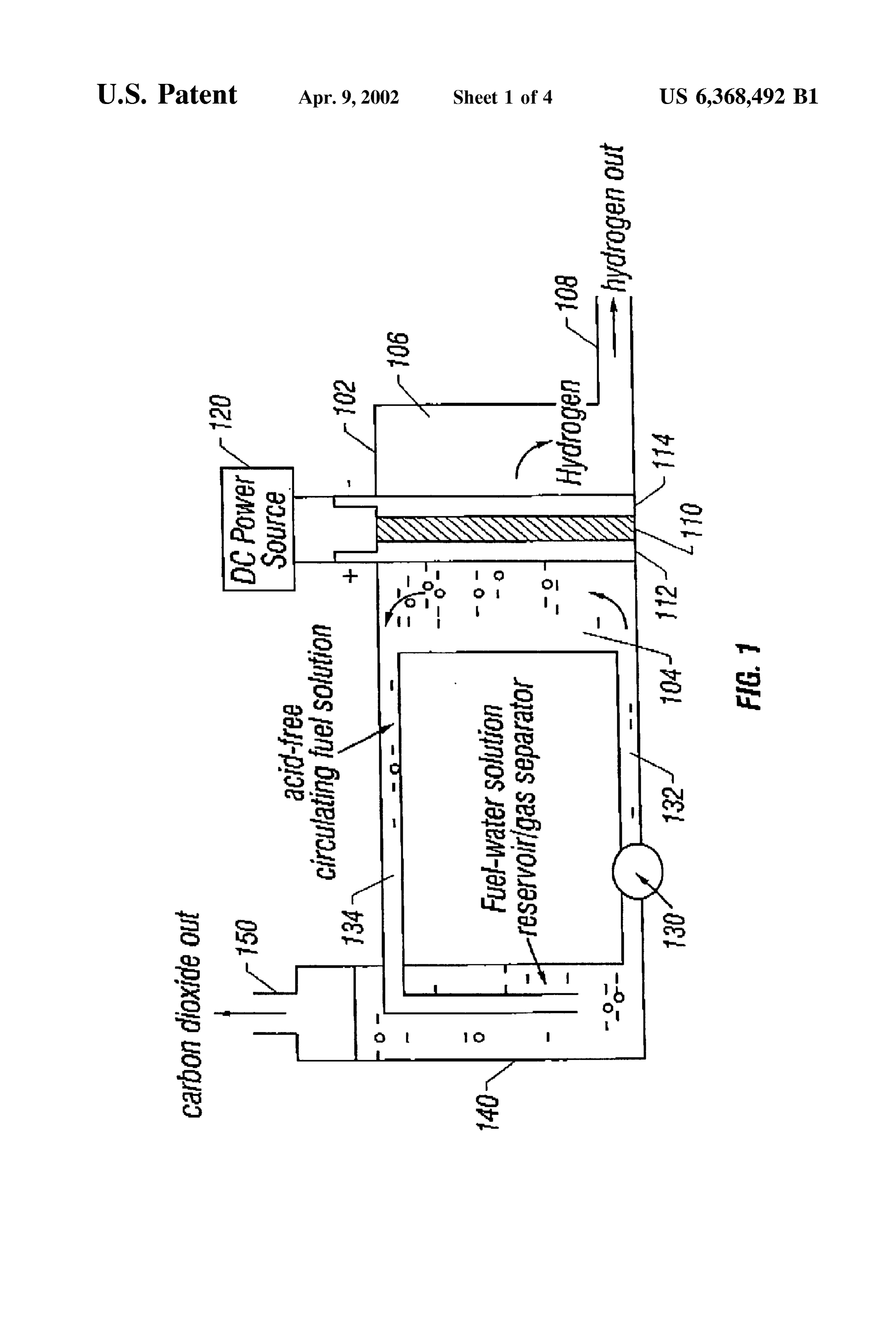
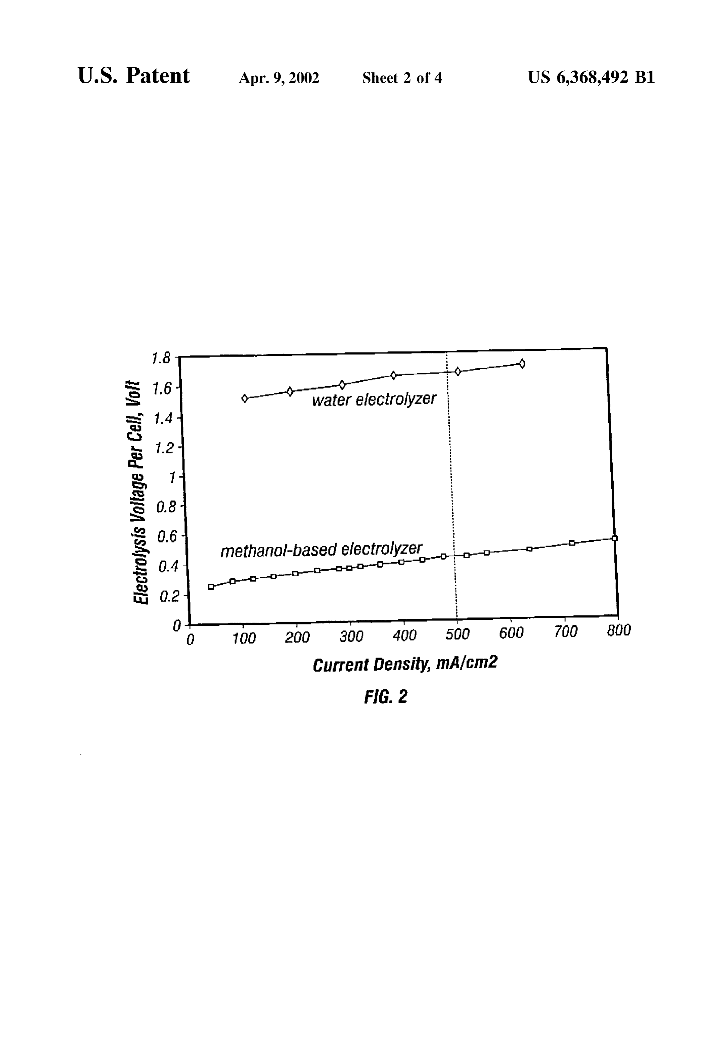
One conventional method of producing the hydrogen gas FIG. 2 is a chart of typical electrolysis Voltage per cell as is by electrolysis of water. This is a simple process in which 35 a function of current density for a Special hydrogen genera water (H2O) is decomposed into hydrogen (H) and oxygen tor in accordance with the preferred system of FIG. 1. (O) by electrochemical reactions at the electrodes in an FIG. 3 is a schematic illustration of a scheme for purifi electrolytic cell. The cost of hydrogen generation by elec cation of hydrogen.
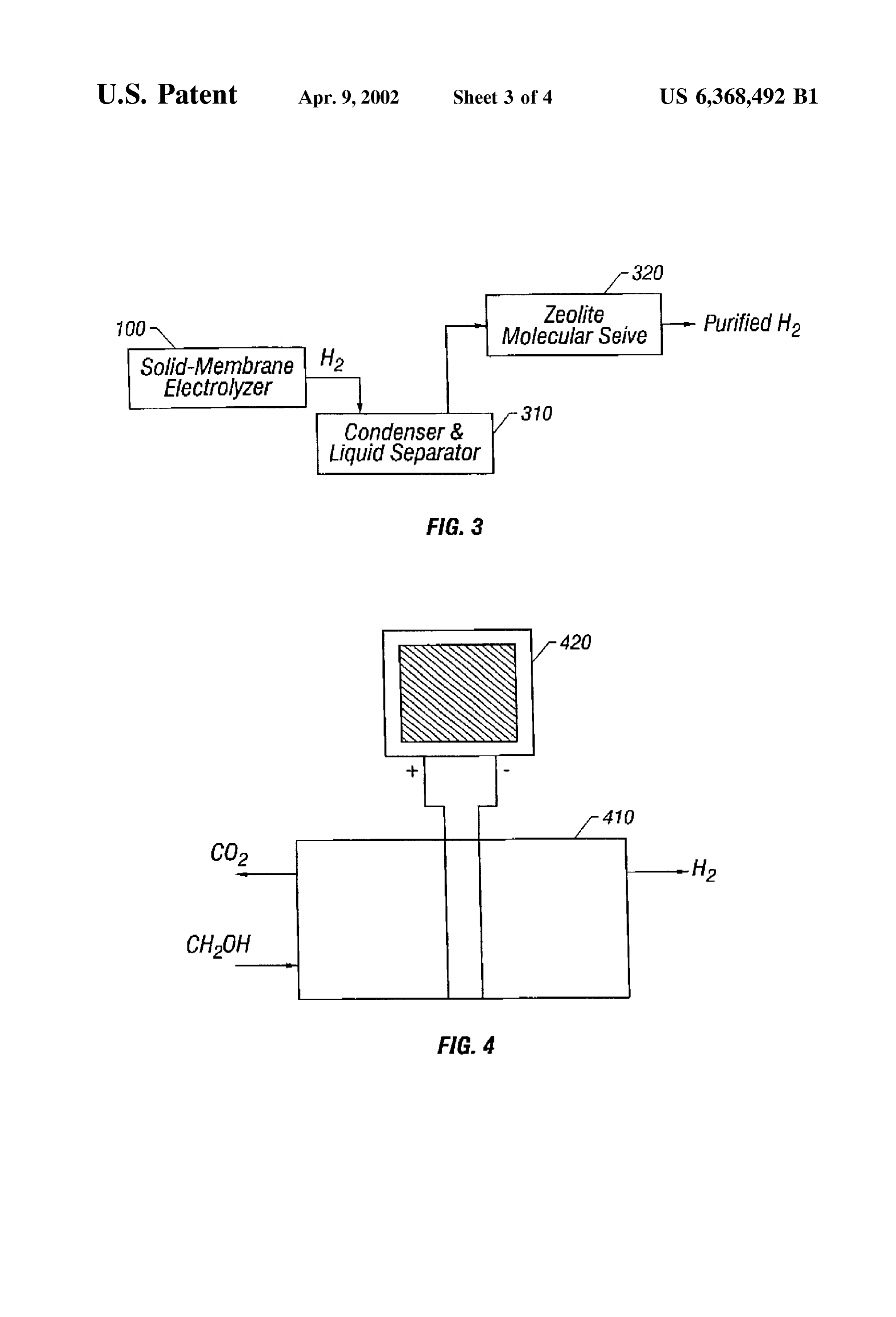
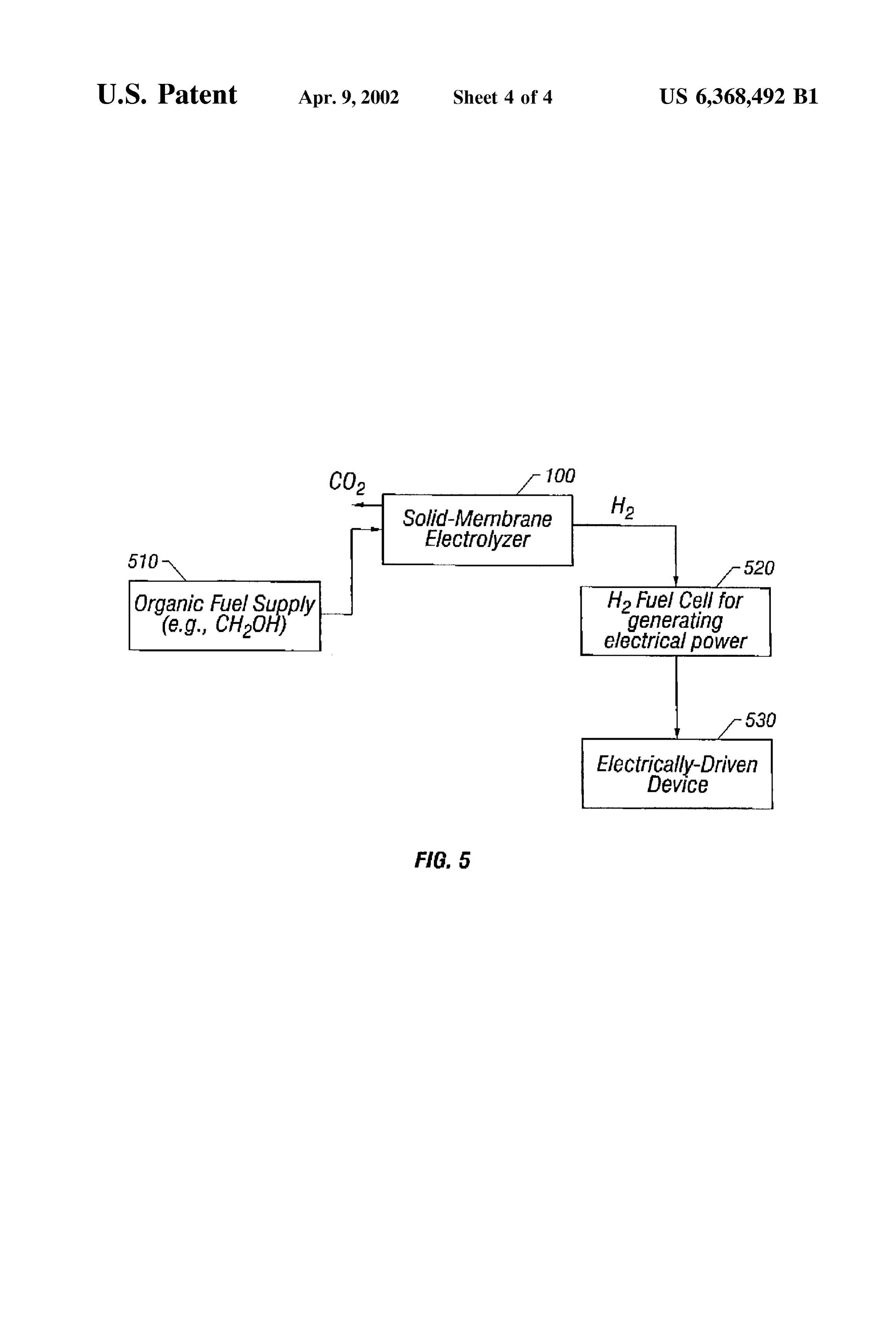
trolysis of water is mainly determined by the cost of energy consumption Since the cost of equipment diminishes over 40 FIG. 4 is a Schematic illustration showing another many production cycles. The energy consumption in an embodiment of an electrolysis cell having a Solid-State electrolysis process can be indicated by the operating Volt membrane electrolyte and a Solar array. age applied to the electrodes in the electrolytic cell. In FIG. 5 shows an electrical power generator based on a ordinary operating conditions, the higher the operating hydrogen fuel cell and a Solid-State membrane electrolysis Voltage, the larger the energy consumption. A typical oper 45 cell.
ating Voltage for electrolysis of water is approximately about DETAILED DESCRIPTION OF THE 1.4 Volt or higher. INVENTION Due to the Simplicity of electrolysis proceSS and the equipment, conventional water-based electrolysis Systems FIG. 1 shows a hydrogen generator 100 having a solid are widely used in portable or Stationary hydrogen genera 50 State membrane electrolyte according to the invention. An tors for Small and large Scale hydrogen generation. electrolytic cell 102 encloses an electrolyte membrane 110 Specifically, hydrogen generation devices can be used as which is operable to conduct protons and exchange cations. fuel Supply for fuel cells that generate electricity by con An anode 112 is formed on a first Surface of the membrane Suming hydrogen. 110 with a first catalyst for electro-oxidation and a cathode 55 114 is formed on a Second Surface thereof opposing the first
SUMMARY OF THE INVENTION Surface with a Second catalyst for electro-reduction. A DC The inventors recognized that it could be useful to pro electrical power supply 120 is connected to the anode 112 duce hydrogen based on devices using an alternative fuel. with its positive output terminal and cathode 114 with its The present disclosure describes an alternative electrolysis negative output terminal. A DC voltage is applied on the System for producing hydrogen. According to a first aspect 60 electrodes during operation So that a current Suppled by the of the invention, an aqueous organic Solution, rather than power supply 120 flows from the anode 112 towards the water, is used in an electrolytic cell for producing the cathode 114.
hydrogen gas. A preferred organic Solution is the type having The membrane 110 divides the electrolytic cell 102 into an operating Voltage lower than that of the water in an an anode chamber 104 on the side of the anode 112 and a electrolysis process. Use of this type of organic Solutions 65 cathode chamber 106 on the side of the cathode 114. The reduces the energy consumption and therefore the cost of the anode chamber 104 of the electrolytic cell 102 is connected generated hydrogen gas. to a feeding conduit 132 for feeding an organic Solution to
Page 7
the anode 112 from a reservoir and a circulation conduit 134 generator 100. Some aspects of the electrode-membrane for sending the organic solution from the anode chamber 104 assembly have been disclosed elsewhere by the inventors, to the reservoir 140. A fluid pump 130 can be deployed for example, U.S. Pat. No. 5,599,638, U.S. patent applica anywhere in the circulation path of the fluid, for example, in tion Ser. No. 08/569,452 filed on May 28, 1996 U.S. Pat. No. the feeding conduit 132 as shown in FIG.1. A gas outlet 150 5 5,773,162 and Ser. No. 08/827,319 filed on Mar. 26, 1997 is located in the reservoir 140 for releasing gas. U.S. Pat. No. 5,995,231, the disclosure of which is incor Alternatively, the gas outlet 150 may be located in the anode porated herein by reference. The brevity in describing vari chamber 104 of the electrolytic cell 102. ous parts of the present invention is Supplemented by the The cathode chamber 106 of the electrolytic cell 102 disclosure of the above references.
confines the hydrogen gas generated at the cathode 114. A In a preferred implementation, the membrane 110 is gas feed port 108 in the cathode chamber 106 is used to formed from NafionTM, a perfluorinated proton-exchange export the hydrogen gas. membrane material. NafionTM is a co-polymer of tetrafluo In operation, a mixture of an organic fuel (e.g., methanol) roethylene membrane and perfluorovinylether sulfonic acid. Other materials can also be used, for example, modified and water is fed into the anode chamber 104 of the electro lytic cell 102. Electrochemical reactions happen Simulta 15 perflourinated Sulfonic acid polymers, polyhydrocarbon Sul neously at both the anode 112 and cathode 114 by consum fonic acid, and composites of two or more kinds of proton ing the electrical energy Supplied by the power Supply 120. eXchange membranes. Different materials with carboxylic The electro-oxidation of the organic fuel at the anode 112 In acid groups may also be used for constructing membranes. produces hydrogen ions, H" (i.e. protons), that migrate to the addition, polystyrene Sulfonic acid (“PSSA’) and poly cathode 114 due to the difference in the electrical potentials (vinylidene fluoride) (“PVDF) may also be used. of the electrodes. At the cathode 114, the protons are further The maintenance of high proton conductivity of the reduced to hydrogen molecules (H2) by electro-reduction. membrane 110 is important to the efficiency of the hydrogen generator 100. The thickness of the proton-conducting solid
For example, when methanol is used as the fuel, the polymer electrolyte membranes may be in a range from electro-oxidation of methanol at the anode 112 can be 25 about 0.05 mm to about 0.5 mm. Membranes thinner than represented by about 0.05 mm may result in membrane electrode assem blies which are poor in mechanical Strength, while mem branes thicker than about 0.5 mm may Suffer damaging
The protons (H") generated at the anode 112 traverse dimensional changes induced by Swelling of the polymer by through the proton conducting membrane 110 to the cathode the liquid fuel and water Solutions and also exhibit excessive 114 and the electrons, also generated at the anode 112, are resistance. The ionic conductivity of the membranes should conducted through the electrical wires and the power Supply be greater than 1 ohm' cm to have a tolerable internal 120 to the cathode 114. The hydrogen ions and the electrons resistance.
are combined at the cathode 114 through electro-reduction A membrane may be formed with various methods. The of protons to generate the hydrogen gas: 35 following is an example of making a membrane with the Nafion 117 from DuPont. Nafion 117 is first cut to the proper size. Proper sizing is important, Since the end materials will be conditioned. First, the Nafion 117 is boiled in a hydrogen
Hence, the overall electrolytic reaction in the hydrogen 40 peroxide solution with a concentration about 5% for approximately 1 hour in a temperature ranging from about generator is: 80 C. to 90° C. This removes any oxidizable organic CHOH+HO+Electrical Energy-CO+3H. impurities. Following this peroxide boiling Step, the mem brane is boiled in de-ionized water, at about 100° C., for
The carbon dioxide gas (CO) produced at the anode 112 is approximately 30 minutes. Hydrogen peroxide adsorbed released through the gas outlet port 150 as a by-product and 45 into the membrane is removed along with other water the hydrogen gas is exported through the port 108. Soluble organic materials from the membrane. Various of organic fuels may be used. Preferably, organic Next, the above-processed membrane is boiled in a Sul fuels with low thermodynamic potential for electrolysis are furic acid Solution. A one-molar Solution of Sulfuric acid is used to achieve low operating Voltages. This reduces the prepared by diluting commercially available 18-molar con electricity expense in the hydrogen generation The inventors 50 centrated ACS-grade sulfuric acid. The ACS-grade sulfuric discovered that methanol has a low operating Voltage for acid preferably has metal impurities in an amount less than electrolysis. A theoretically estimated operating Voltage for 50 parts per million. The membrane is boiled in the 1-molar electrolyzing methanol in the system 100 is about 0.02 V. sulfuric acid at about 100° C. to more completely convert the However, the electrolysis of methanol occurs at about 0.3 V material into a proton conducting form. in a practical hydrogen generator based on the System 100. 55 The processed material is Subsequently boiled in deion This operating Voltage is considerably lower than what is ized water at about 90-100° C. for approximately thirty necessary for electrolyzing water, e.g., about 1.4 V in a minutes. The water is discarded, and this boiling Step may be conventional water-based System for hydrogen production. repeated three more times to purify the membrane. Other fuels may also be used in accordance with the After the above washings, the membrane should be sub invention, for example, dimethoxy me thane, 60 Stantially free of Sulfuric acid and in completely "protonic' dimethoxymethane, trimethoxymethane, and trioxane. form. The membrane is Stored in de-ionized water in a Sealed These materials are generally referred to herein as methanol container ready for further processing. compounds with a structure of (CH), OH. Formaldehyde The anode 112 can be formed from a catalyst, a proton and formic acid can also be used. conducting ionomer Such as Nafion Solution, and hydropho The electrode-membrane assembly (“MEA") formed by 65 bic additives Such as Teflon, and water. Typical catalyst the electrodes 112 and 114 and the polymer membrane 110 loading levels used are in the range of 0.5–4 mg/cm. Lower has a significant impact on the efficiency of the hydrogen loading of catalyst in the range of 0.1–1.0 mg/cm of the
Page 8
S 6 catalyst also allows attainment of useful performance levels. hydrogen atoms. The other bond is to a hydroxyl, OH, The catalyst can be a platinum-ruthenium alloy particles group. The platinum is believed to disasSociate methanol either as fine metal powders, i.e. "unsupported', or dispersed from its hydrogen bonds to form M=C-OH-3H, where on high Surface area carbon , i.e. “Supported”. The high M is the Pt or other metal site catalyst. The ruthenium Surface area carbon may be a material Such as Vulcan disassociates the hydrogen from the water molecule (HOH) XC-72A from Cabot Inc., USA. A carbon fibersheet backing to form Ru-OH. These surface species then reassemble as can be used to make electrical contact with the particles of CO+6H"+6e. The H (protons) are produced at the anode, the electrocatalyst. Carbon papers (e.g., Toray'M paper) or and croSS the anode to the cathode where they are reduced. carbon cloth can be used as the electrode backing sheet. A This is called a bifunctional catalyst. Supported alloy electrocatalyst on a Toray' paper backing Any material which has a similar function of disassoci is available from E-Tek, Inc., of Framingham, Mass. ating the methanol and water as described may be used in Alternatively, both unsupported and Supported electrocata place of the platinum. The inventors have investigated lysts may be prepared by chemical methods, combined with Several Such materials and found alternatives to platinum, TeflonTM binder and spread on Toray'TM paper backing to including but not limited to, palladium, tungsten, Rhodium, produce the anode. 15 Iron, Cobalt, and Nickel which are capable of dissociating Platinum-based alloys in which a second metal is either C-H bonds. Molybdenum (MoC)), niobium (NbO) and tin, iridium, osmium, or rhenium can be used instead of Zirconium (ZbO2) may also be capable of dissociating platinum-ruthenium. In general, the choice of the alloy H-OH as M-OH. A combination of these are therefore depends on the fuel to be used in the fuel cell. Platinum good catalysts. The catalyst for dissociating the H-O-H ruthenium is preferable for electro-oxidation of methanol. bonds preferably includes Ru, Ti, Os, Ir, Cr, and/or Mn. For platinum-ruthenium, the loading of the alloy particles in Ruthenium may be replaced either wholly or partly by a the electrocatalyst layer is preferably in the range of from ruthenium-like material. The inventors found that iridium about 0.5 to about 4.0 mg/cm°. Generally, lower loading of has many characteristics which are similar to ruthenium. An electrocatalyst in the range of 0.1 to 0.5 mg/cm also allows embodiment of this aspect, therefore, uses a combination of attainment of useful performance levels. However, more 25 platinum, ruthenium and iridium in the relative relationship efficient electro-oxidation can be realized at higher loading 50-25-25. This adds the salt HIrCl to the initial materials levels, rather than lower loading levels. described above, in appropriate amounts to make a 50-25-25 Various experiments carried out by the inventors have (Pt-Ru-Ir) combination. It has been found that this cata ascertained that one particular preferred catalyst material is lyst also operates quite well, using less ruthenium. platinum-ruthenium (“Pt-Ru”). Various formulations Alternatively, ruthenium can be replaced by tin to form a allowing combination of those two metals are possible. The platinum-tin catalyst.
inventors found that a bimetallic powder, having Separate Another material which has been found to have some platinum particles and Separate ruthenium particles pro advantages is materials containing titanium compounds. duced a better result than a platinum-ruthenium alloy. The Any titanium alkoxide or titanium butoxide, e.g. titanium preferred Pt-Ru material used according to the present 35 isopropoxide or TiCl-can also be added to the original invention has a high Surface area to facilitate contact mixture. This forms an eventual combination of platinum between the material and the fuels. Both platinum and ruthenium-TiO, also formed in a 50-25-25 (P-Ru ruthenium are used in the catalytic reaction, and the inven TiO) combination.
tors found that it was important that the platinum and Platinum-ruthenium-osmium can also be used. OSmium is ruthenium compounds be uniformly mixed and randomly 40 added to the mixture as a salt HOsCl which has also been Spaced throughout the material, i.e., the material should be found to produce advantageous properties. homogeneous. Pt and Ru can be incorporated in Zeolites and clays to Different metals may be combined to form a platinumru form zeolite-based Pt-Ru or Pt-Ru-Ir catalysts by thenium bimetallic powder which has distinct sites of dif exploiting the acid catalytic properties of these materials. ferent materials. However formed, the extent of combination 45 Also, Pt cation complexes (e.g., amine chlorides) and Similar between the particles is preferably kept at a minimal level So ruthenium complexes can be exchanged with Zeolite mate that the active catalyst powder has a homogeneous mixture rial (ZSM, mordenites, etc.) and they can be treated with of Submicron size platinum particles and ruthenium par hydrogen at elevated temperatures (200-300° C.) to produce ticles. activated Pt-Ru catalysts with large Surface area. These Additives may be added to the above catalyst powder to 50 will reduce cost of catalysts for Oxidation of methanol. improve the electrolysis efficiency, including titanium diox Other materials may also be used as a catalyst for Oxida ide (TiO), rhodium (Rh), iridium (Ir), and osmium (Os). tion of methanol. For example, a combination of Pt and Further processing of this anode catalyst by combining Zirconium oxide can be used as a catalyst. This may be with Nafion Solution, etc. results in an “ink'. The inventors prepared by an impregnation technique. The Zirconium have found the preferred ratio of platinum to ruthenium can 55 oxide is produced by a hydrolysis proceSS from Zirconium be between 60/40 and 40/60. The best performance is chloride or Zirconyl nitrate Solution. The platinum Salt Such believed to occur at 60% platinum, 40% ruthenium. Perfor as the chloride or nitrate is added to it in desired quantities mance degrades slightly as the catalyst becomes 100% and Sonicated until complete dissolution of the platinum Salt platinum. It degrades more sharply as the catalyst becomes occur and the platinum is uniformly distributed. A reducing 100% ruthenium. 60 agent Such as formaldehyde and Sodium formate is then The inventors believe that platinum-ruthenium catalyzes added and the solution thereof is heated. Pt will deposit on the electro-oxidation of methanol by aiding in disasSociating the Zirconium oxide.
the materials on the catalyst Surface. The material draws the The cathode 114 can be formed from a cathode catalyst, electrons out, and allows them to disasSociate. The reaction a proton-conducting ionomer Such as Nafion Solution, and can be explained as follows. 65 hydrophobic additives such as Teflon and water. The cathode Methanol is a carbon compound. The carbon atom is 114 can be a gas diffusion electrode in which platinum or bound to four other atoms. Three of the bonds ate to palladium particles are bonded to the Second Surface of the
Page 9
membrane 110. The cathode 114 can use both unsupported The press is then actuated to produce a pressure between and Supported platinum/palladium. Unsupported platinum/ 500 and 1500 psi, with 1250 psi being a preferred pressure. palladium black available from Johnson Matthey Inc., USA The pressure is maintained for about 10 minutes. Next, or Supported platinum/palladium materials available from heating is commenced by slowly increasing the temperature E-Tek Inc., USA are Suitable for the cathode. As with the to a range of 140-150° C. and preferably about 146 C. The anode, the cathode metal particles are preferably mounted on Slow process of increasing the temperature should take place a carbon backing material. The loading of the electrocatalyst over 25-30 minutes, with the last 5 minutes of heating being particles onto the carbon backing is preferably in a range of a time of temperature Stabilization. The temperature is about 0.5–4.0 mg/cm. Although higher loadings may allowed to stay at about 146 C. for approximately 1 minute. increase the oxidation, lower loading of catalyst in a range At that time, the heat is Switched off, but the pressure is of 0.1–1.0 mg/cm may also be used to achieve useful maintained.
performance levels. The press is then rapidly cooled using circulating water, One way to construct the cathode 114 is by first preparing while the pressure is maintained at about 1250 psi. When the a cathode catalyst ink. The cathode catalyst ink is preferably temperature reaches 45 C., approximately 15 minutes later, pure platinum or palladium, although other inkScan be used 15 the preSSure is released. The bonded membrane and elec and other materials can be mixed into the ink. For example, trodes are then removed and Stored in de-ionized water. 250 mg of platinum catalyst is mixed with 0.5 gram of water During operation of the cell, a fuel and water mixture including 37% mg of Teflon. The mix is Sonicated for five (containing no acidic or alkaline electrolyte) in the concen minutes and combined with a 5% solution of Nafion. The tration range of 0.5-3.0 mole/liter is circulated past anode mix is again Sonicated for five minutes to is obtain a uniform 112 in the anode chamber 102. Preferably, flow rates in the dispersal. This forms enough material to cover one piece of range of 10-500 ml/min. are used.
2x2" carbon paper. Unprocessed Toray carbon paper can be In addition to undergoing electro-oxidation at the anode, used without being teflonized. However, preferably the a portion of the liquid fuel dissolved in water can permeate material is teflonized as discussed above. The procedures are through solid polymer electrolyte membrane 110 without followed to make a 5% Teflon impregnated paper. The paper 25 electro-oxidation. This phenomenon is termed "fuel croSS is then heated at about 300° C. for one hour to sinter the over”. Fuel crossover results in consumption of fuel without Teflon particles. Catalyst ink is then applied to the paper as producing the hydrogen gas. It is therefore desirable to described above to cover the material with 4 mg/cm /g of Pt. minimize the rate of fuel croSSOver. Teflon content of the paper can vary from 3-20%, 5% being The rate of croSSover is proportional to the permeability the preferred. of the fuel through the solid electrolyte membrane and An alternative technique of forming the cathode 114 is by increases with increasing concentration and temperature. By a Sputtering process to form a Sputtered platinum electrode. choosing a Sold electrolyte membrane with low water This Sputtered platinum electrode has been found to have content, the permeability of the membrane to the liquid fuel Significant advantages when used as a plain air electrode. can be reduced. Reduced permeability for the fuel results in The inventors further contemplate that a decal layer 35 a lower croSSOver rate. Also, fuels having a large-molecular having a layer of catalyst on a Substrate (e.g., Teflon) can be size have a smaller diffusion coefficient than fuels which used for forming a catalyst layer onto a proton conducting have Small molecular size. Hence, permeability can be membrane. The catalyst layer is first formed on the substrate reduced by choosing a fuel having a large molecular size. from a pre-formed catalyst ink and Subsequently trans While water Soluble fuels are desirable, fuels with mod formed onto a membrane. This is described in detail in the 40 erate solubility exhibit lowered permeability. Fuels with above-incorporated U.S. patent application Ser. No. 08/827, high boiling points do not vaporize under normal operating 319 filed on Mar. 26, 1997. Decal transfer can be used for temperatures and their transport through the membrane is in forming both the anode and cathode of an electrolytic cell. the liquid phase. Since the permeability for vapors is higher Referring to FIG. 1, the membrane-electrode assembly than liquids, fuels with high boiling points generally have a (“MEA") can be formed by assembling the anode 112, the 45 low croSSOver rate.
membrane 110, and the cathode 114 together through a hot The concentration of the liquid fuel can also be lowered pressing process. to reduce the crossover rate. With an optimum distribution The electrodes and the membrane are first laid or stacked of hydrophobic and hydrophilic Sites, the anode Structure is on a CP-grade 5 Mil, titanium foil (e.g., 12-inch by 12-inch). adequately wetted by the liquid fuel to Sustain electrochemi The titanium foil prevents any acid content from the mem 50 cal reaction and excessive amounts of fuel are prevented brane 110 from leaching into the foil. from having access to the membrane electrolyte. Thus, an First, the anode electrode 112 is laid on the foil. The appropriate choice of anode Structures can result in the high proton conducting membrane 110 has been stored wet to performance and desired low croSSOver rates. maintain its desired membrane properties. The membrane AS noted above, the membrane should have a low per 110 is first mopped dry to remove the macro-sized particles 55 meability to the liquid fuel. Although a NafionTM membrane and then laid directly on the anode 112. The cathode 114 is has been found to be effective as a proton-conducting Solid next laid on top of the membrane 114. Another titanium foil polymer electrolyte membrane, per fluorinated Sulfonic acid is placed over the cathode 114. The edges of the two titanium polymer membranes such as AciplexTM (manufactured by foils are clipped together to hold the layers of materials in Asahi Glass Co., Japan) and polymer membranes made by position. The titanium foil and the membrane between which 60 Dow Chemical Co., Japan) and polymer membranes made the assembly is to be pressed includes two stainless Steel by Dow Chemical Co., USA, such as XUS13204.10 which plates which may be each approximately 0.25 inches thick. are similar to properties to NafionTM are also applicable. The membrane and the electrode in the clipped titanium Membranes of polyethylene and polypropylene Sulfonic foil assembly is carefully placed between the two stainless acid, polystyrene Sulfonic acid and other polyhydrocarbon Steel platens. The two platens are held between jaws of a 65 based Sulfonic acids (Such as membranes made by RAI preSS Such as an arbor preSS or the like. The preSS should be Corporation, USA) can also be used depending on the maintained cold, e.g. at the room temperature. temperature and duration of fuel cell operation. Composite
Page 10
membranes consisting of two or more types of proton of the driving current. FIG. 2 shows the measured current conducting cation-exchange polymers with differing acid voltage profile 210 for the methanol-based electrolytic cell equivalent weights, or varied chemical composition (such as in the Special System. Measurements from a commercial modified acid group or polymer backbone), or varying water water electrolyzer are also included as a curve 220 for contents, or differing types and extent of cross-linking (Such comparison. Current densities as high as 800 mA/cm can be as croSS linked by multivalent cations e.g., A1 3+, Mg 2+ attained at about 0.5 V. This is approximately one-third of etc.) can be used to achieve low fuel permeability. Such the Voltage at which water electrolyZerS operate under composite membranes can be fabricated to achieve high similar conditions. The high efficiency obtained in the ionic conductivity, low permeability for the liquid fuel and Special methanol-based System is in part due to the use of good electrochemical Stability. methanol and in part due to the membrane-electrode assem According to the invention, the permeability of the mem bly in accordance with the invention.
brane can also be changed by processing the Surface with Referring back to FIG. 1, the cathode chamber 106 may Zeolites. The Zeolite Structure with the appropriate pore size have methanol and water that traverses through the can be used to reduce the crossover of the fuel (e.g., membrane-electrode assembly from the anode chamber 104. methanol). Typically, zeolites such as Mol-siv 3A, 4A, 5A 15 Although the impermeability of the membrane-electrode from Union Carbide in the protonic form would be candidate assembly can be improved according to the invention, materials. These protonic forms can be produced by Standard complete impermeability is difficult to achieve with the methods of Ammonium ion exchange followed by calcining currently available polymer materials for membranes. The at about 550° C. in air. Such a calcined Zeolite can be used methanol and water permeate through the membrane into the in a number of ways, including: cathode chamber 106 mix with the generated hydrogen gas. a) mixed with the catalyst to fill the voids between the Therefore, the hydrogen gas from the cathode chamber 106 catalyst particles. usually needs to be purified by removing water and metha b) applied along with Nafion as a Second layer on the nol contents.
electrode. FIG. 3 shows a purification System that can be incorpo c) Combined with conductive carbon Such as Shawanigan 25 rated into the system 100 of the invention. The hydrogen gas black or graphite and mixed in with Nafion ionomer to produced from the hydrogen generator 100 is guided to a form a layer adjacent to the membrane electrolyte. vapor condenser/liquid separator 310 to remove the water The Zeolite containing layer may be formed to increase and methanol. A selective molecular seive 320 is located the concentration/content of Zeolite in the Subsequent layers. down stream to further remove traces of methanol. The This way, the catalyst utilization can be maintained without molecular seive 320 may have Molsiv 3X in the passage of restricting the access to methanol to the catalyst. When the the hydrogen gas, which allows only hydrogen to pass methanol attempts to enter the membrane, the Zeolite par through and traps the methanol.
ticles will SuppreSS Such a transport. Zeolite as a “crossover The electrolysis cell of the invention can be coupled to a inhibitor” is preferable to inert materials such as Teflon Solar cell or array to harneSS Solar energy. By coupling because Zeolites in the protonic form offer Some ionic 35 hydrogen generation to Solar cell-based electricity conductivity. This approach can be integrated with the generators, high efficiency Solar-powered hydrogen gas gen aforementioned Zeolite Supported metal catalysts. A mixture eration Systems can be constructed which would operate of Zeolite catalyst and Zeolite croSSOver inhibitor may be with Significantly lower energy requirements than State-of applied. the-art water electrolyzers being used today. Such a Solar AS can be appreciated from the foregoing description, the 40 powered hydrogen generator may be possible in part due to hydrogen generator 100 of FIG. 1 uses the proton the high efficiency of the electrolysis of the electrolytic cell conducting Solid polymer membrane 110 as electrolyte of the invention.
without the need for a free soluble acid or base electrolyte. FIG. 4 shows one embodiment of this aspect of the Thus, the only electrolyte is the proton-conducting Solid invention. A Solar array 420 with solar cells receives sunlight polymer membrane 110. No acid is present in free form in 45 and generates DC electrical power to drive the electrolytic the liquid fuel and water mixture. This avoids acid-induced cell 410.
corrosion of cell components. Multiple cell stacks of the device can be built using the Such cell construction offers considerable flexibility in the conventional designs for the bipolar water electrolyzers. choice of materials for the electrolytic cell 102 and the The present invention can be used in a portable or asSociated Sub-Systems. Furthermore, unlike cells which 50 Stationary mode for Small and large-scale hydrogen genera contain potassium hydroxide as liquid electrolyte, cell per tion. The present market in this area is dominated by formance does not degrade because Soluble carbonates are water-based electrolysis System. The on-site hydrogen gen not formed. A Solid electrolyte membrane also minimizes erators can be used in metallurgical processes for annealing, parasitic shunt currents. reduction, alloy processing and So on. The Small on-site The inventors built a special hydrogen generator based on 55 hydrogen Sources for gas chromatograph and flame ioniza the preferred configuration 100 using a methanol-water tion detectors in analytical laboratories is a significant niche Solution. The methanol concentration in the aqueous Solu market.
tions can be in a range of about 0.1 M to about 8 M. The The automotive market can also use hydrogen in heavy Special hydrogen generator has a Nafion" membrane Suit tanks with Several hazards of preSSurized hydrogen. The able for operation in a temperature range of about 5-120° C. 60 hydrogen produced in Such electrolytic generators has mini A platinum-ruthenium catalyst is used on the anode So that mized carbon monoxide and can be used as the fuel for the only by-product of electro-oxidation of methanol is hydrogen/oxygen fuel cells for producing electrical energy. carbon dioxide. The cathode has a platinum catalyst. The FIG. 5 shows a power generation System using a hydrogen catalyst loadings for both electrodes may be about 1-4 generator 100 and a hydrogen fuel cell 520. The hydrogen mg/cm. 65 generator 100 Supplies hydrogen as a fuel to the hydrogen One way to evaluate the efficiency of electrolysis is the fuel cell 520. The hydrogen fuel cell 520 is known in the art electrolysis Voltage of a single electrolytic cell as a function which consumes hydrogen to generate electricity. The elec
Page 11
trical power from the fuel cell 520 can be used to power an 5. A method according to claim 1, wherein Said anode electrically driven device 530. The entire system may be comprises a catalyst capable of inducing electro-oxidation of made as a mobile system which carries a fuel tank 510 to Said methanol.
Store a proper organic fuel Such as methanol. The hydrogen 6. A method according to claim 5, wherein Said catalyst generator 100 may be powered either by a battery or a solar comprises platinum.
cell. One application of Such a System is electric Vehicles 7. A method according to claim 6, wherein Said catalyst based on hydrogen fuel cells wherein the electrically-driven device includes the engine and other electrical devices on further comprises ruthenium.
the vehicles. 8. A method according to claim 7, wherein Said catalyst Although the present invention has been described in further comprises an element Selected from the group con detail with reference to a few preferred embodiments, one Sisting of titanium, rhodium, iridium, OSmium, and combi ordinarily skilled in the art to which this invention pertains nations thereof.
will appreciate that various modifications and enhancements 9. A method according to claim 6, wherein Said catalyst may be made without departing from the Scope and Spirit of further comprises an element Selected from the group con the present invention, which are further defined by the 15 Sisting of tin, iridium, OSmium, rhenium, and combinations following claims. thereof.
What is claimed is:
1. A method of generating hydrogen gas, comprising: 10. A method according to claim 5, wherein said catalyst providing an electrolysis cell which comprises a polymer palladium,an tungsten, comprises element Selected from the group consisting of rhodium, iron, cobalt, nickel, electrolyte member disposed between an anode and a cathode, molybdenum, niobium, Zirconium, and combinations thereof.
circulating methanol and water around Said anode, 11. A method according to claim 1, wherein Said cathode Supplying a DC electrical current to Said anode and comprises a catalyst capable of inducing electro-reduction of cathode, 25 Said protons.
inducing electro-oxidation of Said methanol at Said anode 12. A method according to claim 11, wherein Said catalyst to produce protons, and comprises platinum.
initiating electro-reduction of Said protons at Said cathode 13. A method according to claim 1, comprising circulating to produce hydrogen. Said methanol and water around Said anode at a rate of 2. A method according to claim 1, wherein Said polymer electrolyte membrane comprises a perfluorinated proton 10-500 mL/min.
eXchange membrane material. 14. A method according to claim 1, wherein the concen 3. A method according to claim 1, wherein Said polymer tration of said methanol in said water is between 0.5 and 8 electrolyte membrane comprises a copolymer of tetrafluo moleS/liter, inclusive.
roethylene and perfluorovinylether Sulfonic acid. 35 15. A method according to claim 1, further comprising 4. A method according to claim 1, wherein Said polymer purifying Said hydrogen gas.
electrolyte membrane comprises a modified perfluorinated
Sulfonic acid polymer or polyhydrocarbon Sulfonic acid.
Provenance
- Collection
- Cited prior art
- Original PDF
- patentimages.storage.googleapis.com →
- Filed
- 2000-02-17
- Pages
- 11
- Method
- pdftotext (the PDF's own text layer) + pdftoppm 300dpi page scans
- Source
- Google Patents bibliographic record
- Granted
- 2002-04-09
- Inventors
- Sekharipuram R. Narayanan; William Chun; Barbara Jeffries-Nakamura; Thomas I. Valdez; California Institute of Technology
- Transcribed from
- patentimages.storage.googleapis.com →