patent · US5514353
Demand responsive hydrogen generator based on hydride water reaction
7 May 1996
Page 1 — bibliographic record
IIHIIII
United States Patent 19 11 Patent Number: 5,514,353 Adhart 45 Date of Patent: May 7, 1996 54) DEMAND RESPONSEVE HYDROGEN 57 ABSTRACT
GENERATOR BASED ON HYDRIDE WATER
REACTION The reaction of alkali, alkali-earth metal hydride with water is utilized for the generation of hydrogen in a novel gen 75 Inventor: Otto Adhart, Fair Lawn, N.J. erator configuration. This overcomes the problem associated with the expansion of the hydride upon its conversion to 73 Assignee: AF Sammer Corporation, Ringwood, hydroxide or oxide when reacting with water encountered in N.J. prior art generators. The hydride cartridge is comprised of a structure of corrugated perforated sheet metal and several 21 Appl. No.: 266,646 layers of water wicking material, which hydride granules has dispersed within it. The hydride cartridge is housed in a 22 Filed: Jun. 28, 1994 reactor to which liquid water is admitted in a controlled mode. As the water enters the reactor and reaches the (51) Int. Cl. ............................................... B01, 7/00 cartridge, hydrogen is instantaneously generated by the 52 U.S. Cl. ................................................. 422/239; 48/61 hydride water reaction. The hydrogen generation continues 58 Field of Search ..................................... 422/211, 219, as long as unreacted hydride remains and water is being 422/239; 48/61, 204; 123/3, DIG. 12; 423/646, admitted. The wicking material allows the reaction to pro 647, 657, 658.2; 429/19 ceed inasmuch as it overcomes the rate limiting effect of
diffusion barriers which may develop as portions of the hydride granules are reacted. As the reaction proceeds,
Structure accommodates the volumetric expansion associ 3,649,360 3/1972 Bloomfield et al. ...................... 429/19 ated with hydride expansion. The combination of the cor 4,155,712 5/1979 Taschek ............... ... 422/239 rugated cartridge structure and the wicking material dis 4,261,955 4/1981 Bailey, Jr. et al. .. ... 422/239 persed throughout the cartridge facilitate the complete 4,261,956 4/1981 Adlhart ................ 422?239 4,548,044 10/1985 Sakai et al. ................................. 62A48 utilization of the hydride and water in a demand responsive 4,826,741 5/1989 Aldhart et al............................. 429/19 mode. The generator is utilizable where intermediate hydro gen storage is impractical, e.g., for electric power generation
Primary Examiner-Robert J. Warden in fuel cells generally and for underwater vehicles to over Assistant Examiner-Robert Carpenter come space restraints.
Attorney, Agent, or Firm-Dorn, McEachran, Jambor &
Keating; Vangelis Economou 14 Claims, 4 Drawing Sheets
Page 2
Drawing sheet — no readable text.
Page 3
Drawing sheet — no readable text.
Page 4
Drawing sheet — no readable text.
Page 5
Drawing sheet — no readable text.
Page 6
DEMAND RESPONSIVE HYDROGEN It is yet another object of this invention to ease the GENERATOR BASED ON HYDRDE WATER transport of water within the cartridge body and assure the REACTION complete utilization of the hydride with the theoretically required quantity of water. This important function is pro
BACKGROUND OF INVENTION vided by wicking materials. They are rolled up in sheet form with the corrugated, perforated sheet metal structure FIGS.
Hydrogen generator with improved demand control. 1 and 2). Alternatively, they are dispersed as fibers through It has been known for some time that the reaction of alkali out the cartridge structure (FIGS. 3 and 5). The wicking and/or alkali-earth metal hydrides is a convenient method of material in fiber or sheet form assures rapid contact of liquid generating pure hydrogen for a variety of uses. One appli 10 water with the hydride particles. Furthermore, it facilitates transport of water to the unreacted hydride even after part of cation which has been practiced for some time is the the hydride has been reacted. At this point the hydride generation of hydrogen for filling of meteorological bal particles are covered with hydroxide, which would other loons. The calcium hydride water reaction has been relied wise impair water access and complete conversion. upon for this application. Generators are commercially Yet another object of this invention is that water for the available. They provide instantaneous hydrogen with little if 15 reaction is admitted to the cartridge under pressure and the any control of the generation rate. A large surplus of water heat is transferred to the generator walls for dissipation. is applied to assure completion of the reaction. It is an additional objective of this invention to generate More recently the interest in hydrogen generation from hydrogen in a completely passive mode under pressure. For hydrides has increased because of the development of fuel this purpose hydride and water are stored in separate car cells, specifically Proton Exchange Membrane (PEM) fuel 20 tridges. The hydride cartridge is covered with a microporous cells. The combination of these cells with hydrogen genera hydrophilic membrane. Upon assembly of the hydride car tors offers, considerable advantages over primary and sec tridge and water cartridge (holding water stored in a ondary batteries in terms of gravimetric and volumetric macroporous structure) water is wicked through the energy density and life cycle cost. microporous membrane into the hydride cartridge generat 25 ing hydrogen. By virtue of the bubble pressure of the
The use of these hydrogen generators with PEM fuel cells microporous membrane, the hydrogen cannot enter the imposes increased need for demand/load responsive genera water cartridge. Consequently, hydrogen pressure is build tor operation since intermediate hydrogen storage is for most ing up in the hydride cartridge forcing water back into the purposes impractical. This need was recognized by the inventor and led to the development of a cartridge-type 30 The demandunless water cartridge the hydrogen formed is consumed.
(load) responsive hydrogen generator generator where calcium hydride particles were mixed with according to the invention includes a generator container, a compressible foam sections and loaded into a metal tube. hydride cartridge comprising a corrugated perforated struc Water was admitted to this cartridge tube in a Kipp arrange ture for the dispersion of the hydride particles and wicking ment. A patent was granted U.S. Pat. No. 4,261,956-for material for the transport and distribution of water to the this arrangement, which provided some improvement over 35 hydride particles.
prior art generator concepts.
A main disadvantage of this hydrogen generator configu The hydrogen generator is integrated with a water deliv ration, however, was the large excess of water required to ery system, which is a matter of choice. It may consist of a bring the hydride conversion to completion. This is a sig forced storage water
reservoir from which water is pumped or compressed gas including hydrogen into the nificant negative in the Unmanned Underwater Vehicle 40 hydrogen generation reactor.
(UUV) application, where during deployment water may not penetrate the hull of the vehicle nor may hydrogen gas be Alternatively, the water may be wicked from a water released. It is a particularly stringent condition that the fuel storage cartridge into the hydride storage cartridge. By cell product water is consumed for the generation of hydro means of a microporous hydrophilic membrane placed gen by reaction with certain selected hydrides, such as 45 between the cartridges, hydrogen may be generated under calcium hydride or lithium hydride, which generate stoichio pressure in a completely passive mode, as water can readily metric quantities of hydrogen for the amount of fuel cell pass the hydrophilic membrane but the hydrogen gas is kept product water generated. It is in these applications in par from doing so by virtue of the bubble pressure of the ticular where the quantity of water available to complete the hydrophilic membrane.
reaction is limited indeed. 50 Heat dissipation also is an important element of the The requirement may not be as stringent in other appli hydrogen generator. For Small generators natural convection cations. However, the need for satisfactory load response will suffice in most instances.
and efficient reactant utilization remains always an impor Complete utilization of water and hydride is an important tant requirement to meet performance and cost objectives. element of the invention. It is critical in underwater vehicu 55 lar applications. In this specific case, fuel cell product water
SUMMARY OF THE INVENTION is utilized for hydrogen generation. Preferably, hydrides forming stoichiometric volumes of hydrogen when reacting
The foregoing and other deficiencies of the prior art are with water are utilized. Examples of such hydrides are here overcome in a particularly useful, novel and unobvious lithium hydride and calcium hydride.
Way. 60 The first provides a very high energy density. The latter, Each hydrogen generator is provided with a hydride while heavier, offers the addition of advantage of releasing cartridge comprising a corrugated perforated sheet metal hydrogen essentially water free. In an effort to assure support structure. It has two functions. The first is to complete utilization of the fuel cell product water, it is disperse the hydride granules. The second equally important advantageous to feed the moist hydrogen generated by function is to accommodate the significant expansion which 65 reaction of lithium hydride with water through a calcium is taking place upon the reaction of hydride with water, hydride containing hydrogen generator. This arrangement which forms hydrogen gas and hydroxide. alleviates the need for water recovery.
Page 7
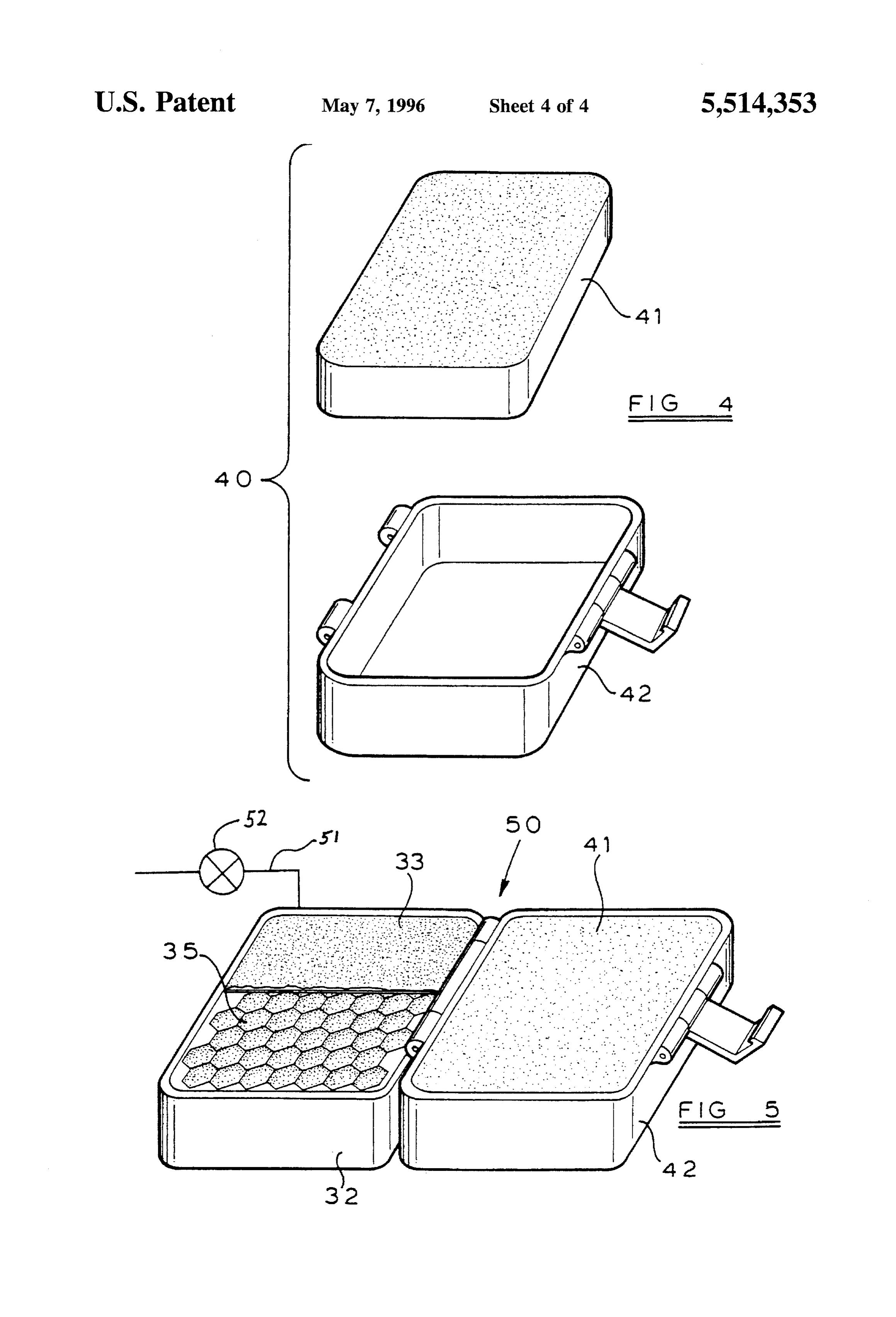
BRIEF DESCRIPTION OF THE DRAWING microporous hydrophilic membrane 33 separating these
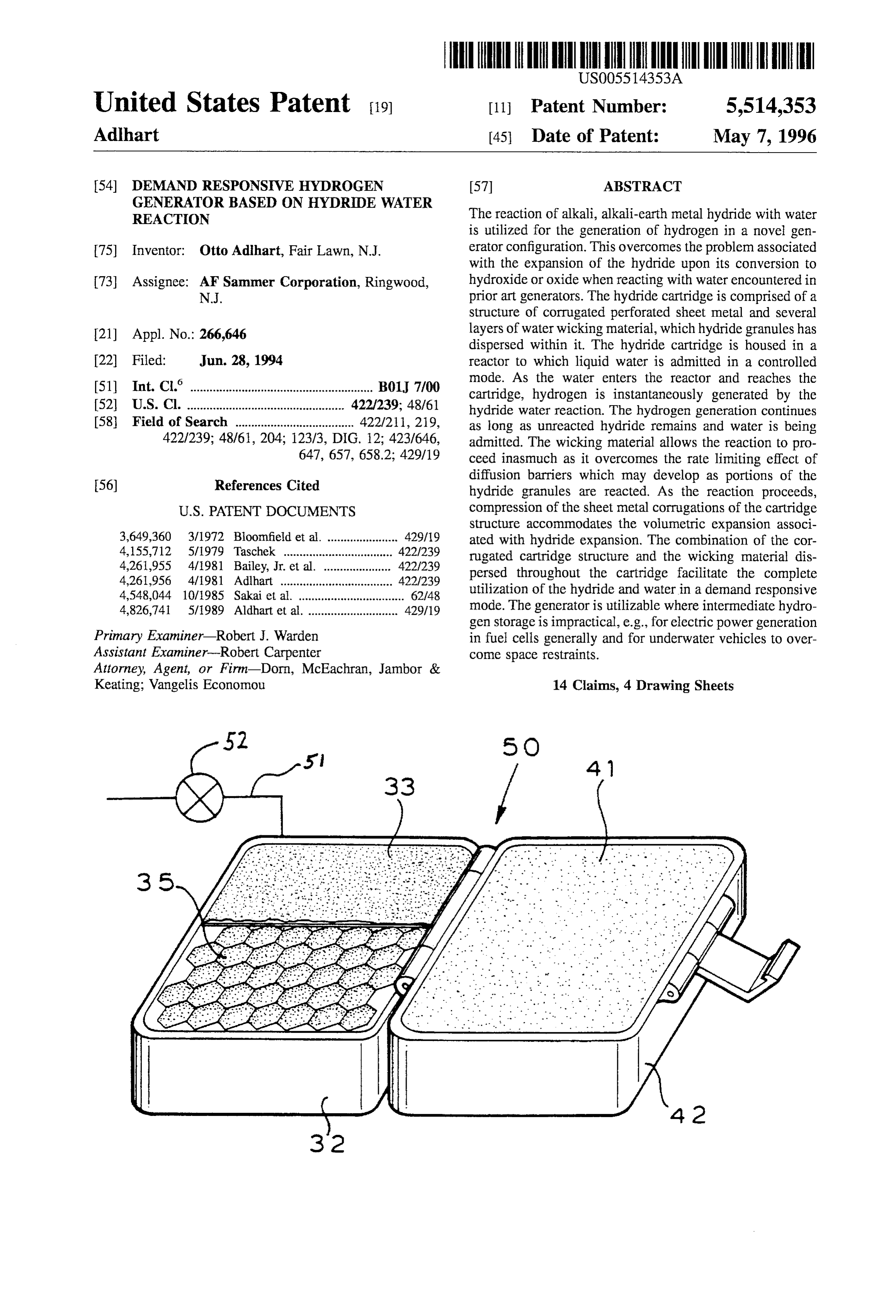
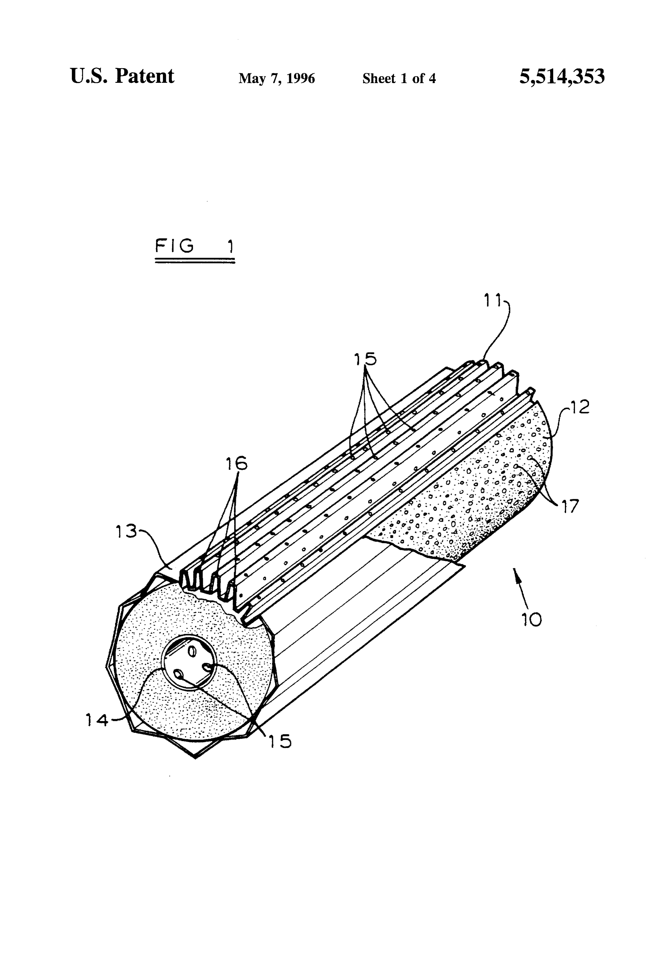
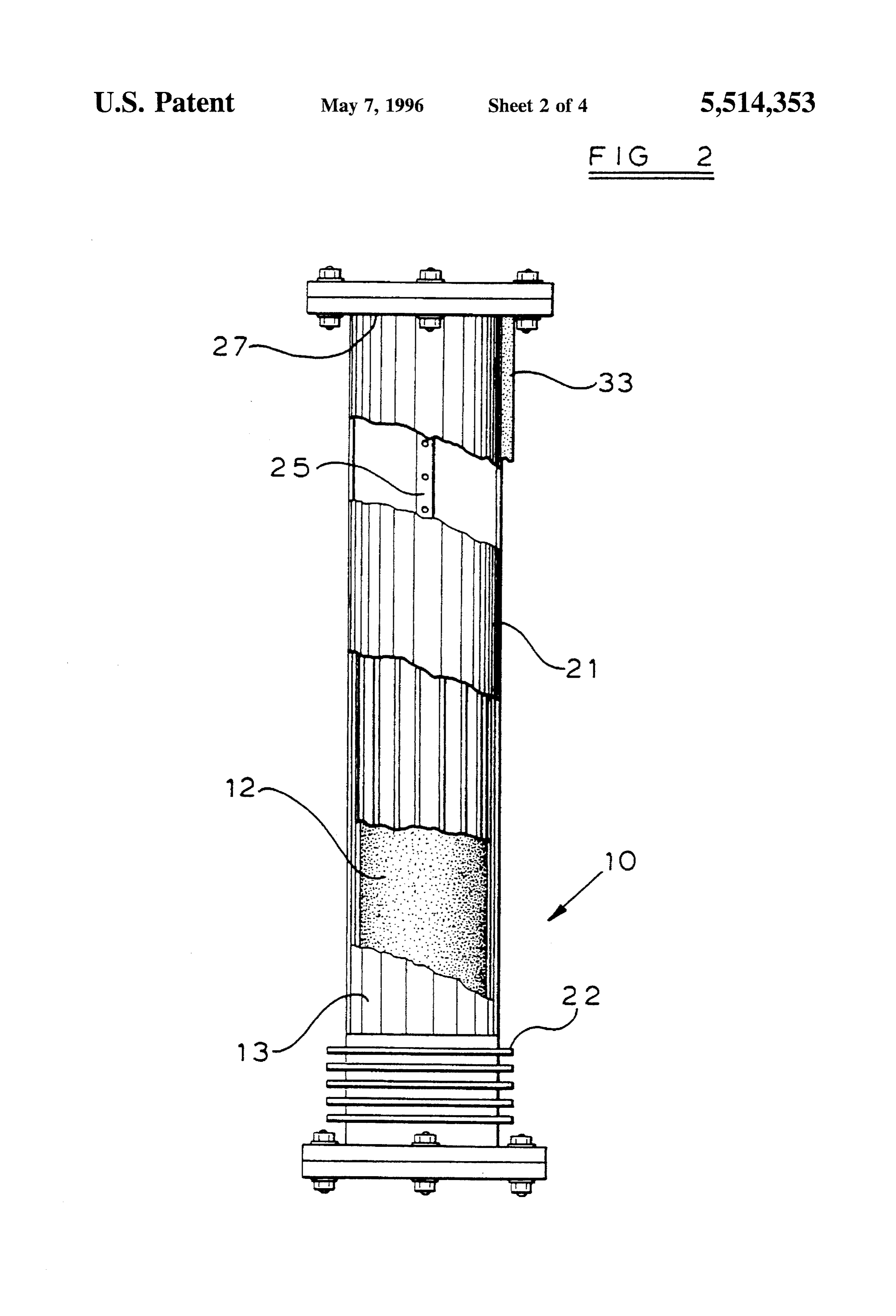
The foregoing and other features and advantages will appear more fully from drawings which accompany this EXAMPLE 1. writing and wherein: A hydrogen generator has been constructed with a hydride FIG. 1 is a perspective view of one embodiment of a cartridge as in FIG. 1, having dimensions of 6" length and hydride cartridge assembly according to the present inven 3.75" diameter using 0.006" thick magnesium foil. The foil tion, consisting of a rolled structure of corrugated and is perforated with holes 15 of 0.043" diameter. Ten percent perforated sheet metal element 1, wicking material 2, cor 10 (10%) of the foil area is removed by perforations. Subse rugated sheet metal shroud 3 and perforated water distribu quently, the foil area is corrugated with fins 16 of 0.25" tion tube 4); height with a spacing of 12 finslinch. A 6" wide 24" long foil FIG. 2 is a schematic partial cut-away view of the strip is combined with a sheet of carefully degreased graph hydrogen generator assembly consisting of the generator ite cloth 12, known as Thornel WCA and manufactured by housing, the hydride cartridge and means of water distribu 15 Amoco, having a thickness of approximately 0.02 inches, tion and/or heat dissipation; and dimensions comprising 24" length and 6" width. FIG.3 is an exploded view of a second embodiment of the Subsequently, the components are rolled up into a struc hydrogen generator according to the present invention; ture with the dimensions stated above and charged with 400 FIG. 4 is an exploded view of the water storage section 20 gm of 95% pure -30 mesh Lithium Hydride, manufactured according to the present invention; by FMC Lithium, and then surrounded by a shroud 13 of FIG. 5 is a perspective view of the integrated passive corrugated 0.005" stainless steel sheet. hydrogen generator assembly shown separately in FIGS. 3 The cartridge 10 is inserted into a stainless steel reactor and 4. purged with nitrogen to remove air before water is pumped
at an average rate of approximately 53 gm/hr. into the generator. Hydrogen was generated at an average pressure or
DETAILED DESCRIPTION OF THE 50 psig. The rate of hydrogen generation was measured in a PREFERRED EMBODIMENTS wettest meter after release from the reactor and drying of the FIG. 1 is a perspective view of a hydride cartridge hydrogen stream in a Drierite column. From the weight assembly 10 consisting of a rolled structure of corrugated 30 increase
of the Drierite, the moisture content was determined and perforated sheet metal element 11, wicking material 12, corrugated sheet metal shroud 13, and perforated water Periodically, the admission of water to the reactor was distribution tube 14. FIG. 1 shows a preferred hydride interrupted and the time interval was recorded for a signifi cartridge 10 including a plurality of corrugated perforated cant change in hydrogen pressure to take place. Conversely, sheet metal elements 11 and layers of water wicking material 35 upon readmission of water to the reactor, the time was also 12 with hydride particles 17 dispersed throughout the struc recorded that was required for a significant increase in ture. pressure to take place.
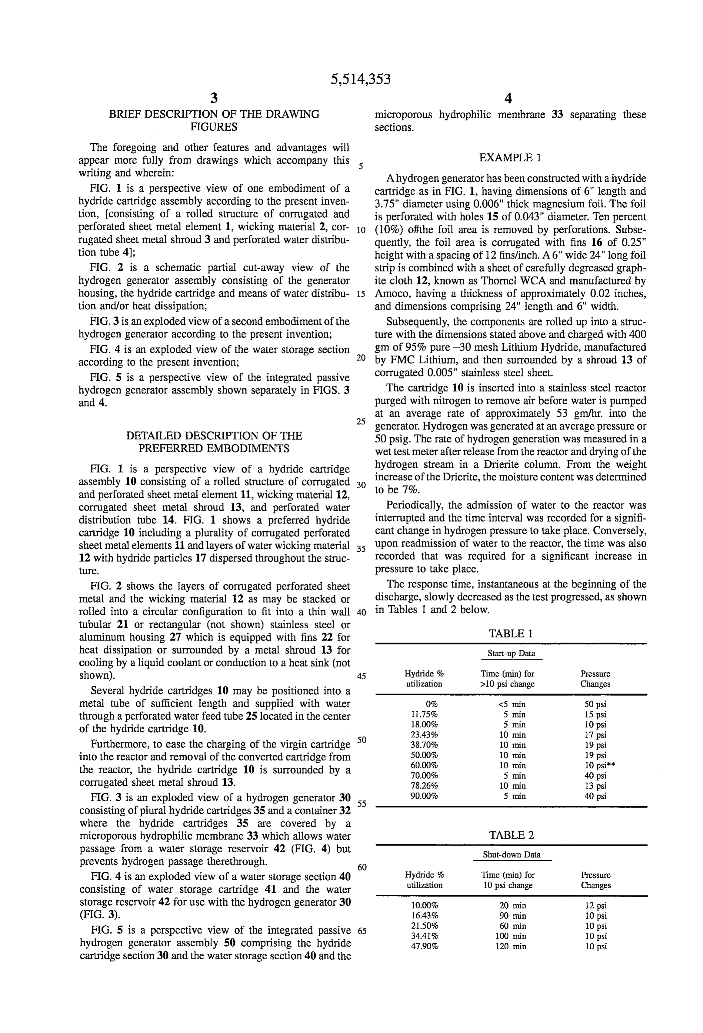
FIG. 2 shows the layers of corrugated perforated sheet The response time, instantaneous at the beginning of the metal and the wicking material 12 as may be stacked or discharge, slowly decreased as the test progressed, as shown rolled into a circular configuration to fit into a thin wall 40 in Tables 1 and 2 below.
tubular 21 or rectangular (not shown) stainless steel or TABLE aluminum housing 27 which is equipped with fins 22 for heat dissipation or surrounded by a metal shroud 13 for Start-up Data cooling by a liquid coolant or conduction to a heat sink (not shown). 45 Hydride % Time (min) for Pressure utilization >10 psi change Changes
Several hydride cartridges 10 may be positioned into a metal tube of sufficient length and supplied with water 0% <5 min 50 psi through a perforated water feed tube 25 located in the center 1.75% 5 min 15 psi of the hydride cartridge 10. 18.00% 5 min 10 psi
Furthermore, to ease the charging of the virgin cartridge 50 38.70% 10 min 19 psi into the reactor and removal of the converted cartridge from 50.00% 10 min 19 psi
the reactor, the hydride cartridge 10 is surrounded by a 70.00% 5 min 40 psi corrugated sheet metal shroud 13. 78.26% 10 min 13 psi FIG. 3 is an exploded view of a hydrogen generator 30 55 90.00% 5 min 40 psi consisting of plural hydride cartridges 35 and a container 32 where the hydride cartridges 35 are covered by a microporous hydrophilic membrane 33 which allows water TABLE 2 passage from a water storage reservoir 42 (FIG. 4) but Shut-down Data prevents hydrogen passage therethrough. 60
FIG. 4 is an exploded view of a water storage section 40 Hydride % Time (min) for Pressure consisting of water storage cartridge 41 and the water utilization 10 psi change Changes storage reservoir 42 for use with the hydrogen generator 30 10.00% 20 min 12 psi (FIG. 3). 16.43% 90 Ini 10 psi
FIG. 5 is a perspective view of the integrated passive 65 34.4% 100 min 10 psi hydrogen generator assembly 50 comprising the hydride 47.90% 120 min 10 psi cartridge section 30 and the water storage section 40 and the
Page 8
S 6 water was forced back into the water storage compartment.
TABLE 2-continued Subsequently, hydrogen was released from the reactor 50 Shut-down Data through a hydrogen release means 51 at an hourly rate of 11 liters corresponding to 20 watts, assuming a PEM cell
Hydride % Time (min) for Pressure operating point of 0.76 V/cell.
utilization 10 psi change Changes After 2 hours of operation, during which the pressure was 57.96% 150 min Opsiikk allowed to climb several times by stopping hydrogen with 63.84% 105 min 16 psi drawal by closing off the hydrogen withdrawal stopping 75.80% 20 min 10 psi means 52, the test was discontinued because the flow rate of 96.01% 60 lin 10 psi 10 11 liters/hr could not be maintained. Inspection of the reactor indicated unreacted hydride but also indicated depletion of **Indicates the time when reactor temperature was raised from 150° C. to the water in the water storage compartment.
Whereas Example 3clearly illustrated the demand (load)
The total volume of hydrogen gas generated by reacting responsive operation of the hydrogen generator, the quantity 400gm Lithium Hydride of 95% purity with water was 1075 15 of water provided for the completion of the reaction obvi liters (standard conditions). The quantity of water consumed ously has to be optimized.
was 864 gm., indicating a complete utilization of water and claim:
hydride in a stoichiometric ratio. 1. A load responsive hydrogen generator for releasing hydrogen gas from a particle hydride bed as demand for
hydrogen warrants, said hydrogen generator comprising:
a) an enclosed housing adapted for containing hydrogen
The hydrogen generator of Example 1 is tested with 298 gas under pressure, gm of 95% pure Calcium Hydride under the same conditions b) a hydride storage compartment disposed within said as in Example 1. The moisture content of the hydrogen housing for storing a mass of hydride particles dis released was measured in a MEECO Inc. moisture analyzer. 25 persed within said compartment; The moisture content was found to be less than 100 ppm. c) a liquid water storage structure removed from said The hydrogen generated increased accordingly as the hydride storage compartment, said liquid water storage residual moisture in the hydrogen released from the Lithium structure including a macroporous water absorbent Hydride containing generator is converted to Calcium material for storing liquid water, Hydroxide and hydrogen. The test was terminated after 1130 30 d) a liquid water transfer means disposed between said liters of hydrogen (standard conditions) had been generated, liquid water storage structure and said hydride storage indicating a 17% conversion of the Calcium Hydride charge. compartment for permitting passage of said liquid water from said liquid water storage structure to said
EXAMPLE 3 hydride storage compartment, said liquid water transfer means being impervious to passage of hydrogen gas
In this example Lithium Aluminum Hydride was used for 35 from said hydride storage compartment to said liquid the generation of hydrogen in the passive generator assen water storage structure while permitting passage of bly illustrated in FIG. 5. It is converted upon reaction with liquid water from said liquid water storage structure to water into Lithium Meta Aluminate and hydrogen. Four said hydride storage compartment; mols of Hydrogen are generated from each mol of Hydride. 40 e) a distribution means for receiving said liquid water Although theoretically 2 mols of water should suffice to from said liquid water transfer means and for distrib complete the conversion, in actuality twice as much water is uting said liquid water directly to said hydride particles, required because of the formation of Hydrates. thereby permitting conversion of said hydride to In Example 3, the hydride was contained in a cartridge of hydroxide and generating hydrogen gas in said hydride similar construction as in Example 1. The depth of the 45 storage compartment; and hydride bed, however, was only %" rather than 6" and 0.005" f) a hydrogen release means for releasing said hydrogen corrugated, perforated aluminum foil was used for the gas from said hydride storage compartment upon load construction of the cartridge. For water wicking, common demand.
Schleicher & Schuell Filter paper was rolled up with the 2. The load responsive hydrogen generator according to corrugated aluminum structure into a cartridge assembly of 50 claim 1 wherein said liquid water transfer means further 4" diameter. The cartridge was positioned in an Epoxy comprises a hydrophilic microporous member disposed reactor body filled with 45 g of -30 mesh Lithium Alu between said liquid water storage structure and said distri minum Hydride of 95% purity and covered with a Nylon bution means.
membrane of 2 micron pore size. 3. The load responsive hydrogen generator according to The water for the reaction was stored in a water cartridge 55 claim 2 wherein said hydrophilic, microporous member is an made up of Scott Paper Company’s “WYPALL 5701 inorganic fiber.
toweling, which was positioned in the water storage com 4. The load responsive hydrogen generator according to partment 42 of the hydrogen generator assembly 50 and claim 2 wherein said hydrophilic hydroporous member is an contained 25 g water. organic fiber.
Immediately after assembly of the hydride and water 60 5. The load responsive hydrogen generator according to sections of the passive hydrogen generator, hydrogen gen claim 1 wherein said hydride storage compartment and said eration commenced. Initially, the hydrogen was released to liquid water storage structure comprise plastic. purge any entrapped air. Subsequently, the pressure was 6. The load responsive hydrogen generator according to allowed to build up to 20 psig, considerably higher than claim 1 wherein said hydride storage compartment is a necessary for the operation of the PEM fuel cell. At this 65 disposable cartridge.
point pressure increase ceased, indicating water was kept 7. The load responsive hydrogen generator according to from entering the hydride compartment of the generator and claim 6 wherein said liquid water storage structure com
Page 9
prises a disposable water cartridge made of cellulosic fiber 11. The load responsive hydrogen generator according to and the quantity of water contained therein before hydrogen claim 1 wherein said hydride particles further comprise generation commences is in excess of that required for the lithium hydride.
complete conversion of the hydride held in the hydride 12. The load responsive hydrogen generator according to cartridge. claim 1 wherein said hydride particles further comprise 8. The load responsive hydrogen generator according to lithium-aluminum hydride.
claim 1 wherein said distribution means further comprises a 13. The load responsive hydrogen generator according to liquid water wicking member.
9. The load responsive hydrogen generator according to claim 1 wherein said hydride particles further comprise claim 1 wherein said hydride particles further comprise a 10 lithiumborohydride.
compound selected from the group of alkali and alkali-earth 14. The load responsive hydrogen generator according to metal hydrides. claim 1 wherein said hydride particles are embedded within 10. The load responsive hydrogen generator according to a wicking material.
claim 1 wherein said hydride particles further comprise calcium hydride.

Provenance
- Collection
- Cited prior art
- Original PDF
- patentimages.storage.googleapis.com →
- Filed
- 1994-06-28
- Pages
- 9
- Method
- pdftotext (the PDF's own text layer) + pdftoppm 300dpi page scans
- Source
- Google Patents bibliographic record
- Granted
- 1996-05-07
- Inventors
- Otto Adlhart; AF Sammer Corp
- Transcribed from
- patentimages.storage.googleapis.com →