patent · US4988486
Hydrogen generator
29 January 1991
Page 1 — bibliographic record
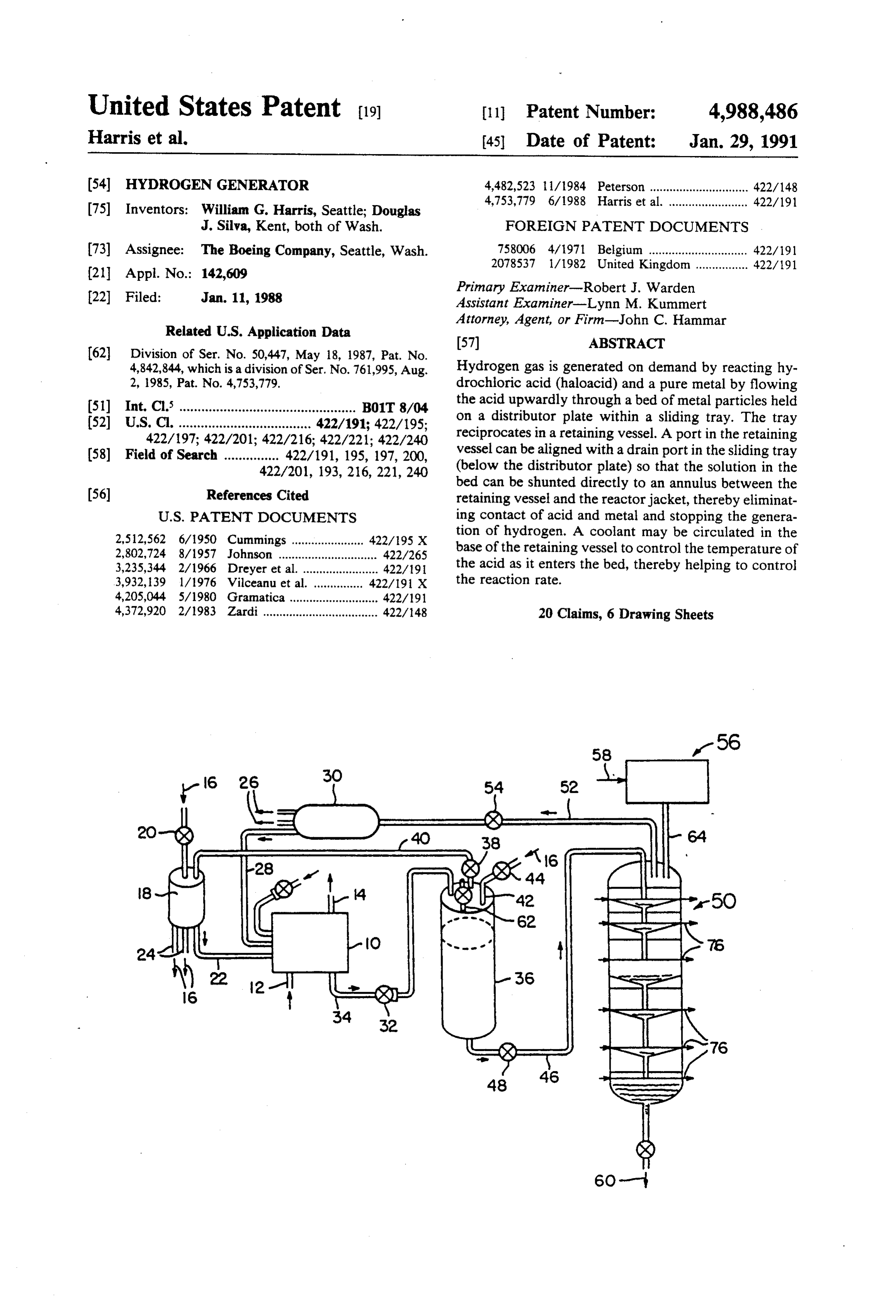
United States Patent (19) 11 Patent Number: 4,988,486 Harris et al. 45 Date of Patent: Jan. 29, 1991 (54) HYDROGEN GENERATOR 4,482,523 l 1/1984 Peterson .............................. 422/148 4,753,779 6/1988 Harris et al. ........................ 422/19 (75) Inventors: William G. Harris, Seattle; Douglas
J. Silva, Kent, both of Wash. FOREIGN PATENT DOCUMENTS (73) Assignee: The Boeing Company, Seattle, Wash. 758006 4/1971 Belgium .............................. 422/191
Primary Examiner-Robert J. Warden 22 Filed: Jan. 11, 1988 Assistant Examiner-Lynn M. Kummert Attorney, Agent, or Firm-John C. Hammar
Related U.S. Application Data
4,842,844, which is a division of Ser. No. 761,995, Aug. Hydrogen gas is generated on demand by reacting hy 2, 1985, Pat. No. 4,753,779. drochloric acid (haloacid) and a pure metal by flowing (51) Int. Cl. ................................................ B01T 8/04 the acid upwardly through a bed of metal particles held (52) U.S. C. .................................... 422/191; 422/195; on a distributor plate within a sliding tray. The tray 422/197; 422/201; 422/216; 422/221; 422/240 reciprocates in a retaining vessel. A port in the retaining (58) Field of Search ............... 422/191, 195, 197, 200, vessel can be aligned with a drain port in the sliding tray 422/201, 193, 216, 221, 240 (below the distributor plate) so that the solution in the bed can be shunted directly to an annulus between the (56) References Cited retaining vessel and the reactor jacket, thereby eliminat
2,512,562 6/1950 Cummings ...................... 422/95 X tion of hydrogen. A coolant may be circulated in the 2,802,724 8/1957 Johnson .............................. 422/265 base of the retaining vessel to control the temperature of 3,235,344 2/1966 Dreyer et al........................ 422/19 the acid as it enters the bed, thereby helping to control 3,932, 139 1/1976 Vilceanu et al. .. ... 422/191 X the reaction rate.
4,205,044 5/1980 Gramatica ..... ... 422/191 4,372,920 2/1983 Zardi ................................... 422/148 20 Claims, 6 Drawing Sheets
Page 2
Drawing sheet — no readable text.
Page 3
Drawing sheet — no readable text.
Page 4
Drawing sheet — no readable text.
Page 5
Drawing sheet — no readable text.
Page 6
Drawing sheet — no readable text.
Page 7
Drawing sheet — no readable text.
Page 8
as the acid is diluted by the reaction, the susceptance of
HYDROGEN GENERATOR the metal particles to the acid is increased to promote The United States Government has rights in this the reaction. Nearly all the HCl can be consumed. invention pursuant to Contract No. F04704-82-C-0038. The rate of reaction is controllable by cooling the
REFERENCE TO RELATED APPLICATIONS
incoming hydrochloric acid with a refrigerant, such as cooling water, that flows below the distributor plate.
This application is a divisional application based upon Each processing stage of the generator preferably United States patent application Ser. No. 050,447, filed includes a retaining vessel and an internal sliding tray may 18, 1987, now U.S. Pat. No. 4,842,844 which was a received within the retaining vessel. The refrigerant is divisional application based upon United States patent 10 introduced under the retaining vessel and creates a application Ser. No. 761,995, filed Aug. 2, 1985 now variable volume chamber between the bottom of the U.S. Pat. No. 4,753,779. vessel and the bottom of the tray. By restricting the TECHNICAL FIELD flow of refrigerant from the chamber, the tray can be The present invention relates to an improved appara 15 raised or lowered above the bottom of the vessel. A pair tus and method for generating essentially pure hydro of port (one on the vessel and one on the tray) can be gen gas on demand by the reaction of an acid with pure aligned to allow fluid within the tray to flow from the metal particles in a controlled environment. Features of tray and the vessel, draining the bed quickly and stop the reactor allow efficient and controllable operation to ping the generation of hydrogen.
produce the gas with a minimum waste. 20 The metal particles are deposited on a distributor BACKGROUND ART plate mounted in the sliding tray above the bottom to define a cavity, and hydrochloric acid is forced up
While it has long been known that hydrogen gas can wardly from the cavity through the distributor plate be generated by the reaction of acids with pure metals, and into the bed. The tray port generally communicates efficient reactors for the controlled production of es with the cavity and is on the tray wall below the distrib sentially pure hydrogen gas on an "as needed' basis 25 utor plate. HCl solution need not enter the bed when have not been pursued. For the deep basing environ stopping the reaction is desired. In this way, manufac ment of the Intercontinental Ballistic Missile program, ture of unwanted hydrogen gas is avoided. The need to however, there is incentive to optimize the method and flood the bed with a nonreactive, quenching solution to apparatus for generating hydrogen. In the deep basing slow or stop the reaction is also eliminated. Hydrogen environment, a network of tunnels, drifts, and raises 30 can be controllably generated on demand, and only a will be located far enough underground that the base minimum of hydrogen need be stored. r could survive a very large scale nuclear attack. A Surges of acid solution between stages are controlled power source that can operate without access to out with a surge control means that includes no moving side resources, particularly without the need for com parts. A pipe is filled with a plurality of tubes or stand bustion air, large scale cooling, or significant waste or 35 pipes of different diameter. The tubes project out of the by-product disposal, is essential to the survival and pipe into the internal volume of a funnel collector on post-attack usefulness or such a base. The optimized the upper end of the pipe, and #require the solution to method and apparatus of the present invention for pool in the funnel before entering the pipe. The tubes generating essentially pure hydrogen gas on a demand are positioned at different heights to regulate the flow basis uses dilute hydrochloric acid or another suitable within desired limits.
halide acid to provide a non-toxic waste product, These and other novel features of the present inven including soluble metal chlorides (or halides), and hy tion will be drogen gas that is suitable for use in a hydrogen-halide drawings andapparent by reference to the accompanying detailed description.
fuel cell. Storage of hazardous hydrogen gas is mini 45 mized. The acid is a by-product of the fuel cell oper DESCRIPTION OF THE DRAWINGS ation.
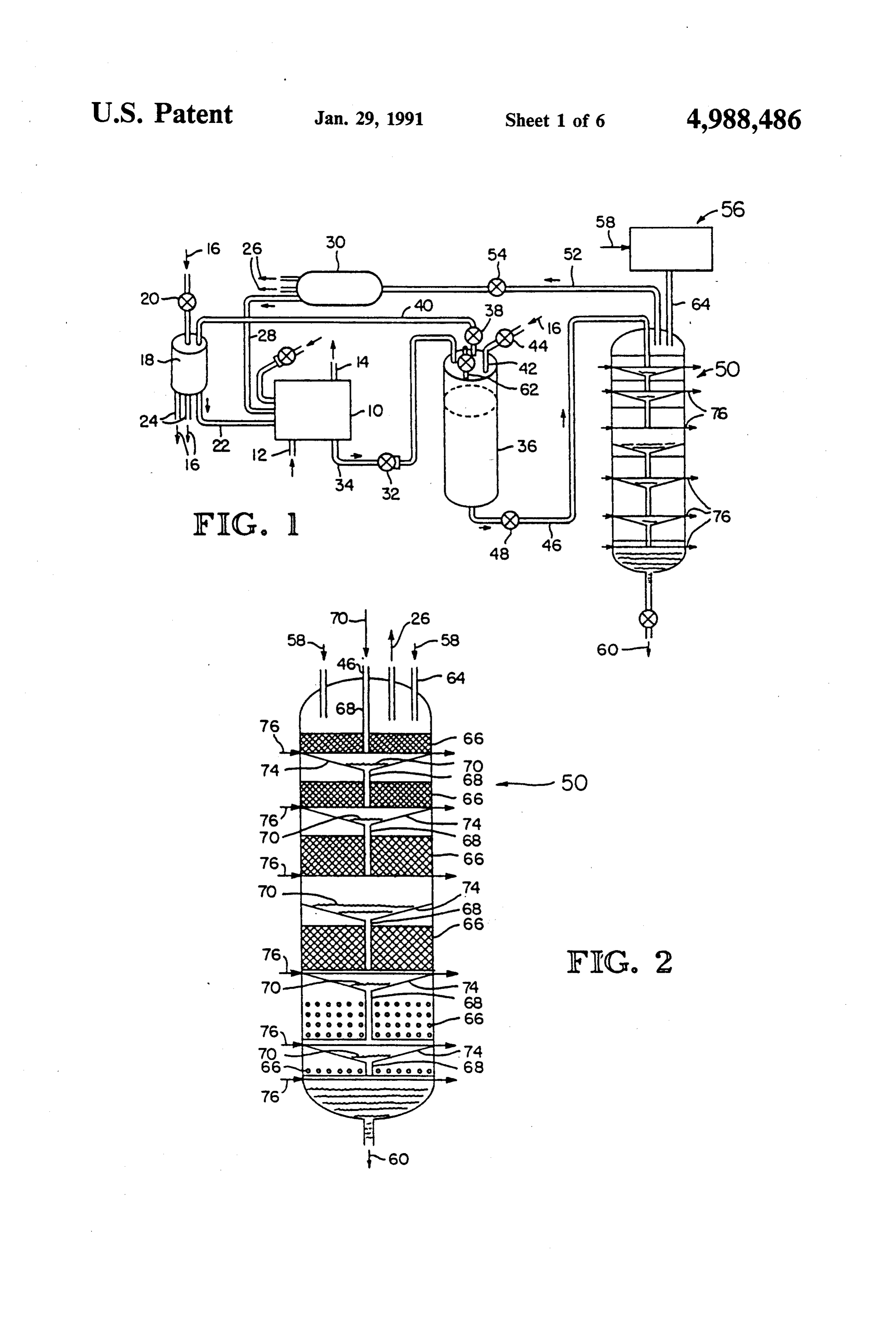
SUMMARY OF THE INVENTION FIG. 1 is a schematic of a preferred closed cycle electrical power generation system especially adapted
Essentially pure hydrogen gas can be generated in an for a deep basing environment and using the hydrogen efficient manner on demand by the reaction of hydro 50 generator of the present invention.
chloric acid with a metal. The hydrochloric acid solu FIG. 2 is a detailed schematic of the hydrogen gener tion is introduced to the bottom of a bed of essentially ator shown in FIG. 1.
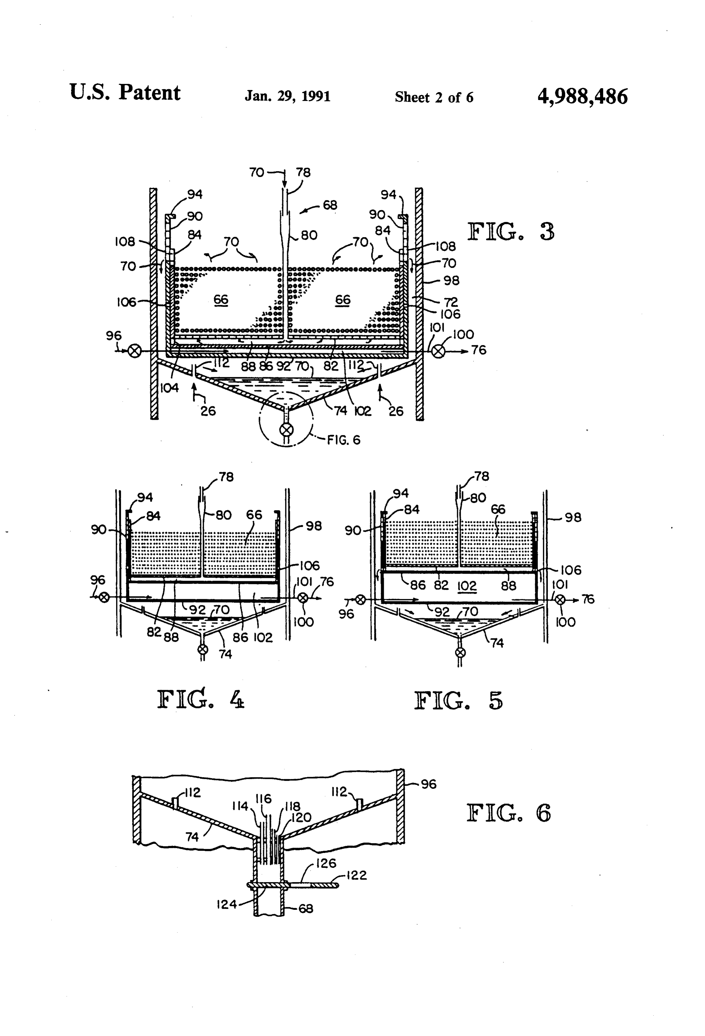
pure metal particles and is forced upwardly through the FIG. 3 is a detailed sectional view of one processing bed to promote the reaction. The flow of acid through stage of the hydrogen generator of FIG. 2. the bed should be sufficiently low to avoid fluidizing the 55 FIG. 4 is another detailed sectional view of a process particles in the bed so that all the particles remain in the ing stage, similar to FIG. 3, showing a sliding tray bed and dissolve completely. The flow is counter within the retaining vessel.
gravity so that all the metal dissolves without blocking FIG. 5 is yet another detailed sectional view, similar or clogging a distributor plate, which supports the bed. to FIGS. 3 and 4, showing the tray at a different height. In this way a substantially pure hydrogen gas stream is 60 FIG. 6 is a schematic sectional detail of the collector generated using a minimum amount of pure metal. The and surge control, generally designated by the circle in output of hydrogen gas is maximized per unit volume of FIG. 3.
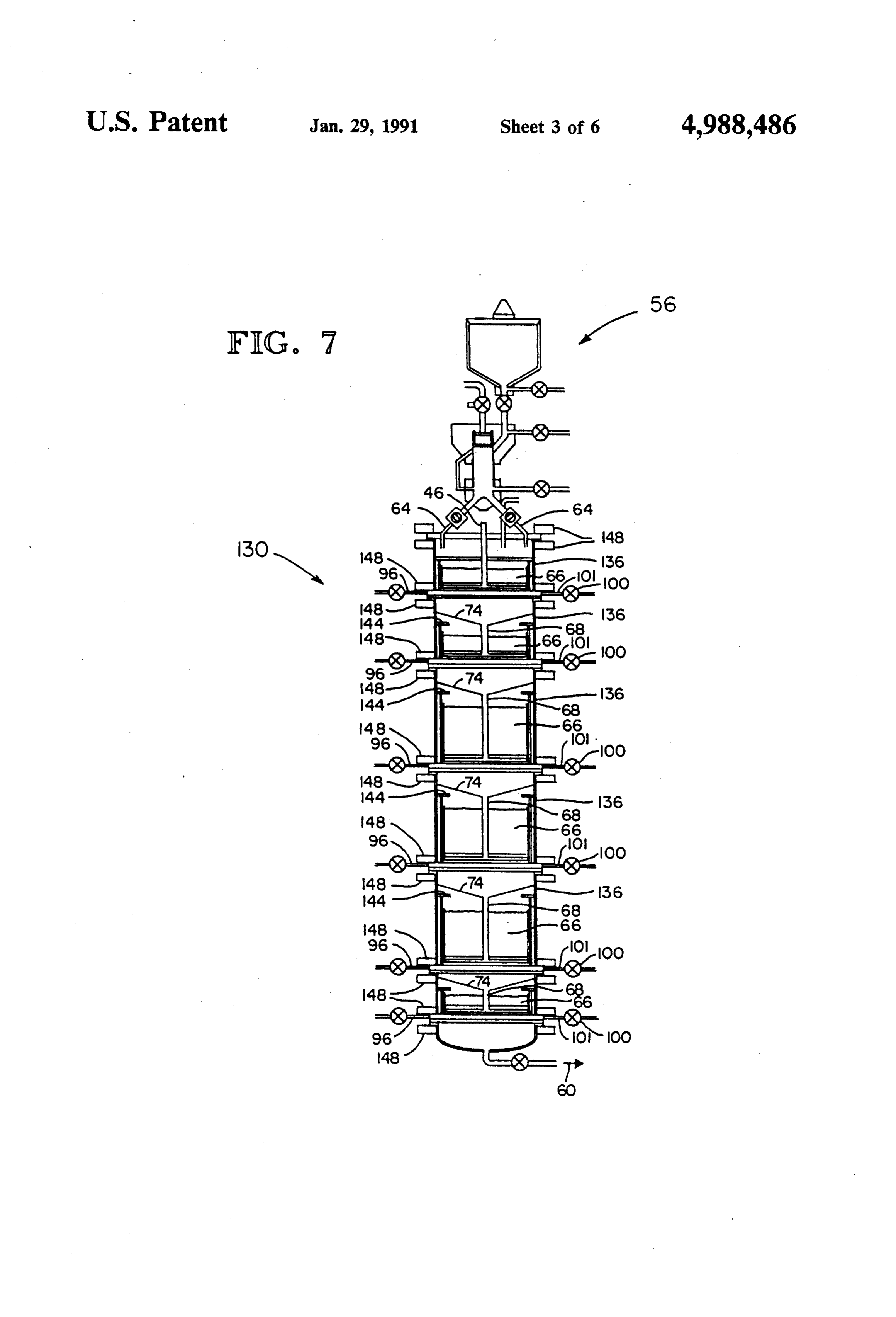
metal. The design allows metal to be added to each bed FIG. 7 is a detailed sectional schematic of another without interfering with the operation of the generator. preferred embodiment of the hydrogen generator of the The generator usually has multiple stages, with the 65 present invention.
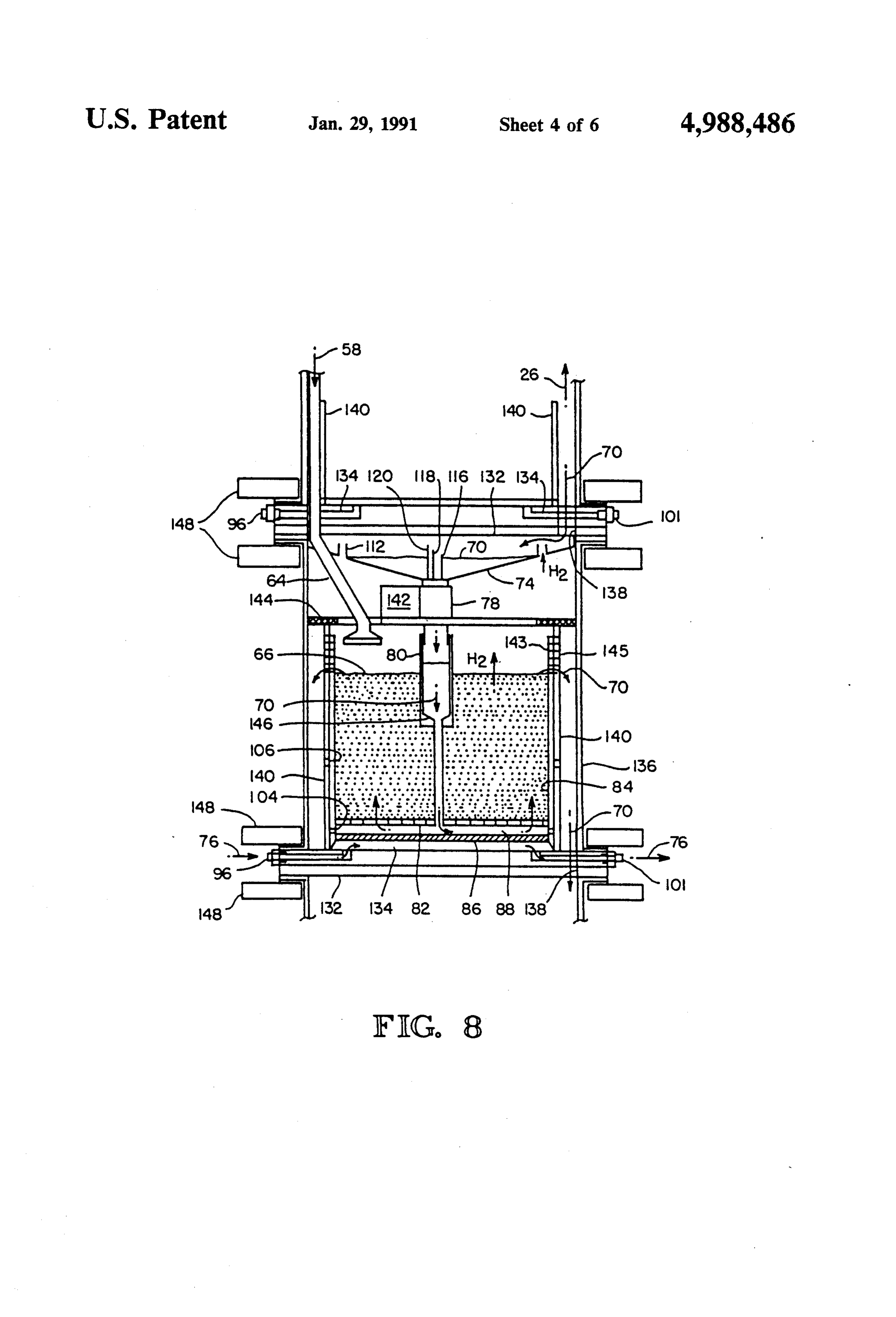
first stage having a bed of iron and a later stage, a bed of FIG. 8 is a detailed sectional view, similar to FIG. 3, zinc. Zinc has a higher reaction rate with hydrochloric showing a single processing stage of the generator of acid (by about 500 times) than the iron particles. Thus, FIG. 7.
Page 9
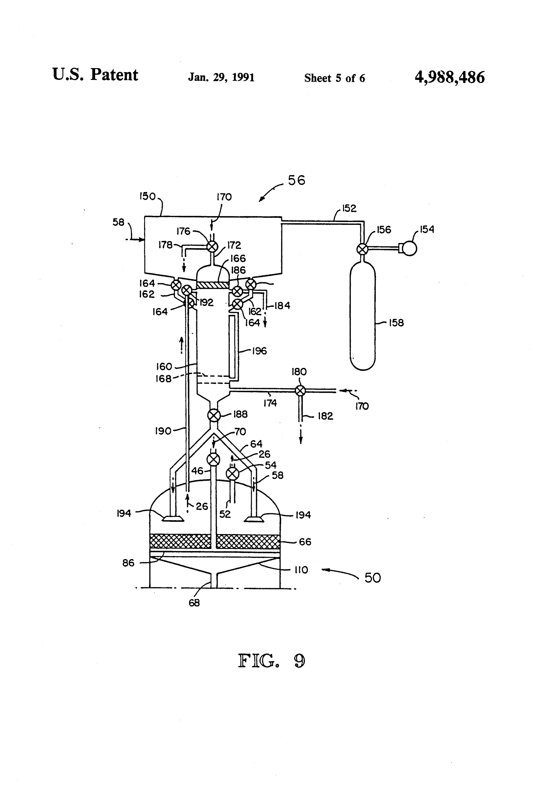
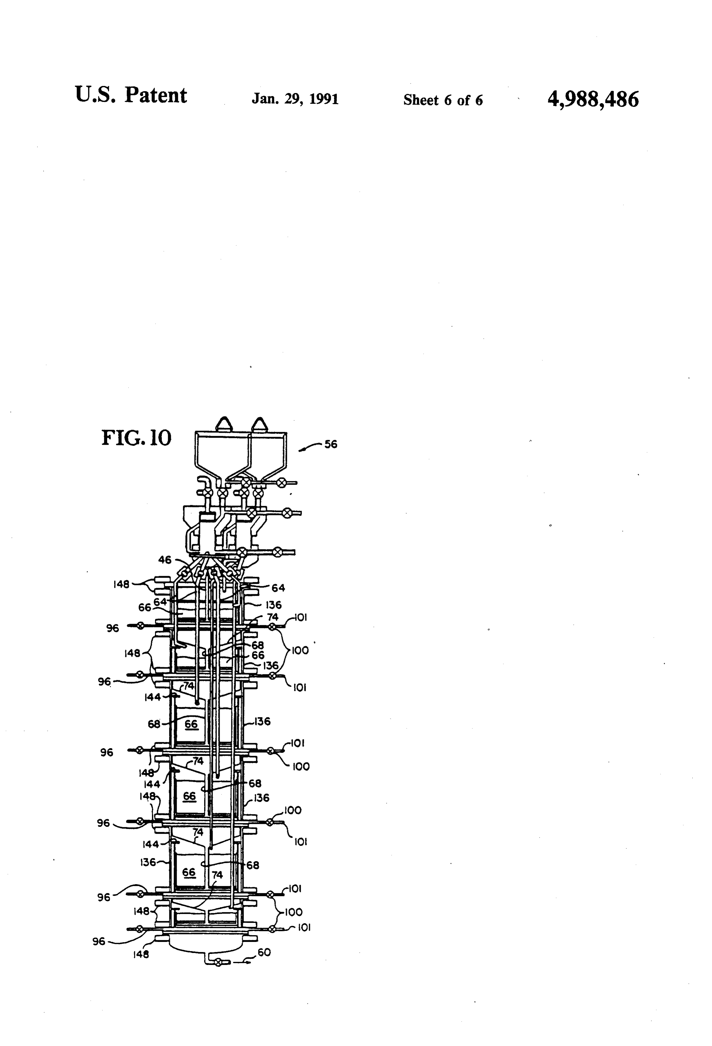
FIG. 9 is a detailed schematic of a preferred solid plentiful elements, use of hydrogen as a fuel has prog feed system for the generator of the present invention. ressed slowly because of storage and handling problems FIG. 10 is another detailed sectional schematic of the resulting from the extreme flammability of hydrogen hydrogen generator, similar to FIG. 7. over a wide range of air mixtures at ambient tempera BEST MODE CONTEMPLATED FOR tures.
CARRYING OUT THE INVENTION Power sources for underground installation would be 1. The Nature of the Problem extremely vulnerable if large amounts of hydrogen were stored. Catholytic oxidation of hydrogen in fuel
Protecting strategic systems and personnel from nu cells using oxygen or halogen gases (chlorine or bro clear weapon effects is becoming more difficult as 10 mine) appears, however, to be an efficient and preferred weapon kill effectiveness improves. One attractive con method for obtaining electrical energy in closed cycle cept for such protection, known as deep basing, would underground systems. The most efficient fuel cell locate the facilities several thousand feet underground. power system for the underground installations is prob These deep basing environments, however, create ably a hydrogen-chlorine fuel cell, under development unique problems associated with the close-cycle living 15 by Hamilton Standard Electro-chem, Inc., a division of environment that is necessary for survival. Essential to United Technologies Corp., which produces electricity the survival and post-attack usefulness of such a base is and by-product HCl.
a power source that can operate in this environment The present invention uses the by-product hydro without access to outside resources, such as combustion air, sources of cooling, or large capacity waste disposal thereby acid 20 chloric to recycle the hydrogen safely and easily, alleviating any storage problem for hydrogen in facilities, especially of hazardous wastes. The power the deep basing environment. The unit can be com system, particularly for electrical energy, must be pactly designed to minimize the length of hydrogen readily packaged, be shock isolated, and, most impor lines and allow isolation of the entire system on a shock tant, be efficient. Storage of hazaraous materials (reac tants, intermediates, or wastes) should be avoided. The 25 isolation platform, if desired. system should be capable of laying dormant for ex 2. The Power System tended time periods without degradation.
As described in a paper by William Harris entitled As shown in FIG. 1, the deep basing closed cycle "Chlorine as an Oxidizer for a Closed Cycle Power power system includes a hydrogen-chlorine fuel cell 10 Plant,' delivered Feb. 13, 1985, a hydrogen-halide fuel 30 having a cooling water inlet 12 and outlet 14 for con cell is the best candidate for generating electricity for trolling the reaction of chlorine and hydrogen within deep basing. Safe storage and handling of the reactants, the fuel cell 10. Chlorine 16 enter a distributor 18 hydrogen and halogen, however, is a primary concern through a check valve 20 from liquid storage and enters to the implementation of a hydrogen-halide fuel cell. the fuel cell 10 through a feed line 22. Other lines 24 the One feature of the present invention relates to a hydro 35 distributor 18 direct chlorine 16 to other cells (not gen generator that is capable of creating hydrogen on shown) in the power system.
demand from by-products of the fuel cell, and that virs Hydrogen 26 enters the fuel cell 10 through a feed tually eliminates the hazard of storing hydrogen gas. line 28 from an accumulator 30, which also distributes Safety considerations dictate that large quantities of the hydrogen 26 to the other cells. Electricity and heat hydrogen gas cannot be stored in the deep basing envi 40 are generated in the fuel cell 10. A waste product com ronment. Hydrogen can be safely generated by the prising hydrochloric acid in water and unreacted chlo reaction of dilute hydrochloric acid (a by-product of rine enters a pump 32 through line 34, and is pumped the fuel cell operation) on a pure metal. Although a into a receiver 36 for the separation of chlorine gas from large selection of cations can be used as fuel for the the acid solution. The gaseous chlorine is recycled hydrogen generator, selection of the fuel is dictated by 45 through the check valve 38 and return line 40 to the several considerations. For example, the fuel should be chlorine distributor 18. Chlorine 16 may, alternatively, plentiful, should be readily available in a form that is be added to the receiver 36 through line 42 and check easily used, and should be inexpensive. The heat re valve 44 to increase the concentration of the acid solu leased during the exothermic reaction between the acid tlOn.
and the metal should be as low as possible to minimize 50 The dilute hydrochloric acid solution leaves the re heat sink requirements. Finally, the waste products ceiver through line 46 and flow regulator 48, and enters created in the reaction should remain soluble in water to the first stage of the hydrogen generator 50, the details allow easy removal and storage. Based upon these con of which will be described. Essentially pure hydrogen ditions, iron is the preferred metal, because it is readily gas, created in the hydrogen generator 50, is diverted available in pellet form, has a low heat of reaction with 55 through line 52 to the hydrogen accumulator 30 hydrochloric acid, and is inexpensive. Zinc is preferred through a flow regulator 54. A solid fuel feed system 56 for secondary reaction beds (where the acid is diluted), allows the addition of metal particles 58 to the several since zinc has a reaction rate with hydrochloric acid of beds 66 of the hydrogen generator 50 without contami about 500 times greater than that of iron. Both zinc and nating the controlled environment of the generator. iron chlorides are compatible for the waste product 60 A waste stream 60 is withdrawn from the bottom of solution, even when mixed. Although iron and zinc are the hydrogen generator 50, and includes a solution of preferred, other metals may be used, such as lead or metal chlorides in water with a trace of hydrochloric copper.
Hydrogen as a primary fuel is becoming increasingly acid. This waste stream 60 is stored in suitable storage facilities, such as within a raise of the base that was attractive as fossil fuel supplies dwindle Hydrogen has a 65 originally used to store water. very high thermal heating value of about 60,000 BTU's During transit conditions, if excess hydrochloric acid per pound compared to about 20,000 BTU's per pound is generated in the fuel cell 10 during consumption of for fossil fuels. Although hydrogen is one of the most hydrogen, this excess acid solution raises the pressure
Page 10
within the receiver 36 and opens check valve 38 to The sliding tray 84 is received within a retaining allow chlorine to flow into the fuel cell distributor 18 vessel 90 to create a fluid seal between the side of the through line 40, thereby maintaining the pressure within tray 84 and the wall of the vessel 90. As illustrated in the receiver 36. The small amount of HCl which is FIGS. 3, 4, and 5, the tray can move upwardly and removed in the waste stream 60 is replenished to the downwardly in the vessel 90 between the bottom of the system through line 62 in the receiver 36. vessel 92 and an end-of-motion limit 94 on the open end As shown in FIG. 10, the solid fuel feed system 56 of the vessel.
includes one or more fuel distribution lines 64 which Cooling water 76 entering the retaining vessel 90 direct the solid fuel to the reaction beds 66 within the through a feed line 96 in the outer jacket 98 can be used generator 50. For clarity, the distribution lines 64 have O to lift the sliding tray 84 by restricting flow of the water been truncated in FIGS. 1, 2, and 7, and have been from the vessel with a back pressure valve 100 on the deleted entirely in FIGS. 3, 4, and 5. outlet 101. The cooling water 76 within the retaining vessel 90 defines a chamber 102 between the bottom of 3. The Generator the tray 86 and the bottom of the vessel 92 that has a
A preferred hydrogen generator 50 is illustrated sche 15 variable volume. When this chamber 102 is increased in matically in FIG. 2 where the reaction of hydrochloric volume (raising the sliding tray 84), a port 104 on the acid with metal particles is carried out in six process tray can register with a drain port 106 intermediate stages by flowing the hydrochloric acid progessively within the wall of the retaining vessel 90 so that the acid through six beds 66. The top four beds in the vertical 20 solution 70 does not enter the bed 66, but flows directly stack of the hydrogen generator 50 are illustrated with from the cavity 88 through the aligned ports 104 and patched lines designating that these beds contain iron 106 into the annulus 72 between the retaining vessel 90 particles, while the beds of the lower two processing and the outer jacket 98. Any fluid remaining in the bed stages are designated by circles to indicate that these also will drain hydrostatically back through the distrib beds contain zinc. The depth of particles in each bed is 25 utor plate 82 into the cavity 88 and out the aligned ports controllable to control the residence time of acid within 104 and 106 into the annulus 72 so that the reaction may each bed, thereby controlling the heat and hydrogen be quickly stopped.
gas that are created. One or more ports 108 near the top of the wall of the Each processing stage of the hydrogen generator 50 retaining vessel 90 above the top of the tray allow acid includes a centrally located downcomer 68 which deliv solution 70 that emerges from the bed 66 to drain into ers the hydrochloric acid solution 70 to the bottom of 30 ing the annulus 72 without passing over the lip of the retain vessel.
each bed where the solution 70 flows upwardly through Fluid in the annulus 72 falls to a funnel collector 74 the bed 66 to create hydrogen during contact with the metal. Emerging from the top of the bed, the solution and pools there due to a surge control means which will be described. The collector 74 preferably includes a passes into an annulus 72 (FIG. 3) to a collector funnel 35 plurality 74 that leads to the downcomer 68 for the next lower of necked openings 112 to allow passage of gas stage. 26 upwardly through the several stages of the generator Cooling water 76 flows across the base of each stage 50,The surge control means is more completely shown to cool the acid solution to control the reaction rate further. The waste stream 60 accumulates in the bottom in FIG. 6. As illustrated there, the downcomer 68 is of the generator 50 and may be scrubbed prior to pump filled with plurality of tubes or standpipes 114, 116, 118, and 120 having different diameters and being positioned
Each processing stage of the hydrogen generator will at different heights above the base of the funnel collec now be described in greater detail with reference to before tor 74 so that solution must pool on the collector 74 FIGS. 3, 4, and 5. it enters the downcomer 68. If a surge of solution 45 were to enter the funnel collector 74 (as by raising the
The downcomer 68 preferably has two sections sliding which telescope together as illustrated by the straight 106) thetray of an upper stage to align the ports 104 and
section 78 and bell receiving section 80 in FIG. 3. The surge or solution from reaching the next stage. The telescoping sections allow the length of downcomer 68 to be varied, as will be explained. The bell section 80 50 surge control means, having no moving parts, protects against inadvertent introduction of acid to the beds passes through the bed 66 and through a distributor during transit conditions (start-up, shutdown, loading, plate 82 mounted within a sliding tray 84. The distribu etc).
tor plate 82 has a plurality of holes to allow the passage go' valvedowncomers
of the hydrochloric acid solution 70 upwardly through downcomer122 having a first portion 124 to seal the the distributor plate 82 and into the bed 66. The distrib 55 126 to allow 68unrestricted an a second portion having an opening flow of solution through the utor plate 82 is positioned slightly above the bottom 86 downcomer 68. This valve allows complete shut-off of of the sliding tray 84 to define a cavity 88 between the lower stages in the generator.
bottom 86 and the plate 82. The cavity allows uniform FIGS. 7 and 8 illustrate an alternative preferred em distribution of the acid solution across the bottom of the bed 66, which rests above the distributor plate. Thus, number bodiment of the present invention. Identical reference the hydrochloric acid solution flows countergravity embodiments. are used to identify analagous parts between the through the bed 66 at a flowrate and velocity slow 7) includes sixAgain, the hydrogen generator 130 (FIG. enough to avoid fluidizing the particles of the-bed so generate hydrogen gas instacked beds 66 within the reactor to that (1) optimum reaction conditions are achieved, (2) beds 66 within the reactor usually arestages. successive filled
The upper with pure the particles are completely dissolved, and (3) no parti 65 iron particles while the lower beds contain zinc. cles are entrained in the solution or are carried from the The differences in construction between the two bed. The maximum amount of hydrogen is created from embodiments is best understood with reference to FIG. the minimum amount of metal. 8. Each processing stage includes a base 132 that in
Page 11
cludes an internal channel 134 for the circulation of metal particles. The gas is used in the hopper to prevent cooling water 76 from an inlet 96 to the outlet 101. The any damaging oxidation of the metal particles while base 132 also includes a through-hole 138 on one side of they are stored in the hopper prior to injection into the the base to allow the passage of acid solution 70 down hydrogen generator 50.
wardly through the base to the next processing stage 5 and hydrogen gas 26 upwardly to the bonnet at the top 160The receiving hopper 150 is connected to an injector with one or more conduits 162 that allow metal of the generator 130. particles within the receiving hopper 150 to be fed by The channel 134 has two segments within the base gravity or otherwise to the injector 160. Each conduit and a portion of variable volume defined by the base 162 preferably includes two or more valves 164 which 132 and the bottom 86 of a sliding tray received be O tween the walls 140 of a receive or retainer vessel (gen can ing be closed to isolate the injector 160 from the receiv hopper 150. These valves 164 are particularly im erally being a 12 inch diameter teflonlined pipe) affixed portant to alleviate hydrogen leakage between the in to the base 132. A top plate or retaining ring 144 seats jector and the receiving hopper. on the wall 140 and serves as a stop limit for movement The injector 160 is generally cylindrical, and includes of the sliding tray relative to the base 132 within the 15 a piston 166 that can reciprocate within the injector vessel.
between the upper
A distributor plate 82 mounted within the sliding tray 9 and a lower position position shown in solid lines in FIG. above the bottom 86 creates a cavity 88 into which the schematically illustrated by the dotted lines 168 downcomer 68 (made of telescoping sections 78 and 80) 166 is achieved by injectingin FIG. 9. The movement of the piston delivers hydrochloric acid solution 70 for distribution 20 166 through a port 172 at thewater 170 behind the piston top of the injector 160 or upperwardly through the distributor plate 82 into the beds 66. The bell section 80 of the downcomer 68 may an exhaust port 174 near the bottom of the injector. A include an internal funnel 146 to further control flow of control valve 176 in the water infeed line above the port acid 70 to the cavity 88. The telescoping sections 78 and 172 allows the flow of water to be controlled and allows 80 allow the sliding tray to move relative to the base 132 25 fluid to be diverted from the injector through the port and relative to the collector 74 of the next higher stage 172 to an exhaust line 178 to drain the injector when the piston moves from the lower position 168 to the upper in the generator 130.
Drain ports 104 and 106 allow the rapid draining of position.
the reactor bed by shunting fluid directly from the cav Similarly, a control valve 180 connected with the ity 88 to the through-hole 138. 30 exhaust port 174 allows the water 170 to be shut off, and Pipe flanges 148 connect the base plates 132 to each the injector 160 to communicate with a waste line 182 section of the outer jacket 136 (formed from a 16 inch for draining.
diameter TEFLON lined pipe). As can be seen by com An overflow drain 184, including a flow control parison of FIGS. 3 and 8, the major difference between valve 186 is connected to the injector 160 above the the two embodiments of the generator is that in one 35 connecting conduits 162 to allow draining of water 170 (FIG. 3) the retaining vessel is mounted within the from the injector when metal particles are transferred outer jacket 98, while in the other (FIG. 8) the base 132 from the receiving hopper 150 to the injector 160. En and jacket 136 together form the structure of the gener trained gas that is conveyed to the injector from the ator. receiving hopper by the particles is of a lower density This embodiment allows the number of trays within than the water within the injector, rises to the top of the the generator to be varied, since each processing stage injector, and is bled from the injector through the drain is separable from the stack. Consequently, however, the 184. The metal particles displace water within the injec possibility of leaks is increased, since there are a greater tor and form a mixture of the metal particles and water number of seals. only.
Drain ports 143 and 145 in both the tray 84 and vessel 45 A valve 188 at the bottom of the injector 160 isolates walls 140 are necessary in a second preferred embodi the injector from the generator 50, and allows the injec ment to allow acid 70 to reach the passageway leading tor to be filled with water 170 through line 174 prior to to the through-hole 138. transfer of metal particles 58 from the receiving hopper A water powered TEFLON shut-off valve 142 is 150 to the injector 160, as as has been described. With positioned in the downcomer 68 to help control flow of 50 metal particles in the injector, the control valves 164, acid between stages. 180, and 186 are closed, and hydrogen gas 26 passes Referring to FIG. 9, the preferred solid fuel feed from the generator 50 to the injector through line 190 system will now be described. by opening a control valve 192 in the line 190. The gas The system 56 includes a receiving hopper 150 hav 26 enters the injector 160 near the upper end of the ing an inlet (not shown) to allow introduction of metal 55 injector in the vicinity of the drain 184. With the valve particles 58 into the hopper 150 when the hopper is 192 open, the control valve 180 is opened to allow the vented to the atmosphere. The hopper 150 is connected entering gas to drive the water between the particles in through vacuum line 152 to a vacuum pump 154, which the injector out he waste line 182, leaving a combination may be used to evacuate the hopper 150 to a pressure of of metal particles, hydrogen gas, and a small amount of about 1 psia or less, after the introduction of the metal 60 entrained water within the injector. Then, the control particles to the hopper. The vacuum line is also con valve is closed and the valve 188 is opened. Water pres nected through a two position valve 156 to a reservoir sure is created behind piston 166 to drive the piston 158 of an inert gas, such as nitrogen. Following evacua downwardly in the injector and to force metal particles, tion of the hopper, the vacuum pump 154 is stopped, entrained gas, and water through fuel supply lines 64 and the valve 156 is opened to allow a positive pressure 65 into the generator 50. Distributor heads 194 rotate of gas to enter the receiving hopper 150 from the reser under the pressure of the metal particles in the supply voir 158. This gas should be relatively insoluble in lines 64 to distribute the particles uniformly over the water and should be essentially nonreactive with the beds 66.
Page 12
A sight glass 196 on the side of the injector allows the 7. The reactor of claim 6 further comprising second operator to know the level of liquid in the injector 160 active cooling mans in fluid communication with the by viewing the meniscus between the liquid and gaseous bottom of the second vessel for controlling the tempera phases. ture of the vessel and, thereby, both the temperature of While preferred embodiments of the invention have the solution and the reaction rate between the solution been shown and described, those skilled in the art will and metal particles.
readily recognize alterations, modifications, or varia 8. The reactor of claim 7 wherein the first and second tions that might be made to the preferred embodiments active cooling means each include a flow regulator for without departing from the inventive concept. The controlling the flow of a coolant through each respec description and drawings are meant to illustrate the O tive cooling means, the flow of coolant varying the invention and not to limit it. The claims should be inter relative position of the associated vessel in the reactor preted liberally in light of the description and drawings jacket.
to protect the invention as described in the preferred 9. The reactor of claim 1 wherein the first active embodiments and their full range of equivalents. The cooling means includes a flow control regulator for claims should only be limited as is necessary in view of 15 controlling the flow of a coolant through the cooling the pertinent prior art. means, and, thereby, for controlling the degree of cool We claim: ing available to control the reaction rate. 1. A reactor for generating hydrogen, comprising; 10. The reactor of claim 1 further comprising metal (a) a reactor jacket; feed means for introducing metal particles to the bed of (b) a first vessel, positioned in the reactor jacket, for 20 the first vessel during operation of the reactor. holding a first bed of consumable metal particles on 11. The reactor of claim 1 further comprising means a distributor plate, the vessel having a bottom; for quickly draining solution from within the first vessel (c) means for introducing an HCl solution to the to the funnel.
vessel through the distributor plate so that the 12. A reactor for generating hydrogen, comprising; solution flows upwardly counter to gravity 25 (a) a reactor jacket defining an enclosed reaction through the first vessel; volume, the jacket having a longitudinal axis; (d) first active cooling means, positioned below the (b) a first vessel movably mounted within the reactor distributor plate in fluid contact with the bottom of jacket for motion in the direction of the longitudi the vessel, for cooling the vessel, and thereby, nal axis;
controlling the temperature of the solution and the 30 (c) a distributor plate within the first vessel; rate of reaction between the HCl solution and (d) a first bed of consumable metal particles lying on metal particles to produce hydrogen, the cooling the distributor plate;
means having an inlet and outlet in the reactor (e) means for introducing an acid solution to the first jacket; vessel and for forcing the solution through the (e) means for collecting the hydrogen produced in 35 distributor plate and first bed in counter gravity the vessel; and flow to allow the solution to react with the metal (f) means for collecting the solution emerging from particles to produce hydrogen; the vessel, the solution collecting means including (f) first active cooling means in contact with the first a funnel substantially spanning across the reactor vessel for cooling the solution prior to passage of jacket, the funnel having slated, converging walls the solution through the distributor plate and into for directing the collected solution under gravity the first bed, the cooling means including a coolant flow to a substantially central downcomer port. flow regulator for controlling the delivery of cool 2. The reactor of claim 1 further comprising a second ant and, thereby, for controlling the rate of reac vessel positioned within the reactor jacket for holding a tion between the solution and the metal particles second bed of consumable metal particles and means for 45 and the relative position of the first vessel in the introducing the solution from the funnel to the second reactor jacket;
vessel. (g) metal feed means for introducing metal particles 3. The reactor of claim 2 further comprising consum to the first bed during operation of the reactor; able metal particles on each of the beds, wherein the (h) means for collecting hydrogen produced by the metal particles of the first bed are iron and the metal 50 reaction of the solution and metal particles in the particles of the second bed are zinc. first bed;
4. The reactor of claim 2 wherein the first bed is (i) means for quickly draining the solution from the stacked in the reactor jacket above the second bed and first bed, including a drain port in the first vessel, wherein the funnel is mounted between the first and wherein adjusting the flow of coolant moves the second beds. 55 first vessel to register the drain port with a solution 5. The reactor of claim 4 further comprising passive outlet positioned on the reactor jacket; and surge control means, disposed adjacent to the down (j) solution collection means for collecting the solu comer port of the funnel, for controlling the rate of tion emerging form the bed or from the solution solution flow through the port, wherein the port is in outlet, the solution collection means including a fluid communication with the means for introducing the 60 funnel mounted across the reactor jacket, the fun solution to the second vessel. nel having slated, converging walls for directing 6. The reactor of claim 5 wherein both the first vessel the solution under gravity flow to a substantially and the second vessel are movably mounted within the central downcomer port.
reactor jacket, and wherein the means for introducing 13. The reactor of claim 12 further comprising at least solution to the second vessel includes a telescoping 65 a second vessel positioned in the reactor jacket to re conduit connected to the downcomer port for compen ceive solution from the downcomer port, a second bed sating for relative motion between the funnel and the of metal particles in the second vessel, means for forcing second vessel. solution through the second vessel counter to gravity
Page 13
and second active cooling means for cooling the solu (g) at least one throughhole passing through the base tion prior to entry of the solution to the second bed and plate, the throughhole being isolated from the cav after leaving the funnel. ity, inlet channel and exit channel; 14. The reactor of claim 13 wherein the first and (h) means for introducing coolant to the cavity second active cooling means each supply coolant to through the inlet channel and for withdrawing cool the bottom of the associated vessel. coolant from the cavity through the exit channel, 15. The reactor of claim 13 further comprising pas the means including a back pressure valve in fluid sive surge control means disposed adjacent to the communication with the exit channel; and downcomer port for controlling flow of solution from (i) a collector funnel spanning between the walls of the funnel to the second vessel. O the outer jacket for receiving the solution that 16. The reactor of claim 13 wherein the second vessel passes through the sliding vessel and throughhole; is movably mounted in the reactor jacket for movement wherein the relative position of the sliding vessel along the longitudinal axis and further comprising a within the fixed vessel is controlled by controlling telescoping conduit connecting the downcomer port 15 the flow of coolant supplied to the cavity. and the second vessel for compensating for relative 18. The reactor of claim 17 further comprising means motion between the funnel and second vessel, wherein for supplying metal particles to the sliding vessel. the second active cooling means includes a flow regula 19. The reactor of claim 18 further comprising at least tor and the relative position of the second vessel is one drain port in the sidewall of the sliding vessel posi controlled by controlling the flow of coolant in the 20 tioned between he bottom wall and the distributor plate. second active cooling means using the flow regulator. 20. A reactor for generating hydrogen by the reaction 17. A reactor for generating hydrogen, comprising: between an acid solution and metal particles, compris (a) an outer jacket; ing:
(b) a base plate including an inlet channel for coolant (a) a vessel for supporting a bed of metal particles; and an exit channel, the plate spanning between the 25 (b) (c) a bed of metal particles in the vessel;
means for supplying the acid solution to the bed, sidewalls of the jacket;
(c) a fixed vessel mounted to the base plate; the means forcing the solution in countergravity (d) a sliding vessel received within the fixed vessel, flow through the bed;
the sliding vessel including a bottom wall mounted (d) means for cooling the bottom of the vessel, and, so that when the sliding vessel sits on the base plate 30 othereby, the acid solution before entry to the bed a cavity is defined between the base plate, bottom and for creating a thermal gradient across the wall, and depending sidewalls of the sliding vessel, depth of the bed, the means including a cavity in wherein the inlet channel and exit channel of the fluid contact with the bottom of the vessel, flow base plate are in fluid communication with the regulator means for controlling the flow of coolant
in the cavity, and means for isolating the acid solu tion from the cavity;
(e) a distributor plate mounted within the sliding (e) means for collecting hydrogen produced in the vessel and separated from the bottom wall; bed; and (f) means for providing an acid solution through the (f) means for collecting the acid solution emerging jacket to the sliding vessel between the distributor from the bed.
plate and bottom wall; sk k k
Provenance
- Collection
- Cited prior art
- Original PDF
- patentimages.storage.googleapis.com →
- Filed
- 1988-01-11
- Pages
- 13
- Method
- pdftotext (the PDF's own text layer) + pdftoppm 300dpi page scans
- Source
- Google Patents bibliographic record
- Granted
- 1991-01-29
- Inventors
- William G. Harris; Douglas J. Silva; Boeing Co
- Transcribed from
- patentimages.storage.googleapis.com →